IS-RF LB WS Effective Date: 090715 © Watts, 2009
Limited Warranty: Watts Radiant (the “Company”) warrants each product to be free from defects in material and workmanship under normal usage for a period of one year from the date of original
shipment. In the event of such defects within the warranty period, the Company will, at its option, replace or recondition the product without charge.
THE WARRANTY SET FORTH HEREIN IS GIVEN EXPRESSLY AND IS THE ONLY WARRANTY GIVEN BY THE COMPANY WITH RESPECT TO THE PRODUCT. THE COMPANY MAKES NO OTHER
WARRANTIES, EXPRESS OR IMPLIED. THE COMPANY HEREBY SPECIFICALLY DISCLAIMS ALL OTHER WARRANTIES, EXPRESS OR IMPLIED, INCLUDING BUT NOT LIMITED TO THE IMPLIED
WARRANTIES OF MERCHANTABILITY AND FITNESS FOR A PARTICULAR PURPOSE.
The remedy described in the first paragraph of this warranty shall constitute the sole and exclusive remedy for breach of warranty, and the Company shall not be responsible for any incidental, special
or consequential damages, including without limitation, lost profits or the cost of repairing or replacing other property which is damaged if this product does not work properly, other costs resulting
from labor charges, delays, vandalism, negligence, fouling caused by foreign material, damage from adverse water conditions, chemical, or any other circumstances over which the Company has no
control. This warranty shall be invalidated by any abuse, misuse, misapplication, improper installation or improper maintenance or alteration of the product.
Some States do not allow limitations on how long an implied warranty lasts, and some States do not allow the exclusion or limitation of incidental or consequential damages. Therefore the above
limitations may not apply to you. This Limited Warranty gives you specific legal rights, and you may have other rights that vary from State to State. You should consult applicable state laws to
determine your rights. SO FAR AS IS CONSISTENT WITH APPLICABLE STATE LAW, ANY IMPLIED WARRANTIES THAT MAY NOT BE DISCLAIMED, INCLUDING THE IMPLIED WARRANTIES OF
MERCHANTABILITY AND FITNESS FOR A PARTICULAR PURPOSE, ARE LIMITED IN DURATION TO ONE YEAR FROM THE DATE OF ORIGINAL SHIPMENT.
Instructions for R-flex Wall Seals
Wall Sleeve Seal
Where pipes must pass through walls and floors of new structures, molded
nonmetallic high density polyethylene CS sleeves can be installed.
Molded-in waterstop and reinforcing ribs serve to anchor the sleeve in the
wall and resist pour forces. Nailer end caps are provided to make placement
in forms simple and accurate. In the event of a field change they can be
shortened with ordinary hand tools.
The sleeve is purposely molded with a texture on the outside surface to
assure a much better bond than most plastic-to-concrete interfaces.
Each Wall Sleeve comes complete with corresponding sizes LinkBelts to
complete the seal between the R-flex and the Wall Sleeve.
Installation
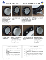
1 Nailer end caps are installed at
each end of the sleeve to prevent
deformation during the initial
concrete pour and hold sleeve
in exact location. Place one end
cap at each end of the sleeve.
2 Remaining end cap is inserted
into sleeve. Wide flange area
on cap provides good surface
against wall form, and resists
weight of concrete pour.
3 Workman checks sleeve
installation prior to erecting
outside form wall.
4 Keep end caps in place after wall
is poured and the form has been
removed. The end caps seal
sleeve against dirt and debris.
5 Just before pipe penetration,
caps are removed to reveal
clean inside surface of sleeve.
Order #
Ø pipe jacket D1 L
81012931 125 mm
(4.92 in)
208.5 mm
(8.21 in)
406.4 mm
(16.in)
81012932 160 mm
(6.30 in)
208.5 mm
(8.21 in)
406.4 mm
(16 in)
81012933 200 mm
(7.87 in)
258.8 mm
(10.19 in)
406.4 mm
(16 in)
Wall Sleeves come complete with end caps and corresponding Link Belts.
L
USA: 4500 East Progress Place, Springfield, MO 65803; www.wattsradiant.com
Canada: 5435 North Service Rd., Burlington, ONT. L7L 5H7; www.wattscanada.ca


