Page is loading ...

!
!
!
!
!
!
!
!
!
!
!
!
!
!
!
!
!
!
!
!
!
!
Wren
Inverted
Suspension
Forks
with Keyed Stanchions!
and TwinAir System
Owner´s Manual

Congratulations!
!
You have just purchased a Wren Inverted Suspension Fork. The culmination of years of design, testing and riding.
Please read this entire owner’s manual carefully before riding to learn about all the possibilities this fork
offers to you. Please make sure that you follow the safety and maintenance instructions strictly.
!
Modular Fork:
This fork is assembled and designed from a modular point of view. This means all parts can be exchanged for
new parts when needed. These parts can be ordered from your local dealer or service center. However, we prefer
that the service to internal parts be done by one of the certified service centers that we have appointed. If your
country has no service center available, the fork may be returned to our factory for service. If a fork is serviced by
anyone other than a certified service center, except for maintenance described in this manual, the consumer
warranty will void. Please refer to page 4 for complete fork description.
!
Fork Features
!
Hydraulic Damping with Adjustable Compression and Rebound (right leg):
The hydraulic oil damper is a sealed unit and designed to be repaired by a certified service center. You can
replace the damper by following the instructions in this manual. You can modify the fork’s ride and feel by
changing the presets as described in this manual.
!
Air Spring (left leg):
The air spring is fully serviceable and all parts are replaceable. We strongly recommend that this be done by a
certified service center. However, if you have good wrenching skills, you can do this yourself (check the
performance tuning section before doing this).
!
Dropouts and Quick Release:
This fork is made for QR15 hubs only and has a specific QR which is supplied with the fork and works with all
QR15 front hubs that fit your fork. Wheel installation on an inverted fork can be a bit tricky compared to regular
forks and requires attention. Before you insert the wheel, make sure both legs are at the same level and the
dropouts are facing forward, this makes QR assembly easier. The QR axle can only be inserted from the
BRAKE MOUNT (left) side of the fork. The lever must be on the BRAKE MOUNT side.
!
Warranty
The original manufacturer warrants this fork for a period of two years from the date of purchase to be free from
defects in materials or workmanship for the first owner only. During this warranty period we will replace or repair
any defective component of the fork. Paint, anodizing or seal damage caused by normal use (“wear and tear”) are
not covered by this warranty. We shall not be held liable for any damage caused by a crash, insufficient
maintenance or ignorance of the safety and maintenance instructions. We shall not be held liable for normal
maintenance, damage or failure due to abuse or misuse. A dated sales receipt must be presented to confirm fork
is still under warranty.
!
Important Safety and Maintenance Instructions
!
Warning:
It is extremely important that your Wren Inverted Fork be installed correctly by a dealer. Incorrectly installed forks
are dangerous and can result in loss of control of the bicycle and severe and/or fatal injuries. Follow the
instructions below to avoid this. If you do not follow these instructions, your warranty will be void.
!
Maintenance:
To maintain safety, long life and high performance of your Wren Inverted Fork, periodic maintenance is required. If
you frequently join competitions, ride in wet, muddy or other extreme conditions, a 50% reduction in
recommended maintenance intervals listed below is necessary.
!
1. After every ride clean and dry the exterior of your fork.
!
2. Minimum every 25 hours of riding you should check the smoothness of your fork. The stanchions need to run
smoothly up and down through the wipers. If they do not run smoothly, put 2-3 drops of a Teflon-based oil on
the stanchions and move them up and down through the compression stroke (this is easier when you release
some air pressure through the air valve).
!
3. Check if all dials and nuts are still tightened properly.
Page !2

4. Check the stanchion tubes for scratches and also inspect the lower seals for any wear or tear. If one of the
above mentioned parts appears damaged, do not ride and make repairs ASAP or send your fork to a certified
service center.
!
5. After 100 hours of riding, your fork should be fully serviced by a certified service center. You may contact your
dealer or Wren directly in order to find a certified service center.
!
General instructions:
!
1. This Wren fork is designed for off-road use. It is not designed for excessive riding like extreme jumps, etc. To
use it on-road, you will have to follow your country’s specific traffic regulations and laws and equip your bike
and your fork accordingly.
!
2. Do not ride your bike if you notice technical problems or material failures like bending, cracking or broken
parts. Immediately take your bike to a qualified dealer to prevent further damage. Failure to do this may result
in damage and severe and/or fatal injury.
!
3. Make sure the quick release lever is tightened and the hub axle is correctly fixed in the bore of the dropouts.
When the quick release is locked, the lever should point backwards in the horizontal position on the post
mount disc brake side of the fork. The QR axle can only be inserted from the BRAKE MOUNT (left) side of
the fork. The lever must be on the BRAKE MOUNT side.
!
4. Adjust the headset until there is no play or drag.
!
5. Install the brakes according to the manufacturer´s instructions and adjust brake pads properly. Use the fork
only with brakes that fit to the existing brake mounts and use up to a 160 mm rotor. For larger rotors up to a
maximum of 180 mm, use a proper post mount adapter for installation. Before riding the bicycle, ensure the
brakes are correctly installed and working properly.
!
6. Do not add threads to the thread-less steerer tube.
!
7. Do not replace the steerer tube by yourself as it needs to be pressed in under very high pressure.
!
8. Do not disassemble the damper cartridge yourself. High pressure inside the cartridge may cause injuries and
disassembly may lead to damage. Only an authorized service center should disassemble the oil cartridge. You
may replace the cartridge by following instructions in this manual.
!
9. The air side of the fork may be disassembled in order to modify the fork’s travel or travel and AC length in 10
mm increments. This is done by installing clips. This may be needed to make sure that your tire does not hit
the crown while the fork is fully compressed when using bigger volume tires. This must be checked properly
before each first ride with a different tire width or height. Generally, the 135 mm hub fork can fit up to a 4” tire
and the 150 mm hub fork can fit up to a 5” tire. Every rim tire combination can fit differently so you must check
your travel and clearance. See page 5 for how to modify travel.
!
10. Avoid directing water pressure at the stanchions and/or seals.
!
11. Be cautious when mounting the bicycle to a carrier. Carriers that hold the bike in trays with the wheels on are
preferred. Follow the instructions of the carrier manufacturer. Avoid mounting the bike by fixing it at the
dropouts (front wheel removed). The dropouts could be damaged.
!
12. If your bike is transported by air, release the air pressure from the air spring side of the fork before packing.
Deflating the air spring before transport avoids pressure damage and will guarantee proper function after
transport.
!
13. After a crash, have your bike and your fork inspected by a qualified dealer as internal damage may occur.
!
14. Always use genuine Wren parts. Use of different parts voids the warranty and could cause structural failure of
the fork resulting in loss of control of the bike with possible damage and/or injuries.
!
!
!
!
Page !3

"
Page !4
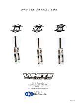
Complete Fork Description
Wren Inverted Suspension Fork
Right Dropout -
Damper Side
Steerer Tube
Red Air
Spring Cap
Blue Air Cap
Crown
Red Oil
Damper Cap
Collars &!
Wipers
Stanchion Tubes
Upper Legs
Red Rebound Dial
Left Dropout -
Air Side
Post Mount
Brake Mount
Blue
Compression/
Lockout Lever
Serial Number
Red Valve Cap - only
on TwinAir forks
Air Spring Insert
Bumper
(various sizes)
Black
Travel Clip
(if installed)
Air Spring Rod
Stanchion
Assembly Cap
Limiter Tube with
Large Steel Spring
Small Steel
Spring
White Spring
Platform
Air Piston
with Seals
Air Valve
Air Spring
Assembly Silver
Cap Nut
Air Valve
(for TwinAir if
equipped)
QR15 Quick Release Axle
Axle Nut
Axle
QR Lever
Note: QR must be inserted from
the brake side of the fork.
Upper Bushing

AIR Spring Travel and AC Length Modifications
!
Before your first ride you should check if you have enough tire to crown clearance. Depending on the
model, this fork comes standard with either 100 mm (505 mm AC), 110 mm (530 mm AC) or 150 mm (570
mm AC) of travel from the factory. If you are using narrow rims and big tires, you must check if you have
enough clearance between your crown and tire before you ride with this fork. If you do not have enough
clearance, the air spring needs to be modified with a clip(s) that will give you the proper clearance. Clips
are now supplied with every fork. If you have an older fork, you may contact us to purchase clips. The
clips reduce travel or travel and AC Length in 10 mm increments. As an example:
!
150 mm of travel - pre-set at factory
For 140 mm of travel - remove the pre-installed* 10 mm clip and insert 1 - 20 mm clip.
For 130 mm of travel - leave the 20 mm clip in place and add the 10 mm clip ABOVE the 20 mm clip. The 10 mm
clip must always be on top.
!
110 mm of travel - pre-set at the factory
For 100 mm of travel - remove the pre-installed* 10 mm clip and insert 1 - 20 mm clip.
For 90 mm of travel - leave the 20 mm clip in place and add the 10 mm clip ABOVE. The 10 mm clip must be on
top.
!
100 mm of travel - pre-set at the factory
For 90 mm of travel - remove the pre-installed* 10 mm clip and insert 1 - 20 mm clip.
For 80 mm of travel - leave the 20 mm clip in place and add the 10 mm clip ABOVE. The 10 mm clip must be on
top.
*
The pre-installed 10 mm clip does not reduce the advertised travel of the fork. It is installed to provide a safety
stop should the fork take a big hit. You should always ride with a clip in place on the TOP of the air spring. If you
take out the 10 mm clip and install a 20 mm clip, you will reduce the advertised travel by 10 mm as noted above.
If you decide to reduce the travel and AC length, leave the pre-installed 10 mm clip on the TOP of the air spring
and insert the correct clip INSIDE the air spring as noted on page 6.
!
Checking for Crown to Tire Clearance:
1. Install the front wheel on the fork being sure tire is properly inflated.
2. Release air from the air spring to make fork easier to compress.
3. Push down on the handlebars until the fork bottoms out and check for the amount of clearance between crown
and tire. A minimum of 5 mm is recommended, 10 mm is better if conditions might lead to snow or mud
buildup between the tire and crown.
!
Air Spring Travel Only Modification and Assembly:
1. Place your bike in a work stand and remove the front wheel.
2. Remove the blue air cap from the left leg and release all the air from the system. If your fork is a TwinAir, be
sure to empty both top and bottom air chambers.
3. Loosen and carefully remove the air spring assembly nut (large silver nut below the blue air cap) with a 26 mm
socket. This nut is low profile and care should be taken to firmly engage the socket. DO NOT remove the red
air spring assembly cap.
4. Unscrew the collars on the stanchions by hand. Now the air spring can be pulled out including the air side
stanchion from the bottom of the fork.
!
Warning: At this stage please absolutely make sure again that all the air has been released from the air
spring unit to avoid severe and/or fatal injuries.
!
5. Select the correct clip(s) as discussed above.
6. Insert the proper clip size into the air spring at the TOP directly below the upper assembly cap and onto the
flattened sides of the rod. For a 10 mm clip, snap onto the rod and slide up over the flattened surfaces under
the upper assembly cap. For the 20 mm clip, be sure the wide-mouth end is at the top, facing up. This end is
chamfered to fit over the flattened surfaces. Lineup with the flattened surfaces and snap onto the rod. If using
both stoppers, be sure the 10 mm is on TOP.
7. Wipe any old grease off the upper bushing and the sliding bushing on the stanchion and lightly re-grease with
a grease suitable for the temperature you will be riding in. If your fork is keyed, lightly grease the keys. For
general use we recommend Slick Honey.
8. Reverse steps 1 to 4 for reassembly. If your fork is keyed, be sure to lineup the keys properly. Be sure the
sliding bushing is completely pressed into the upper before tightening the collars. Be sure to torque the air
spring assembly cap to 10 Nm. Be sure the fork collars are hand tight. Be sure to check your air pressure and
sag.
!
Page !5

Air Spring Travel and AC Length Modification and Assembly:
!
You can reduce travel and the AC Length of the fork by placing the travel clips INSIDE the air spring.
!
1. Follow steps 1 through 4 above to remove the stanchion with the air spring from the fork. Be sure ALL air is
released from the air spring.
2. Looking at the top of the air spring, you will see a silver cap with 2 holes. This is the stanchion assembly cap.
Using a pair of bent nose pliers in the holes, unscrew the cap completely.
3. Grip the top of the air spring firmly and pull it out of the stanchion. This may take some effort.
4. Locate the Small Steel Spring at the bottom of the air spring. The clips will be installed on TOP of that spring
and below the white spring platform above that spring. The clips snap onto the rod same as above.
5. If only one clip is used, it must be the 20 mm clip because it is designed to rest on the spring. Remember that
the wide-mouth side of the 20 mm clip must face UP. The 10 mm clip should only be used with the 20 mm clip
and must be installed on TOP of the 20 mm clip. So, you can reduce your AC and Travel by 20 mm or 30 mm.
A 10 mm clip suitable for use on its own is in development.
6. Be sure the Large Steel Spring is well greased. All coils should be well greased. If riding in cold weather, be
sure to use a grease specified for use in the temperature you will be riding in.
7. Lightly grease the air piston seals making sure all gaps between the black O-rings and the piston are filled.
We recommend using Molykote 55 grease for the air piston seals. Insert the air spring back into the
stanchion. You may have to release air through the valve as you push the air spring back into the stanchion.
CAREFULLY thread the stanchion assembly cap back into the stanchion making sure not to cross-thread the
cap and securely tighten with the bent nose pliers.
8. Wipe any old grease off the upper bushing and the sliding bushing on the stanchion and lightly re-grease with
a grease suitable for the temperature you will be riding in. If your fork is keyed, lightly grease the keys.
9. Now reverse steps 1 to 4 from the travel modification section and install the stanchion into the fork. If your
fork is keyed, be sure to lineup the keys properly. Be sure the sliding bushing is completely pressed into the
upper before tightening the collars. Be sure to torque the air spring assembly cap to 10 Nm. Be sure the fork
collars are hand tight. Be sure to check your air pressure and sag.
!
Fork Setup/Performance Tuning
Please follow these instructions if you want to modify the ride or feel of this fork. For additional information, please
ask your dealer or contact Wren directly.
!
After installing the fork on your bike correctly, you must determine the correct fork setup for your weight and riding
style. First step is to inflate the fork because the fork is shipped with less air than you need to ride (air freight
requires forks at very low or no air pressure). Remember, the following is a guide. The final settings are
determined by paying attention to the feel of the fork and adjusting over your first few rides.
!
Air Spring - TwinAir
If your fork is equipped with an air valve on the bottom of the Air side (left) leg, you have a TwinAir fork. This fork
has air valves top and bottom under protective caps. Begin by filling both chambers with 30psi as a STARTING
point to set your sag (see below). Adjusting the pressure up or down in the top or bottom chamber affects slow
speed compression. This can help smooth out the small stuff. Once sag is set, increasing air in the top chamber
will give the fork a plusher feel, increasing air in the bottom chamber gives the fork a stiffer feel. The only way you
will know for sure how it affects your ride is to play with it on your first few rides. Maximum air pressure is
120psi. The TwinAir system is a single chamber divided in half by a floating piston similar to the air piston on the
air spring. Once sag is set, adding air to one side only will move the piston away increasing the volume of that
chamber. Because the piston floats, air pressure will still be close to equal in both chambers, but one chamber is
now larger. The change in volume between the chambers controls the feel of your ride.
!
Air Spring - Single Air
If you have a single air valve on top of the left leg, you have a single air fork. Remove the blue air valve cap and
use a suspension pump to pump up the fork to 30 psi as a starting point. Push down on the fork a few times to
determine if it feels about right for you. Adjust pressure if necessary. Maximum air pressure is 120psi. Now
check for the proper sag.
!
Fork Sag Setup:
Sag is the amount of travel that is used when a rider sits on the bike and the suspension compresses under the
rider’s weight. Sag, also known as negative travel, is needed to achieve a well-functioning fork. Sag on this fork
should be around 20% of the fork’s travel. This can be easily measured by first locating the rubber o-rings on the
stanchion tubes. Be sure no one is on the bike and the fork is uncompressed. Slide the o-rings up against the
wipers. Now carefully sit on the bike in your riding position with all your gear and let your weight slowly compress
the fork. Do not bounce the fork. Carefully dismount being sure not to compress the fork. Now measure the
distance between the o-rings and the wipers. If the distance for the 110 mm travel fork is around 22 mm, your
Page !6

starting sag setup is good. If the distance is less than 22 mm, reduce the air pressure in the air spring. If the
distance is more than 22 mm, increase the air pressure in the air spring. Remember, for a TwinAir fork add or
decrease pressure equally when setting your sag. You will always have a very small amount of pressure
difference between the top and bottom chambers even when equally filled. This setup is now your starting point.
Adjustments from here need to be done as you ride and feel out your new fork.
!
Rebound Knob:
The rebound speed of the hydraulic damper can be fine-tuned by turning the external red knob at the bottom of
the right leg. Turn the knob clockwise for slower rebound. Slower rebound means that the outward movement of
the fork after compression is slower (the damping is higher). Turn the knob counter-clockwise for faster rebound.
Faster rebound brings the fork back to its original position faster. For bumpy rides, we recommend a fast setting to
avoid over-damping. To start, try setting the rebound knob to the middle setting.
!
Do not turn the rebound knob past its limits. Squishy sounds in the sealed rebound stages are normal, it’s just the
oil flowing back into the compression stage of the cartridge. This means your fork works! If you choose a faster
rebound setting, the squishy noise will lessen and the fork will bounce back to its extended position faster, but the
damping will become less.
!
Lockout / Compression Adjustment Lever:
In addition to the rebound adjustment, the fork can be completely locked out from compression by the lockout
system. Just turn the blue lockout lever clockwise until its limit to lock out the fork (do not move past this limit). We
recommend this when climbing uphill or when no front suspension is needed. A very slight inward movement of
the fork may appear even when the lockout is activated. This is required to avoid damage to the cartridge and the
fork. To unlock the lockout function, turn the lockout lever counter-clockwise (do not move past the fully open
limit).
!
In between the two limits (fully open / locked) is the compression adjustment range.
The compression becomes firmer when the lever is turned clockwise toward the lockout and softer when turned
counter-clockwise toward the fully open position.
!
First Ride
It is advised to ride the fork on a flat surface at first in order to make any adjustments necessary to achieve the
ride you want. A new fork will have slight seal friction. Seals and stanchions need to break in and after a few hours
of riding the fork will move up and down smoother. If this changes the feeling you want, simply readjust your
settings. On your first off-road ride, it is advised to bring a suspension pump in order to be able to make additional
adjustments if needed.
!
Wren Suspension Fork Damper Replacement Instructions!
1. The damper is contained inside the right leg of the fork with the blue lockout lever on top. Lock the fork using
the blue lockout lever.!
2. For safety, release all air from the air spring (left leg). Remove the QR axle.!
3. Using a 2 mm allen wrench, remove the bolt from the center of the blue lockout lever on top of the fork.
There is a very small ball under the lever and under the ball is a very small spring. Carefully lift the lockout
lever off the fork watching that you do not lose the ball. The spring may stay in the detent, but you should
remove it as you will be turning the fork upside down next.!
4. Turn the fork upside down. At the bottom of the same leg, locate the red rebound knob. Turn the knob until
you can see a small hole on the side. Do not force the knob beyond its stops. Insert a 1.5 mm allen wrench
into the hole and unscrew the bolt until the knob slides off the shaft. It is not necessary to take the bolt
completely out.!
5. Using a 9 mm socket, remove the rebound fitting from the bottom of the stanchion. This fitting also contains
the adjustment shaft. Be sure not to lose the rubber O-ring and washer. The O-ring may stay in the bottom
of the stanchion, but be sure to carefully remove it.!
6. Turn the fork back upright and locate the 27 mm silver nut on top of the upper leg. This nut is very low profile
and care needs to be taken that the wrench or socket is firmly engaged. Loosen and completely unscrew the
nut. Remove the old damper from the upper leg.!
Page !7

7. At this point, if you want to re-lubricate the bushings and stanchion, unscrew the collar and pull the
stanchion out of the upper. Lubrication and reassembly is same as for the air side stanchion.!
8. Now you are ready to insert the new damper. First, you must slowly pull the lower rod of the damper out so
that it will reach the bottom of the stanchion when installed. If the damper is locked, you must unlock it by
using the blue lockout cap or a 5 mm wrench on the fitting on top of the damper and turning counter-
clockwise. Now slowly pull the rod out until it stops and re-lock the damper.!
9. Now insert the damper into the upper leg and slowly push down until the threads engage in the top of the
upper leg. You may have to pull the stanchion down to allow the insert to fit. Hand tighten the damper into
the upper. Now carefully tighten the 27 mm silver nut to 12.5 Nm with a torque wrench.!
10. Turn the fork back upside down and reassemble the rebound fitting from step 5. First, be sure the shaft of
the damper is centered and pushed against the hole on the bottom of the stanchion. You can carefully move
the shaft by inserting an allen wrench into the shaft and move it until it drops into the recess on the bottom of
the stanchion and is now centered. You may have to move the stanchion in or out slightly for the shaft to find
the recess. Now take the time to locate a small detent on the top side of the shaft on the rebound fitting
through the hole in the collar and be sure they are lined up and facing out away from the dropout. You must
line these up with the rebound knob allen bolt later. Screw the fitting into the hole on the bottom of the
stanchion making sure the O-ring and washer are in place. Tighten the 9 mm nut to 5 Nm with a torque
wrench.!
11. Now you must lineup the detent on the shaft, the hole in the collar and the allen bolt in the red rebound knob
so that the allen bolt tightens through the hole in the collar and into the detent on the shaft. Using a 1.5 mm
allen wrench tighten until the allen bolt makes firm contact with the shaft. The allen bolt should recess into
the hole 2 - 3 turns. If the allen bolt tightens before disappearing into the hole, you have not lined everything
up correctly. Do not over tighten as that will cause the rebound knob to be hard to move. The allen bolt has
loctite applied to it. Over time this could wear off and new loctite should be applied.!
12. Now turn the fork back upright and reassemble the blue lockout lever from step 3. Notice that there are 6
holes on top of the damper cap. Three have small 1.5 mm allen bolts visible and 3 are open. Loosen the 3
allen bolts just enough so you can rotate the cap counter-clockwise slightly. Now place the blue lockout cap
on the damper shaft and rotate clockwise at least 90° and continue turning until reaching the position you
want for lockout. We recommend the 6 o’clock position pointing back at the rider, but you can position where
you want it. Remove the lockout lever and snug the 1.5 mm allen bolts. This locks in your lockout lever
position. Lightly grease the very small spring and insert into one of the open holes closest to your lockout
lever position. Place the ball on top of the spring.!
13. Next, place the blue lockout lever on top of the damper in the lockout position you selected and push down
to be sure the lever makes full contact on the shaft. Reapply loctite to the allen bolt, if necessary, insert the
allen bolt and tighten snugly with a 2 mm allen wrench. Damper replacement is complete. Remember to refill
the air spring and reset your sag before riding. If your damper needs repair, we recommend replacement or
sending your damper to one of our authorized service centers."
"
Thank you for purchasing the Wren Inverted Suspension Fork. To see other fine Wren products, please visit
www.wrensports.com. Should you ever have any questions, comments or just need more information,
please contact us at:"
"
Wren Sports, LLC"
106 Camino del Sol"
Vallejo, CA 94591"
707-652-2737"
www.wrensports.com!
!
!
0516A
Page !8
/