Page is loading ...

2
IC0020: iCLASS
®
Module
Installation Supplement
To be used when IC0020 is added to an electric strike
HES, Inc.
Phoenix, AZ
800-626-7590
The iCLASS Module can be supported by the
electrical connection to the electric strike, or
by mounting it directly to the back of some
models of HES electric strikes using the #6-32
module mounting screws. Do not attempt to
support the iCLASS Module with the 18”
antenna cable.
Dielectric
Grease
www.hesinnovations.com
3
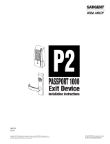
iCLASS Module
#6-32 Module Mounting Screws (for optional strike mount)
Reader/Antenna Body
#6-32 Reader/Antenna Screws
Reader/Antenna Mounting Plate
1
2
3
4
5
6
7
18” Cable (connecting reader/antenna and iCLASS module)
8
9
2 pin DPS & LBM Pigtail Connector
Data Connector (connects to iCLASS Module)
11
Dielectric Grease (apply to connections in humid applications)
10
4 pin 12V Strike Power Pigtail
4 pin 24V Strike Power Pigtail
8 pin Connector (iCLASS Module) Pigtail
12
Door Position Sensor (DPS)
13
DPS/LBM Adapter
-or-
4
5
7
10
6
8
9
1
3
Access Control System
Control Panel and Power Supply
(By others)
To Electric Strike power
11
12
To Access Control System
To Electric Strike LBM
13
Wiring Diagram
OR
8 Pin Connector (iCLASS Module) Pigtail
Red (+) Board Power
Black ( ) Board Power
Green Data 0
White Data 1
Yellow LED/Buzzer
Blue Not Used
Orange Not Used
Brown Not Used
-
11
4 Pin Connector (24V Strike Power)
Violet (24VDC +) Strike Power
Black ( - ) Strike Power
9
4 Pin Connector (12V Strike Power)
Red (12VDC +) Strike Power
Black (−) Strike Power
9
2 pin Connector (LBM Pigtail)
Tan Common
Pink Door Closed and Latch Engaged
8
Operating Voltage 12 to 24 VDC +/- 10%
Operating Current 125 mA Max @ 12VDC
Cable Detail
Distance to Host 500 ft Max
Recommended Type 18-22 AWG
(Dependent on distance) Stranded and shielded
Compliance FCC Part 15/IC Class B
Door Position Sensor (DPS)
Contact Rating 300ma @ 30VDC
Switch Type Form A (SPST) Reed
Card reader HID
13.56 MHz
Supported credential formats
All iCLASS
MIFARE 14443A Read Only
ISO 15693, 14443A, 14443B (MIFARE CSN ONLY)
MIFARE transmits Wiegand data based on card
serial number in 26, 32, 34, 37, 40, 56 bit formats
Interfaces with any Weigand-compatible access
control system

IC0020: iCLASS
®
Module
Installation Directions
3. Drill a 3/8” hole for the door position switch (DPS) as required.
Note that the DPS may be positioned as desired, within the
limits of its 10” cable. If necessary (e.g. wood frames), drill a
channel from the DPS to the electric strike to accommodate
the 10” cable. Next drill a matching 3/8” hole in the door and
install the press-fit magnet so it will make contact with the DPS.
Wire Gauge Diagram
12VDC
100’ or less
24 Gauge
2
Distance In ft, Round Trip
100’ to 200’
200’ to 300’
300’ to 400’
400’ to 500’
22 Gauge
22 Gauge
22 Gauge
20 Gauge
24VDC
24 Gauge
24 Gauge
24 Gauge
22 Gauge
22 Gauge
© 2011 HES, Inc.
3078006.003 rev A
Non-surface mount for
electric strike installation
Surface mount
electric strike installation
Connect Components and Wiring
5. Select the appropriate 4-pin strike power pigtail tha matches system
power. For 12V AC/DC or 16V AC, the pigtail marked “12 VDC” should
be used. For 24V AC/DC, the pigtail marked “24 VDC should be used.
6. Verify that the wires running from the control panel are of adequate
wire gauge (see Wire Gauge Diagram below). Connect the wire leads of
the three pigtails provided (items 8, 9, & 11) to the control panel wiring
based on the wiring diagram on page 1 and the appropriate termination
at the control panel.
7. Mount the door position switch (DPS) into the frame. Route the cable
back to the electric strike and connect it to the 2 pin connector of item
13, adapter cable. Connect the 3 pin connector from the strike to the 3
pin connector of item 13. Connect the remaining 2 pin connector of
item 13 to the 2 pin connector of the iCLASS. The LBM & DPS are wired
in series--a ‘closed’ electrical circuit depicts a closed door and extended
latchbolt into the integrated electric strike.
8. Secure the reader/antenna mounting plate to the frame using the #6
sheet metal screws provided. Connect the 18” cable to the reader/
antenna, snap the reader/antenna to the reader/antenna mounting
plate and pull the 18” cable through to the iCLASS Module.
9. Attach all the 8, 4 and 2 pin connectors to the equivalent pigtail
connectors routed from the control panel. Dielectric grease can be
applied to the pigtail electrical terminals if used in a humid
environment.
10. Slide the iCLASS module through either the access slot or the electric
strike cutout depicted in the illustrations to the left.
11. Install the electric strike unit in the frame as specified in the specific
strike installation instructions.
Testing and Operation
12. When power is supplied, the LED will turn red, while the beeper beeps
3 times. This sequence indicates the micro-controller is operating
properly.
13. Present a iCLASS ID card to the reader/antenna. The LED will turn
green, while the beeper beeps once. This indicates that the card was
read successfully. Simultaneously, the keeper will click open. This
indicates that communication between the control panel and the
electric strike is operational.
Reorient or relocate the receiving antenna.
Increase the separation between the equipment and receiver.
Connect the equipment into an outlet on a circuit different from that to which the receiver is connected.
Consult the dealer or an experienced radio/TV technician for help
Warning: Changes or modification to this device not expressly approved by HES
®
, Inc., could void the user’s authority to operate the equipment.
NOTE: This equipment has been tested and found to comply within the limits for a class [B] digital device, pursuant to Part 15 of the FCC Rules. These
limits are designed to provide reasonable protection against harmful interference in a residential installation. This equipment generates, uses, and can
radiate radio frequency energy and, if not installed and used in accordance with the instructions, may cause harmful interference to radio or television
reception, which can be determined by turning the equipment off and on. The user is encouraged to try to correct the interference by one or more of the
following measures:
This class [B] digital apparatus meets all requirements of the Canadian Interference Causing Equipment Regulations.
Operation is subject to the following two conditions: (1) this device may not cause harmful interference, and (2) this device must accept any interference
received, including interference that may cause undesired operation. Cet appareillage numérique de la classe [B] répond à toutes les exigences de
l’inerférencé canadienne causant des réglements d’équipement. L’opération est sujette aux deux conditions suivantes: (1) ce dispositif peut ne pas causer
l’interférence nocive, et (2) ce dispositif doit accepter n’importe quelle interférence reçue, y compris l’interférence quipeut causer ’opération peu désirée.
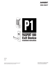
Prepare Frame and Strike
1. Prepare door jamb per the Installation Instructions provided
with the electric strike.
2. On the outside side of the frame drill a 3/4” diameter hole for
reader/antenna install per the image below. The reader/
antenna may be positioned as desired, within the limits of
the 18” cable connected to the iCLASS Module.
1-5/16” [33]
5/8” [16]
3/4” [19]
DPS: 3/8” [10]
Cut
between
holes to
make this
slot
See 9400,9500/9600
installation instructions
for these wire hole locations
/