
WIRELESS RSM FOR
PORTABLES SOLUTIONS
USER GUIDE
ACCESSORIES
PMMN4096 WIRELESS REMOTE SPEAKER MICROPHONE
PMLN6714 DUAL-UNIT CHARGER
PMLN6716 VEHICULAR CHARGER
PMNN4461 WIRELESS REMOTE SPEAKER MICROPHONE BATTERY

BackCover.fm Page 1 Wednesday, November 9, 2016 11:11 AM

FOREWORD
English
i
CHAPTER 1: FOREWORD
Important Safety Information
RF Energy Exposure and Product Safety Guide
for Portable Two-Way Radios
ATTENTION!
This radio is restricted to Occupational use only.
Before using the radio, read the RF Energy Exposure and Product
Safety Guide for Portable Two-Way Radios which contains important
operating instructions for safe usage and RF energy awareness and
control for Compliance with applicable standards and Regulations.
For a list of Motorola Solutions-approved antennas, batteries, and other
accessories, visit the following website:
http://www.motorolasolutions.com
Under Industry Canada regulations, this radio transmitter may only
operate using an antenna of a type and maximum (or lesser) gain
approved for the transmitter by Industry Canada. To reduce potential
radio interference to other users, the antenna type and its gain should
be so chosen that the equivalent isotropically radiated power (e.i.r.p.) is
not more than that necessary for successful communication.
Notice to Users (FCC and Industry Canada)
This device complies with Part 15 of the FCC rules and Industry
Canada's license-exempt RSS's per the following conditions:
• This device may not cause harmful interference.
• This device must accept any interference received, including
interference that may cause undesired operation.
• Changes or modifications made to this device, not expressly
approved by Motorola, could void the authority of the user to operate
this equipment.

FOREWORD
English
ii
Battery Information:
Battery is shipped with a nominal charge between 30% and 50%.
Battery should be stored between -10 °C (14 °F) and 30 °C (86 °F) to
minimize permanent capacity loss.
CAUTION: Storing your fully charged accessory in high-temperature
conditions may permanently reduce the life of the internal
battery.
Important Information:
• Hold the microphone in a vertical position with the microphone at
least one inch (2.5 centimeters) away from the nose or lips.
• Body Worn Operation. When microphone is worn on the body, always
use Motorola-approved clip for this product. Using approved body-
worn accessories is important because the use of non-Motorola-
approved accessories may result in exposure levels, which exceed
the FCC occupational/controlled environment RF exposure limits.
• Use only Motorola-approved supplied or replacement batteries. Use
of non-Motorola-approved batteries may exceed the applicable RF
exposure guidelines (iEEE, ICNIRP or FCC).
• DO NOT charge your accessory in temperatures below 0 °C (32 °F)
or above 45 °C (113 °F). DO NOT store your accessory in direct
sunlight or where expected temperatures can exceed this range such
as inside a parked car.
• Storing your fully charged accessory in high-temperature conditions
may permanently reduce the life of the internal battery.
• Battery life may temporarily shorten in low-temperature conditions.
Acoustic Safety
Exposure to loud noises from any source for extended periods of time
may temporarily or permanently affect your hearing. The louder the
radio's volume, the less time is required before your hearing could be
affected. Hearing damage from loud noise is sometimes undetectable at
first and can have a cumulative effect.
To protect your hearing:
• Use the lowest volume necessary to do your job.
• Turn up the volume only if you are in noisy surroundings.
• Turn down the volume before adding headset or earpiece.
• Limit the amount of time you use headsets or earpieces at high
volume.
• When using the radio without a headset or earpiece, do not place the
radio's speaker directly against your ear.
CHARGERS SAFETY INFORMATION
Important Safety Information
This document contains important safety and operating
instructions. Please read these instructions carefully and save
them for future reference.
Before using the battery charger, read all the instructions and cautionary
markings on (1) the Dual-Unit Charger / Vehicular Charger, (2) the
battery, and (3) on the Wireless Remote Speaker Microphone (WRSM).

FOREWORD
English
iii
WARNINGS
NOTE: The Dual-Unit Charger is not designed to accommodate the
alkaline battery tray.
OPERATIONAL SAFETY GUIDELINES
Dual-Unit Charger PMLN6714_
• This equipment is not suitable for outdoor use. Use only in dry
locations/conditions.
• Ensure the WRSM with attached battery or battery alone is dry before
inserting into the Dual-Unit Charger.
• Connect equipment only to an appropriately wired power supply of
the correct voltage (as specified on the product). Disconnect from line
voltage by removing main plug.
• The socket outlet to which this equipment is connected should be
close by and easily accessible.
• Maximum ambient temperature around the Dual-Unit Charger
equipment must not exceed 50 °C (122 °F).
• Output voltage from the power supply unit must not exceed the
ratings stated on the product label located on the power supply.
• Make sure the cord is located where it will not be stepped on, tripped
over, or subjected to water, damage, or stress.
!
W A R N I N G
!
2. Use of accessories not recommended by Motorola may result in
risk of fire, electric shock, or injury.
3. To reduce risk of damage to the electric plug and cord of the
DUC, pull by the plug rather than the cord when disconnecting
the charger.
4. To reduce risk of damage to the CLA and cord of the Vehicular
Charger, pull by the CLA rather than the cord when disconnecting
the charger.
5. An extension cord should not be used unless absolutely
necessary. Use of an improper extension cord could result in risk
of fire and electric shock. If an extension cord must be used,
make sure that the cord size is 18 AWG for lengths of up to
100 feet (30.48 m), and 16 AWG for lengths up to 150 feet
(45.72 m).
6. To reduce risk of fire, electric shock, or injury, DO NOT operate
the charger if it has been broken or damaged in any way. Take it
to a qualified Motorola service representative.
7. DO NOT disassemble the charger – it is not repairable and
replacement parts are not available. Disassembly of the charger
may result in risk of electric shock or fire.
8. To reduce risk of electric shock of the DUC, unplug the charger
from the AC outlet before attempting any maintenance or
cleaning.
9. To reduce risk of electric shock of the Vehicular Charger, unplug
the Vehicular Charger from the CLA power source before
attempting any maintenance or cleaning.
10. This is a class A product. In a domestic environment this product
may cause radio interference in which case the user may be
required to take adequate measures.
1. To reduce risk of injury, charge only the rechargeable
Motorola authorized batteries listed in Table 1.1. Other
batteries may explode, causing personal injury and
damage.
Table 1.1: Motorola Authorized Battery
Kit (Part) Number Platform/Description
PMNN4461_ Battery Standard Li-Ion 1750M1880T

FOREWORD
English
iv
Vehicular Charger PMLN6716_
• Equipment shall be used in vehicle and in dry condition. Keep in mind
that rain or snow can reach the equipment i.e. through an open
vehicle window.
• Ensure the WRSM with attached battery or battery alone is dry before
inserting into the Vehicular Charger.
• Connect equipment only to an appropriately vehicle’s cigar lighter
socket of the correct voltage (as specified on the product).
Disconnect from line voltage by removing the CLA.
• Maximum ambient temperature around the Vehicular Charger
equipment must not exceed 60 °C (140 °F).
• Output voltage from the vehicle’s cigar lighter socket unit must not
exceed the ratings stated on the product label located at the back of
the charger.
• Make sure the cord is located where it will not be stepped on, tripped
over, or subjected to water, damage, or stress.
RADIO COMPATIBILITY
The Wireless Remote Speaker Microphone (WRSM) is compatible with
the radios listed below:
Table 1.2: Radios Compatibility
Kit (Part) Number Platform/Description
North America
XPR7550, XPR7580, XPR7350,
XPR7380, XPR7550e, XPR7580e,
XPR7350e, and XPR7380e
Latin America
DGP8550e, DGP5550e, DGP8050e,
DGP5050e, and DGP8050e
European and Middle East
DP4801e, DP4601e, DP4401e, DP4801,
DP4601, DP4401, DP3441e, and
DP3661e
Asia Pacific
XiR P8668i, XiR P8628i, XiR P8608i, XiR
E8608i, and XiR E8608

FOREWORD
English
v
OPERATION MODE CONFIGURATION
By default, the WRSM is compatible with the radio ONLY. To work with
WAVE 5000 Mobile Client, choose WAVE 5000 on Operation Mode at
Accessory Programming Software (APS).
The APS tool allows you to select two modes of operation:
• Radio mode – configuring the WRSM to be used with your radio.
Refer to Table 1.2 for radios compatible to the WRSM.
• Wave5k mode – configuring the WRSM to be used with the Wave
5000 Mobile Client on a smartphone.

FOREWORD
English
vi
NOTES

WIRELESS RSM PMMN4096_
English
1
CHAPTER 2: WIRELESS RSM
PMMN4096_
PREPARING YOUR WRSM FOR USE
Assemble your WRSM by following these steps:
Assembling the Swivel Clip . . . . . . . . . . . . . . . . . . . . . . . . . . . . page 2
Attaching the Battery . . . . . . . . . . . . . . . . . . . . . . . . . . . . . . . . . page 2
Detaching the Battery. . . . . . . . . . . . . . . . . . . . . . . . . . . . . . . . . page 3
Charging the Battery . . . . . . . . . . . . . . . . . . . . . . . . . . . . . . . . . page 3
Language Selection . . . . . . . . . . . . . . . . . . . . . . . . . . . . . . . . . . page 4
Recommended Wearing Positions. . . . . . . . . . . . . . . . . . . . . . . page 5

WIRELESS RSM PMMN4096_
English
2
Assembling the Swivel Clip
Insert the swivel clip through the battery slot. Rotate the clip to the right
position as indicated in Figure 2.1 below.
Figure 2.1: Assembling the swivel clip
Attaching the Battery
With the WRSM turned off, align the battery to back chassis and fully
slot in until the battery latch is engaged.
Figure 2.2: Attaching the battery into the WRSM
2
1
1
2

WIRELESS RSM PMMN4096_
English
3
Detaching the Battery
To detach the battery, lift up the battery latch and pull the battery
backward until the battery is fully disengaged from the back chassis.
Figure 2.3: Removing the battery from the WRSM
Charging the Battery
Figure 2.4: Charging position of the WRSM with battery attached
1
2
LED STATUS INDICATORS
R
eady
>90
%
C
A
U
TIO
N
C
ha
r
g
in
g
Stand
by
RISK OF FIRE. REFER TO MANUAL FOR BATTERY TYPE
U
n
ab
le to C
h
arge

WIRELESS RSM PMMN4096_
English
4
The Motorola-approved battery shipped with your WRSM is uncharged.
Prior to using a new battery, fully charge the new battery to ensure
optimum capacity and performance.
NOTE: When charging a battery attached to a WRSM, turn the
WRSM OFF to ensure a full charge.
Battery Charger
To charge the battery, place the battery, with or without the WRSM, in a
Motorola-approved charger. When initially inserting the battery into the
charger, the charger’s LED will turn red. DO NOT use WRSM until the
charger’s LED turn Green,
The charger’s LED indicates the charging progress; see Chapter 3 and
Chapter 5 or the label printed on the charger.
Align the slot of the battery with the charger’s rail and slot in. Refer to
Figure 2.4.
Language Selection
Follow the procedure below if you want to reset to your desired
language. Ensure that the WRSM is powered OFF before starting this
procedure.
Procedure:
1 Press and hold the PTT button before powering ON the WRSM.
DO NOT release the PTT button.
2 Continue holding the PTT Button until the prompt to select
language.
3 Select your desired language by pressing the PTT button. Refer to
Table 2.1 below for the Language Selection Indicators.
To avoid a possible explosion:
• DO NOT replace the battery in any area labeled
“hazardous atmosphere”.
• DO NOT discard batteries in a fire.
!
W A R N I N G
!
Table 2.1: Language Selection Indicators
State Power Indication LED Voice Prompt
Language Selection LED illuminated
“For English press PTT
now” (Menu selection
prompts)

WIRELESS RSM PMMN4096_
English
5
Figure 2.5: Language Selection
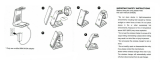
Recommended Wearing Positions
For optimum performance, wear the WRSM as highlighted in Figure 2.6
below.
Figure 2.6: Recommended wearing positions
NOTE: When the WRSM is worn on the body, always use Motorola-
approved clip. Using approved body-worn accessories is
important because the use of non-Motorola-approved
accessories may result in exposure levels, which exceed the
FCC occupational/controlled environment RF exposure limits.
1
2
Push-to-Talk
(PTT) Button
Power Button /
Multi Function
Button (MFB)

WIRELESS RSM PMMN4096_
English
6
IDENTIFYING WRSM INDICATORS AND
CONTROLS
Take a moment to review the following:
Overview of the WRSM . . . . . . . . . . . . . . . . . . . . . . . . . . . . . . . page 6
Power Indicators and Battery Alerts . . . . . . . . . . . . . . . . . . . . . page 7
Audio Indicators. . . . . . . . . . . . . . . . . . . . . . . . . . . . . . . . . . . . . page 7
Overview of the WRSM
Figure 2.7: Wireless Remote Speaker Microphone Overview
Audio Indicator
1
2
Programmable
Button
(Orange Button)
Audio Jack
3
Microphone
4
Speaker
5
Tasklight
6
Tasklight
Button
7
Push-to-Talk
(PTT) Button
8
Power
Indicator
9
10
Power Button /
MFB
11
Volume Toggle

WIRELESS RSM PMMN4096_
English
7
Power Indicators and Battery Alerts
The WRSM is battery powered. It is very important to pay attention to
the low battery warning described in Table 2.2 to avoid improper
functioning of the WRSM.
Audio Indicators
Table 2.2: Power Indicators and Battery Alerts
State
Power Indication
LED
Tone Indication
Remaining
Battery Life
Normal
Battery
Green
No tone
11 hours
(full charged) –
30 minutes
Low
Battery
Amber
Low Battery tone
every 2 minutes
Less than
30 minutes
Critical
Battery
Red
Low Battery tone
every 30 seconds
Less than
10 minutes
Table 2.3: Audio Indicators
State Audio Indication LED
Audio Not Available,
Device Not Paired
Blue Blink
Audio Not Available,
Device Not Paired and Muted
Red Blink
Audio Available,
Good Signal
Blue Heartbeat
Audio Available,
Poor Signal / Edge of Range
Amber Heartbeat
Audio Available,
Muted
Red Heartbeat
Audio Not Available,
Disconnected / Reconnecting
Blue Solid

WIRELESS RSM PMMN4096_
English
8
GENERAL WRSM OPERATION
Once you understand how your WRSM is configured, you are ready to
use your WRSM. Use this navigation guide to familiarize yourself with
the basic features:
Powering ON/OFF the WRSM . . . . . . . . . . . . . . . . . . . . . . . . . . page 9
Volume Control. . . . . . . . . . . . . . . . . . . . . . . . . . . . . . . . . . . . . . page 9
Pairing Your WRSM . . . . . . . . . . . . . . . . . . . . . . . . . . . . . . . . . page 10
Subsequent Connection. . . . . . . . . . . . . . . . . . . . . . . . . . . . . . page 10
Poor Signal / Out Of Range Warning Indication. . . . . . . . . . . . page 11
Programmable Button (Orange Button) . . . . . . . . . . . . . . . . . . page 11
Tasklight Button . . . . . . . . . . . . . . . . . . . . . . . . . . . . . . . . . . . . page 12
Dark Mode . . . . . . . . . . . . . . . . . . . . . . . . . . . . . . . . . . . . . . . . page 12
Secondary Receiver Audio Accessory . . . . . . . . . . . . . . . . . . . page 13
Failure Detected Indication and Handling . . . . . . . . . . . . . . . . page 13
Troubleshooting . . . . . . . . . . . . . . . . . . . . . . . . . . . . . . . . . . . . page 13
Firmware Upgrade . . . . . . . . . . . . . . . . . . . . . . . . . . . . . . . . . . page 14
Audio Not Available,
Disconnected / Reconnecting
and Muted
Red Solid
Table 2.3: Audio Indicators (Continued)
State Audio Indication LED

WIRELESS RSM PMMN4096_
English
9
Powering ON/OFF the WRSM
To power ON the WRSM, press and hold the Power Button until you
hear “Motorola Solutions” prompt. To power OFF, press the Power
Button until the WRSM turns off.
Figure 2.8: Powering on your WRSM
Volume Control
To increase the volume, push volume lever towards the . To decrease
the volume, push lever towards the .
To mute, hold lever to the for 2 seconds. To unmute, push lever to
the or press the PTT button. Volume returns to the previous level.
Figure 2.9: Volume Control
The color of the Audio Indicator LED changes according to Table 2.3 on
page 7.
Table 2.4: Power ON/OFF LED and Tone Indicators
Power Power Indication LED Tone Indication Voice Prompt
ON LED blinks 3 times
“Motorola
Solutions”
“Motorola
Solutions,
Power On”
OFF
LED blinks 3 times then
OFF
Power Off tone “Power Off”
Power
Button
Power Indicator
Volume
Toggle
Audio Indicator

WIRELESS RSM PMMN4096_
English
10
Pairing Your WRSM
Procedure:
1 Verify that both the host and the WRSM are powered ON (First time
only: Once the WRSM is powered ON, if not previously selected,
the WRSM will instruct the user to select language or tone, and then
it goes into Pairing Mode automatically.).
2 Both the WRSM and wireless host must be within pairing range
(recommended pairing range is within 1 meter).
3 Once the devices are paired successfully, a “Pairing Successful”
tone or “Connecting” voice prompt is played on the WRSM.
4 Press the MFB button to start the connection process when you
hear the “Ring” tone indicating Host is requesting for connection.
5 Wireless Link Connected with Host indication is provided upon
successful link establishment (refer to Table 2.5 on page 10).
6 Your WRSM is now ready to be used.
Subsequent Connection
Same Host:
If the Bluetooth link is lost, connection will be automatically
reestablished when the host and device come within 10 meter range
(line-of-sight).
New Host:
1 Put the wireless device in Pairing Mode by powering ON while
pressing the PTT button simultaneously.
2 Follow steps from Pairing Your WRSM.
Table 2.5: Wireless Link and Pairing Indicators
State Indication LED
Tone
Indication
Voice Prompt
Entered Pairing
Mode
Blue LED blinking — “Cleared”
Not Paired Blue LED blinking
Pairing Ready
tone
“Searching for
Host”
Paired
Successfully
Blue LED Solid
for 2 seconds
Pairing
Successful tone
“Connecting”
Wireless Link
Connected with
Host
Blue LED
Heartbeat:
Long OFF and
Short ON
Connected tone
“Headset
Connected”

WIRELESS RSM PMMN4096_
English
11
Poor Signal / Out Of Range Warning
Indication
You will be prompted with the Poor Signal / Ouf Of Range Warning
Indication if the WRSM is about to lose the wireless link at Bluetooth
fringe area.
This warning indication will turn off if the user moves closer or if the
signal quality improves.
Refer to Table 2.6below for the Poor Signal / Out Of Range Indication:
Push-to-Talk (PTT) Button
Press and hold down the PTT button to talk. Release the PTT button to
listen. The microphone is activated when the PTT button is pressed.
Figure 2.10: Pressing Push-to-Talk Button
Programmable Button (Orange Button)
This Programmable Button is mapped to the Accessory Orange Button
for Portable Radios. Pressing the Programmable Button on the WRSM
will trigger the event set in Accessory Orange Button. The Accessory
Orange Button is programmable through radio’s Customer
Programming Software (CPS). Your radio’s User Guide contains a full
description of the programmable functions that are available through
this button.
Wireless Link
Disconnected
from Host
Blue LED Solid
ON
Disconnected
tone every
2 minutes
for 10 minutes
“Headset
Disconnected”
Table 2.6: Poor Signal / Out Of Range Warning Indicator
State Audio Indication LED Tone Indication
Poor Signal /
Ouf Of Range
Amber LED illuminated for
2 seconds
“Bad Bonk” Tone
Table 2.5: Wireless Link and Pairing Indicators (Continued)
State Indication LED
Tone
Indication
Voice Prompt

WIRELESS RSM PMMN4096_
English
12
Tasklight Button
Press the Tasklight Button for 1 second to switch ON/OFF the tasklight.
During low/critical battery, the Tasklight blinks for 30 seconds and will be
auto switched OFF.
NOTE: The Tasklight is disabled when WRSM is in Dark Mode.
Dark Mode
Dark Mode allows you to turn OFF the LEDs on the WRSM.
IMPORTANT: When the WRSM is in Dark Mode and muted state, all
indications will be turned OFF.
To activate the Dark Mode feature, follow the steps below:
Procedure:
1 Press and hold the Tasklight Button until Dark Mode is ON. The
Tasklight will blink for 1 second upon entering/exiting Dark Mode.
2 Refer to Table 2.7 below for the Dark Mode Indicators.
NOTE: To disable the Dark Mode feature, press the Tasklight Button
for 3 seconds.
NOTE: All three LEDs (Power Indicator, Audio Indicator & Tasklight)
blink for 1 second and off at the same time when turning ON/
OFF the Dark Mode.
Table 2.7: Dark Mode Indicators
Indication
Power Indication, Audio
Indication and Tasklight
LED
Tone
Indication
Voice Prompt
Dark Mode
ON
LED illuminated for 1
second then OFF
“Dark Mode”
tone
“Lights OFF,
Press and
hold Tasklight
Button to
switch lights
ON”
Dark Mode
OFF
LED illuminated for 1
second
“Dark Mode ”
tone
“Lights ON”
Page is loading ...
Page is loading ...
Page is loading ...
Page is loading ...
Page is loading ...
Page is loading ...
Page is loading ...
Page is loading ...
Page is loading ...
Page is loading ...
Page is loading ...
Page is loading ...
Page is loading ...
Page is loading ...
Page is loading ...
Page is loading ...
Page is loading ...
Page is loading ...
Page is loading ...
Page is loading ...
Page is loading ...
Page is loading ...
Page is loading ...
Page is loading ...
Page is loading ...
Page is loading ...
Page is loading ...
Page is loading ...
Page is loading ...
Page is loading ...
-
 1
1
-
 2
2
-
 3
3
-
 4
4
-
 5
5
-
 6
6
-
 7
7
-
 8
8
-
 9
9
-
 10
10
-
 11
11
-
 12
12
-
 13
13
-
 14
14
-
 15
15
-
 16
16
-
 17
17
-
 18
18
-
 19
19
-
 20
20
-
 21
21
-
 22
22
-
 23
23
-
 24
24
-
 25
25
-
 26
26
-
 27
27
-
 28
28
-
 29
29
-
 30
30
-
 31
31
-
 32
32
-
 33
33
-
 34
34
-
 35
35
-
 36
36
-
 37
37
-
 38
38
-
 39
39
-
 40
40
-
 41
41
-
 42
42
-
 43
43
-
 44
44
-
 45
45
-
 46
46
-
 47
47
-
 48
48
-
 49
49
-
 50
50


Motorola PMLN6716 User manual
- Type
- User manual
Ask a question and I''ll find the answer in the document
Finding information in a document is now easier with AI
Related papers
-
Motorola PMMN4095 series User manual
-
-
-
-
-
-
-
-
-
Other documents
-
 Body-Solid PUB30 Owner's manual
-
 miromtec GS-551 User guide
-
PowerTech MB-3667 User manual
-
DigiPower TC-2000 User manual
-
 AccuPoint tph700 User manual
-
Pulsar APS 5 User manual
-
Pulsar APS 5T Battery Packs and Charger User manual
-
TOA BC-900 CE/CE-GB/UL User manual
-
 Motorola Solutions PMLN4455 User guide
-


