Ambient Weather WS-1075 User manual
- Category
- Weather stations
- Type
- User manual

Version 1.2 ©Copyright 2016, Ambient LLC. All Rights Reserved. Page 1
Ambient Weather WS-1075 Home Weather Station User Manual
Table of Contents
1. Introduction ...................................................................................................................................................... 2
2. Product Features ............................................................................................................................................... 3
3. Warnings and Cautions ..................................................................................................................................... 4
4. Pre-Installation Checkout and Site Survey ....................................................................................................... 4
4.1 Pre Installation Checkout ......................................................................................................................... 4
4.2 Site Survey ............................................................................................................................................... 5
5 Getting Started .................................................................................................................................................. 5
5.1 Parts List .................................................................................................................................................. 5
5.2 Recommend Tools ....................................................................................................................................... 6
6 Sensor Assembly Set Up .................................................................................................................................. 6
6.1 Power the Thermo-Hygrometer Transmitter ............................................................................................ 6
6.2 Connect and Mount the Sensor Array (Pole Mount) ................................................................................ 7
6.3 Alternate Mounting to a Horizontal Surface ............................................................................................ 8
6.4 Display Console ....................................................................................................................................... 9
6.4.1 Display Console Layout ...................................................................................................................... 9
6.4.2 Initial Display Console Set Up ........................................................................................................... 11
6.4.3 Radio Controlled Clock (RCC) .......................................................................................................... 11
6.4.4 Sensor Operation Verification ............................................................................................................ 12
7 Weather Station Installation ............................................................................................................................ 12
7.1 Pre Installation Checkout ....................................................................................................................... 12
7.2 Site Survey ............................................................................................................................................. 12
7.3 Best Practices for Wireless Communication .......................................................................................... 13
7.4 Final Installation of Sensor Array .......................................................................................................... 13
8 Console Operation .......................................................................................................................................... 14
8.1 Set (Program) Mode............................................................................................................................... 14
8.1.1 Set Mode Reference Guide ................................................................................................................ 14
8.1.2 Set Mode Operation ........................................................................................................................... 14
8.2 Quick Set Mode ..................................................................................................................................... 17
8.2.1 Quick Set Mode Reference Guide ..................................................................................................... 17
8.2.2 Quick Set Mode Operation ................................................................................................................ 17
8.3 History Mode ......................................................................................................................................... 18
8.4 Alarm Mode ........................................................................................................................................... 18
8.4.1 High Alarm Mode .............................................................................................................................. 18
8.4.2 Low Alarm Mode ............................................................................................................................... 20
8.4.3 Cancelling an Alarm .......................................................................................................................... 21
8.4.4 Outdoor Temperature/ Wind Chill / Dew Point Alarm ...................................................................... 21

Version 1.2 ©Copyright 2016, Ambient LLC. All Rights Reserved. Page 2
8.5 Min/Max Mode ...................................................................................................................................... 21
8.5.1 Maximum Mode ................................................................................................................................ 21
8.5.2 Minimum Mode ................................................................................................................................. 22
8.6 Other Console Features .......................................................................................................................... 23
8.6.1 Weather Forecasting .......................................................................................................................... 23
8.6.2 Weather Icons .................................................................................................................................... 23
8.6.3 Weather tendency indicator ............................................................................................................... 23
8.6.4 Storm threshold indicator .................................................................................................................. 24
8.6.5 Pressure threshold setting .................................................................................................................. 24
8.6.6 Pressure Graph ................................................................................................................................... 24
9 Maintenance ................................................................................................................................................... 25
9.1 Cleaning the Rain Gauge ....................................................................................................................... 25
9.2 Thermo-Hygrometer Connectors ........................................................................................................... 25
9.3 Battery Contacts ..................................................................................................................................... 26
10 Glossary of Terms ...................................................................................................................................... 26
11 Specifications ............................................................................................................................................. 27
11.1 Wireless Specifications .......................................................................................................................... 27
11.2 Measurement Specifications .................................................................................................................. 27
11.3 Power Consumption ............................................................................................................................... 27
12 Troubleshooting Guide............................................................................................................................... 27
13 Accessories ................................................................................................................................................ 29
14 Liability Disclaimer ................................................................................................................................... 29
15 FCC Statement ........................................................................................................................................... 30
16 Warranty Information ................................................................................................................................. 30
1. Introduction
Thank you for your purchase of the Ambient Weather WS-1075 wireless weather station. The following user
guide provides step by step instructions for installation, operation and troubleshooting. To download the latest
manual and additional troubleshooting tips, please visit:
http://ambientweather.wikispaces.com/ws1075

Version 1.2 ©Copyright 2016, Ambient LLC. All Rights Reserved. Page 3
2. Product Features
Figure 1
Figure 2

Version 1.2 ©Copyright 2016, Ambient LLC. All Rights Reserved. Page 4
Indoor and outdoor temperature in degrees Fahrenheit or Celsius (user selectable)
Indoor and outdoor relative humidity
Barometric pressure reading in inHg or hPa, absolute or relative (user selectable)
Detailed display of rainfall data in 1 hour, 24 hours, one week, one month and total since last reset (user
selectable in mm or inch)
Wind speed in mph, km/h, m/s, knots or Beaufort (user selectable)
Wind chill temperature
Dew point temperature
Weather forecast display (sunny, cloudy, rainy)
Weather forecast tendency arrow
Storm warning alarm
Programmable alarms
Minimum and maximum values with time and date stamp
LED back light (temporary)
WWVB radio controlled time and date with manual setting option
12 or 24 hour time display
Perpetual calendar
Time zone setting
Daylight savings time setting with manual override
Wall hanging or free standing
Synchronized instant reception (updates once per 48 seconds)
3. Warnings and Cautions
Warning: Any metal object may attract a lightning strike, including your weather station mounting pole.
Never install the weather station in a storm.
Warning: Installing your weather station in a high location may result in injury or death. Perform as much
of the initial check out and operation on the ground and inside a building or home. Only install the weather
station on a clear, dry day.
4. Pre-Installation Checkout and Site Survey
4.1 Pre Installation Checkout
Before installing your weather station in the permanent location, we recommend operating the weather station for
one week in a temporary location with easy access. This will allow you to check out all of the functions, insure
proper operation, and familiarize you with the weather station and calibration procedures. This will also allow
you to test the wireless range of the weather station.

Version 1.2 ©Copyright 2016, Ambient LLC. All Rights Reserved. Page 5
4.2 Site Survey
Perform a site survey before installing the weather station. Consider the following:
1. You must clean the rain gauge every few months and change the rechargeable batteries every 1-2 years.
Provide easy access to the weather station.
2. Avoid radiant heat transfer from buildings and structures. In general, install the sensor array at least 5’
from any building, structure, ground, or roof top.
3. Avoid wind and rain obstructions. The rule of thumb is to install the sensor array at least four times the
distance of the height of the tallest obstruction. For example, if the building is 20’ tall, and the mounting
pole is 6’ tall, install 4 x (20 – 6)’ = 56’ away.
4. Wireless Range. The radio communication between receiver and transmitter in an open field can reach a
distance of up to 300 feet, providing there are no interfering obstacles such as buildings, trees, vehicles,
high voltage lines. Wireless signals will not penetrate metal buildings. Under most conditions, the
maximum wireless range is 100’.
5. Radio interference such as PCs, radios or TV sets can, in the worst case, entirely cut off radio
communication. Please take this into consideration when choosing console or mounting locations. Make
sure your display console is at least five feet away from any electronic device to avoid interference.
6. Visit Ambient Weather Mounting Solutions for assistance and ideas for mounting your weather station:
http://www.ambientweather.com/amwemoso.html
5 Getting Started
The WS-1075 weather station consists of a display console (receiver), a thermo-hygrometer transmitter unit, a
wind speed sensor, a rain gauge, and mounting hardware.
5.1 Parts List
QTY
Item
1
Display Console
1
Thermo-hygrometer transmitter (measures temperature and humidity)
1
Thermo-hygrometer transmitter mounting bracket
1
Thermo-hygrometer transmitter rain shield
1
Wind speed sensor
1
Wind cups
1
Rain gauge
1
Rain gauge mounting bracket
1
10mm set screw for rain gauge mounting
4
15mm set screws for mounting rain gauge and transmitter to horizontal surface
(optional)
1
19.5mm bolt and nut for transmitter (shorter bolt)
1
30mm bolt and nut for wind gauge (longer bolt)
2
40mm Pole mounting U-bolts for outdoor transmitter and wind gauge (larger)

Version 1.2 ©Copyright 2016, Ambient LLC. All Rights Reserved. Page 6
QTY
Item
2
38mm Pole mounting U-bolts for rain gauge (smaller)
8
8mm U-Bolt nuts for rain gauge and wind speed pole mounting
5.2 Recommend Tools
Precision screwdriver
8 mm wrench (for U-Bolt nuts)
6 Sensor Assembly Set Up
6.1 Power the Thermo-Hygrometer Transmitter
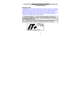
1. The thermo-hygrometer-transmitter (THT) comes pre-packaged inside the rain shield. Pull the
transmitter from the shield to expose the LED indicator, sensor sockets and battery compartment, as
shown in Figure 3.
Figure 3
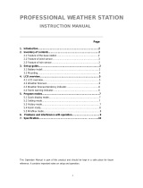
2. Remove the battery cover of the transmitter, and insert 2 x AA batteries into the battery compartment,
observing the polarity, as shown in Figure 4. Confirm the red LED above the battery compartment turns
on for four seconds, then off. The LED will flash every 48 seconds thereafter, signifying wireless
transmission. Close the battery door.

Version 1.2 ©Copyright 2016, Ambient LLC. All Rights Reserved. Page 7
Note: Refer to Section 9.2 for pre-treating the connectors and sockets.
Figure 4
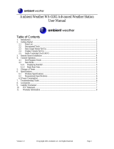
6.2 Connect and Mount the Sensor Array (Pole Mount)
Please reference Figure 5.
1. Attach the wind cups to the wind speed shaft. Press firmly, and the cups will snap into place. No set
screw is required.
2. Connect the wind cup shaft to the rain shield.
3. Secure the wind cup shaft to the rain shield with the 30mm bolt and nut.
4. Connect the wind sensor connector to the WIND sensor socket.
5. Connect the rain sensor connecter to the RAIN sensor socket.
6. Push the transmitter into the rain shield until snug.
7. Attach the transmitter to the transmitter mounting bracket.
8. Secure the transmitter to the transmitter mounting bracket with the 19.5mm bolt and nut.
9. Attach the rain gauge to the rain gauge mounting bracket and secure with the 10mm set screw.
10. Attach the rain gauge mounting bracket to the mounting pole (not included) using two U-bolts and nuts.
The rain gauge U-Bolts are slightly larger (40mm) than the thermo-hygrometer transmitter and wind
gauge U-Bolts (38mm). Tighten the U-Bolts around the pole using the nuts with an 8mm wrench. Use
the bubble level on the rain gauge to make sure it is completely level.
11. Attach the thermo-hygrometer transmitter and wind gauge mounting bracket to the mounting pole (not
included) using two U-bolts and nuts. Tighten the U-Bolts around the pole using the nuts with an 8mm
wrench.
Note: Mount the rain gauge below the wind transmitter and wind gauge so that water does not discharge
and drop water on the connectors.


Version 1.2 ©Copyright 2016, Ambient LLC. All Rights Reserved. Page 9
Figure 6
6.4 Display Console
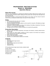
6.4.1 Display Console Layout
The display console layout is shown in Figure 7. Note that the alarm icons are only present when an alarm has
been set, the low battery icon is only present when there is a low battery, and the SENSOR: will only be on
during the initial search mode, and will flash once every 48 seconds thereafter.

Version 1.2 ©Copyright 2016, Ambient LLC. All Rights Reserved. Page 10
Figure 7
1. Time
2. Alarm on indicator
3. Day of week/ time zone
4. Date
5. Indoor temperature display
6. Indoor humidity display
7. Indoor temperature and humidity low alarm and
high alarm
8. Temperature display unit
9. General indoor alarm icon
10. MIN/MAX information
11. Wind chill and dew point temperature display
12. Outdoor temperature and humidity display
13. Outdoor temperature and humidity low alarm and
high alarm
14. Temperature display unit
15. General outdoor alarm icon
16. Weather forecast icon
17. Weather tendency indicator
18. Pressure unit (relative or absolute)
19. Pressure with 24 hour history graph
20. Pressure low alarm and high alarm
21. Pressure display unit (inHg or hPa)
22. Pressure alarm on indicator
23. Wind speed display unit (m/s, km/h, knots, chill
mph, bft)
24. Wind speed high alarm
25. Wind alarm on indicator
26. Rainfall display unit (mm/in)
27. Rainfall 1h, 24h,week, month or total hour display
28. Rainfall alarm on indicator
29. Low Battery indicator

Version 1.1 ©Copyright 2012, Ambient LLC. All Rights Reserved. Page 11
6.4.2 Initial Display Console Set Up
1. Place the sensor array 5 to 10 feet from the display console. It is best to perform this
operation prior to installing the sensor array.
2. Make sure the sensor array is already powered up and the transmitter light is flashing once
every 48 seconds.
3. Insert 3 x AA batteries into the battery compartment on the back of the display. After
inserting the batteries into the console, all of the LCD segments will light up for a few
seconds to verify all segments are operating properly.
4. The console will instantly display indoor temperature, humidity, barometer, tendency, date
and time. The wind speed, rain, and outdoor temperature and humidity will update on the
display within a few minutes. DO NOT TOUCH ANY BUTTONS until the outside
transmitter report in, otherwise the outdoor sensor search mode will be terminated. The sensor
search icon will be present:
5. When the outdoor transmitter data has been received, the console will attempt to receive the
Radio Controlled Clock (RCC) signal.
If the outdoor sensors do not update, please reference the troubleshooting guide in Section 12.
Figure 8
6.4.3 Radio Controlled Clock (RCC)
After the sensor array is received by the console, the sensor will transmit weather data for 30 seconds,
and then the sensor will begin radio controlled clock (RCC) reception. During the RCC time reception

Version 1.1 ©Copyright 2012, Ambient LLC. All Rights Reserved. Page 12
period (maximum 10 minutes), no weather data will be transmitted to avoid interference. The sensor
search icon will remain on.
If the signal reception is not successful within 1 minute, the signal search will be cancelled and will
automatically resume every two hours until the signal is successfully captured. The regular sensor
array link will resume once RCC reception routine is finished. In some locations, RCC reception may
take a couple of days to receive the signal.
The RCC reception routine can be cancelled at any time by pressing any button. The sensor search
icon will turn off, and the console will automatically switch to the normal mode, from which all
further settings can be performed.
Once the RCC has been received and the clock has been set, the RCC icon will appear in the date
and time field.
Note: The RCC is a shortwave signal originating near Fort Collins, Colorado, and travels thousands of
miles by bouncing off the ionosphere. The signal is better at night due to solar interference during the
daytime. The farther you are from Colorado, the weaker the signal. Urban environments can also
affect the signal.
6.4.4 Sensor Operation Verification
The following steps verify proper operation of the sensors prior to installing the sensor array outside.
1. Verify proper operation of the rain gauge. Tip the sensor array back and forth several times.
You should hear a “clicking” sound within the rain gauge. Verify the rain reading on the
display console is not reading 0.00. Each “click” represents 0.01 inches of rainfall.
2. Verify proper operating of the wind speed. Rotate the wind cups manually or with a fan.
Verify the wind speed is not reading 0.0.
3. Verify proper operation of the indoor and outdoor temperature. Verify the indoor and
outdoor temperature match closely with the console and sensor array in the same location
(about 10’ apart). The sensors should be within 4°F (2°C) (the accuracy is ± 2°F / 1°C).
Allow about 30 minutes for both sensors to stabilize.
4. Verify proper operation of the indoor and outdoor humidity. Verify the indoor and
outdoor humidity match closely with the console and sensor array in the same location (about
10’ apart). The sensors should be within 8% (the accuracy is ± 4%). Allow about 30 minutes
for both sensors to stabilize.
7 Weather Station Installation
7.1 Pre Installation Checkout
Before installing your weather station in the permanent location, we recommend operating the weather
station for one week in a temporary location with easy access. This will allow you to check out all of
the functions, insure proper operation, and familiarize you with the weather station and calibration
procedures. This will also allow you to test the wireless range of the weather station.
7.2 Site Survey
Perform a site survey before installing the weather station. Consider the following:
1. You must clean the rain gauge once per year and change the batteries every 1-2 years. Provide
easy access to the weather station.

Version 1.1 ©Copyright 2012, Ambient LLC. All Rights Reserved. Page 13
2. Avoid radiant heat transfer from buildings and structures. In general, install the sensor array at
least 5’ from any building, structure, ground, or roof top.
3. Avoid wind and rain obstructions. The rule of thumb is to install the sensor array at least four
times the distance of the height of the tallest obstruction. For example, if the building is 20’
tall, install 4 x 20’ = 80’ away. Use common sense. If the weather station is installed next to a
tall building, the wind and rain will not be accurate.
4. Wireless Range. The radio communication between receiver and transmitter in an open field
can reach a distance of up to 330 feet, providing there are no interfering obstacles such as
buildings, trees, vehicles, high voltage lines. Wireless signals will not penetrate metal
buildings.
5. Radio interference such as PCs, radios or TV sets can, in the worst case, entirely cut off radio
communication. Please take this into consideration when choosing console or mounting
locations.
6. Visit Ambient Weather Mounting Solutions for assistance and ideas for mounting your
weather station:
http://www.ambientweather.com/amwemoso.html
7.3 Best Practices for Wireless Communication
Wireless communication is susceptible to interference, distance, walls and metal barriers. We
recommend the following best practices for trouble free wireless communication.
1. Electro-Magnetic Interference (EMI). Keep the console several feet away from computer
monitors and TVs.
2. Radio Frequency Interference (RFI). If you have other 433 MHz devices and
communication is intermittent, try turning off these other devices for troubleshooting
purposes. You may need to relocate the transmitters or receivers to avoid intermittent
communication.
3. Line of Sight Rating. This device is rated at 300 feet line of sight (no interference, barriers or
walls) but typically you will get 100 feet maximum under most real-world installations,
which include passing through barriers or walls.
4. Metal Barriers. Radio frequency will not pass through metal barriers such as aluminum
siding. If you have metal siding, align the remote and console through a window to get a clear
line of sight.
The following is a table of reception loss vs. the transmission medium. Each “wall” or obstruction
decreases the transmission range by the factor shown below.
Medium
RF Signal Strength Reduction
Glass (untreated)
5-15%
Plastics
10-15%
Wood
10-40%
Brick
10-40%
Concrete
40-80%
Metal
90-100%
7.4 Final Installation of Sensor Array
Mount the weather station in the permanent location. Confirm the weather station data is still updating
on the display console.

Version 1.1 ©Copyright 2012, Ambient LLC. All Rights Reserved. Page 14
8 Console Operation
Note: The display console has five keys for basic operation: SET key, + key, HISTORY key,
ALARM key and MIN/MAX key.
8.1 Set (Program) Mode
8.1.1 Set Mode Reference Guide
The following table is a quick reference guide for the SET Mode. See the next section for detailed
programming.
Command
Mode
Settings
[SET] + 3
seconds
Time Zone (TZ)
Press [+] to increase. [MIN/MAX] to decrease
[SET]
Enter Set Mode, Daylight Savings
Time (DST)
Press [+] to toggle OFF and ON
[SET]
12/24 Hour Format
Press [+] to toggle between 12 hour (12h) and
24 hour (24h) format
[SET]
Hour of Day
Press [+] to increase. [MIN/MAX] to decrease
[SET]
Minute of Day
Press [+] to increase. [MIN/MAX] to decrease
[SET]
Year
Press [+] to increase. [MIN/MAX] to decrease
[SET]
Month of Year
Press [+] to increase. [MIN/MAX] to decrease
[SET]
Day of Month
Press [+] to increase. [MIN/MAX] to decrease
[SET]
Temperature Units of Measure
Press [+] to toggle between degF and degC
[SET]
Barometric Pressure Units of
Measure
Press [+] to toggle between inHg and hPa
[SET]
Relative Pressure Calibration
Press [+] to increase. [MIN/MAX] to decrease
[SET]
Pressure Threshold for Forecast
Press [+] to increase. [MIN/MAX] to decrease
[SET]
Storm Threshold for Forecast
Press [+] to increase. [MIN/MAX] to decrease
[SET]
Set Wind Units of Measure
Press [+] to toggle between km/h, mph, m/s,
knots, and bft (or Beaufort scale
[SET]
Set Rain Units of Measure
Press [+] to toggle between in and mm.
[SET]
Exit Set Mode
8.1.2 Set Mode Operation
While in the normal mode, press the SET key for 3 seconds to enter the Set Mode. The Set mode can
be exited at any time by either pressing the HISTORY key or waiting for the 10-second time-out to
take effect. You can skip over any setting by pressing the SET key again.
Holding the + key (increase) or MIN/MAX key (decrease) when in the Set mode will change values
rapidly.
8.1.2.1 Set Time
1. Time Zone. The time zone value will begin flashing.
Press the + key (increase) or MIN/MAX key (decrease) to adjust the time zone from -12 to 12,
based on the number of hours from Coordinated Universal Time, or Greenwich Mean Time
(GMT).

Version 1.1 ©Copyright 2012, Ambient LLC. All Rights Reserved. Page 15
The following table provides times zones throughout the world. Locations in the eastern
hemisphere are positive, and locations in the western hemisphere are negative.
Hours from
GMT
Time Zone
Cities
-12
IDLW: International Date Line West
---
-11
NT: Nome
Nome, AK
-10
AHST: Alaska-Hawaii Standard
CAT: Central Alaska
HST: Hawaii Standard
Honolulu, HI
-9
YST: Yukon Standard
Yukon Territory
-8
PST: Pacific Standard
Los Angeles, CA, USA
-7
MST: Mountain Standard
Denver, CO, USA
-6
CST: Central Standard
Chicago, IL, USA
-5
EST: Eastern Standard
New York, NY, USA
-4
AST: Atlantic Standard
Caracas
-3
---
São Paulo, Brazil
-2
AT: Azores
Azores, Cape Verde Islands
-1
WAT: West Africa
---
0
GMT: Greenwich Mean
WET: Western European
London, England
1
CET: Central European
Paris, France
2
EET: Eastern European
Athens, Greece
3
BT: Baghdad
Moscow, Russia
4
---
Abu Dhabi, UAE
5
---
Tashkent
6
---
Astana
7
---
Bangkok
8
CCT: China Coast
Bejing
9
JST: Japan Standard
Tokyo
10
GST: Guam Standard
Sydney
11
---
Magadan
12
IDLE: International Date Line East
NZST: New Zealand Standard
Wellington, New Zealand
2. Daylight Savings Time (DST). Press the SET key to change the Daylight Savings (ON or
OFF). The DST setting will begin flashing. Press the + key to toggle between DST ON and
DST OFF.
3. 12/24 Hour Format. Press the SET key to change the 12/24 hour format. Press the + key to
alternate the display unit between 12 hour format and 24 hour format.
4. Change Hour. Press the SET key to set the hour. Press the + key or MIN/MAX key to
change the hour setting. Manually setting the time overrides the automatic RCC time.
5. Change Minute. Press the SET key to set the minute. Press the + key or MIN/MAX key to
change the minute setting. Manually setting the time overrides the automatic RCC time.

Version 1.1 ©Copyright 2012, Ambient LLC. All Rights Reserved. Page 16
8.1.2.2 Set Date
1. Change Year. Press the SET key to set the year. The year will begin flashing. Press the + key
or MIN/MAX key to change the year setting.
2. Change Month. Press the SET key to set the month. The month will begin flashing. Press
the + key or MIN/MAX key to change the month setting.
3. Change Day. Press the SET key to set the day. The day will begin flashing. Press the + key
or MIN/MAX key to change the day setting.
8.1.2.3 Set Temperature Units of Measure
Change Temperature Units of Measure. Press the SET key to set the indoor and outdoor
temperature units. The indoor and outdoor temperature will begin flashing. Press the + .to alternate
the display unit between °C and °F.
8.1.2.4 Set Barometric Pressure
Note: The weather station console displays two different pressures: absolute (measured) and
relative (corrected to sea-level).
To compare pressure conditions from one location to another, meteorologists correct pressure to
sea-level conditions. Because the air pressure decreases as you rise in altitude, the sea-level corrected
pressure (the pressure if you were located at sea-level) is generally higher than your measured
pressure.
Thus, your absolute pressure may read 28.62 inHg (969 mb) at an altitude of 1000 feet (305 m), but
the relative pressure is 30.00 inHg (1016 mb).
The standard sea-level pressure is 29.92 in Hg (1013 mb). This is the average sea-level pressure
around the world. Relative pressure measurements greater than 29.92 inHg (1013 mb) are
considered high pressure and relative pressure measurements less than 29.92 inHg are considered low
pressure.
To determine the relative pressure for your location, locate an official reporting station near you (the
internet is best source for real time barometer conditions, such as Weather.com or Wunderground.com),
and set your weather station to match the official reporting station.
1. Pressure Units. Press the SET key to set the pressure units. The pressure units will begin
flashing. Press the + key to alternate between in Hg and hPa.
2. Relative Pressure Calibration. Press the SET key to set the relative pressure. The relative
pressure will flash. Press the + key or MIN/MAX key to change the relative pressure.
3. Pressure Threshold. Press the SET key to change the pressure threshold. The pressure
threshold will be flashing. Press the + key to adjust the pressure threshold from 2.0 to 4.0
hPa/hr (the default is 2 hPa/hr).
4. Storm Threshold. Press the SET key to change the storm threshold. The storm threshold will
be flashing. Press the + key to adjust the pressure threshold from 3.0 to 9.0 hPa/hr (the default
is 4 hPa/hr).

Version 1.1 ©Copyright 2012, Ambient LLC. All Rights Reserved. Page 17
8.1.2.5 Set Wind Units
Wind Units. Press the SET key to set the wind units. The wind will begin flashing. Press the + key to
alternate the display unit between km/h, mph, m/s, knots, and bft (or Beaufort scale).
8.1.2.6 Set Rain Units
Rain Units. Press the SET key to set the rain units. The rain will begin flashing. Press the + key to
alternate the display unit between in and mm.
The following table is a quick reference guide for the SET Mode:
8.2 Quick Set Mode
8.2.1 Quick Set Mode Reference Guide
The following table is a quick reference guide for the QUICK SET Mode. See the next section for
detailed settings.
Command
Mode
Settings
[SET]
Enter Quick Set Mode, Outdoor
Temperature vs Dew Point
Press [+] to toggle between outdoor
temperature and dew point.
[SET]
Relative Pressure vs Absolute
Pressure
Press [+] to toggle between relative pressure and
absolute pressure.
[SET]
Wind Speed Average vs Wind
Speed Gust
Press [+] to toggle between wind speed average
and wind speed gust.
[SET]
Rain Increments of Measure
Press [+] to toggle between hourly rain, 24 hour
rain, weekly rain, monthly rain and total rain.
Total Rain Reset (since reset)
With the total rain selected and flashing in the
previous step, press [SET] + 3 seconds to reset
rain to 0.00.
8.2.2 Quick Set Mode Operation
While in the Normal mode, press the SET key to enter the Quick Set Mode. The Quick Set mode can
be exited at any time by either pressing the HISTORY key or waiting for the 10-second time-out to
take effect. You can skip over any setting by pressing the SET key again.
Holding the + key (increase) or MIN/MAX key (decrease) when in the Set mode will change values
rapidly.
8.2.2.1 Outdoor Temperature, Wind chill and Dew
Point Display
Outdoor Temperature, Wind Chill and Dew Point Display. The outdoor temperature will begin
flashing. Press the + key to alternate the display between the outdoor temperature, wind chill and dew
point.

Version 1.1 ©Copyright 2012, Ambient LLC. All Rights Reserved. Page 18
8.2.2.2 Relative and Absolute Pressure Display
Relative and Absolute Pressure Display. Press the SET key to change the pressure display. The
pressure will begin flashing. Press the + key to alternate the display between absolute and relative
pressure.
8.2.2.3 Average Wind Speed and Wind Gust
Average Wind Speed and Gust. Press the SET key to change the wind speed display. The wind
speed will begin flashing. Press the + key to alternate the display between the 48 second Wind
Average Speed and Gust Speed (or the maximum wind speed in the update period, which is 48
seconds).
8.2.2.4 Rain Display and Reset
1. Rain Increment Display. Press the SET key to change the rain increment display. The rain
will begin flashing. Press the + key to alternate the display between the 1 hour rain, 24 hour
rain, weekly rain, monthly rain, and total rain (since reset).
2. Total Rain Reset. With the total rain selected and flashing in the previous step, press and
hold the SET key for three seconds, and the total rain will reset to zero. (Note – the total rain
must be displayed in the previous step to reset the total rain). Note: if the total rain incrment
is not displayed, this function will not work.
8.3 History Mode
While in the Normal mode, press the HISTORY key to enter the History mode.
Select the + key to review historical data archived in the console in increments of three hours (-24, -21,
-18, -15, -12, -9, -6, and -3 hours).
Note: Rain is not included in the history mode since incremental rain (hourly, 24 hour, monthly,
weekly, and total) are already provided.
8.4 Alarm Mode
Note: After initially pressing the ALARM key, the display will show the current high and low
alarm values. The alarm value will be displayed only for those already activated, otherwise, inactive
alarms will show dashes (--).
The Alarm mode can be exited at any time by either pressing the ALARM key or waiting for the
10-second time-out to take effect.
8.4.1 High Alarm Mode
While in the Normal mode, press the ALARM key to enter the High Alarm mode. The HIAL icon
will be displayed in the TIME section.
1. Time of Day Alarm. Press the SET key to set the hour of day alarm. The hour will begin
flashing. Press the + key (increase) or MIN/MAX key (decrease) to change the hour value.
Press the SET key again to set the minute value. The minute will begin flashing. Press the
+ key or MIN/MAX key to increase or decrease the minute value.

Version 1.1 ©Copyright 2012, Ambient LLC. All Rights Reserved. Page 19
Press the ALARM key to turn the alarm on or off (if the alarm is enabled, the alarm icon
will be turned on).
2. Indoor Humidity High Alarm. Press the SET key to set the indoor humidity high alarm.
The indoor humidity will begin flashing. Press the + key (increase) or MIN/MAX key
(decrease) to change the indoor humidity alarm value.
Press the ALARM key to turn the alarm on or off (if the alarm is enabled, the alarm icon
will be turned on and the HI AL icon will be displayed).
3. Indoor Temperature High Alarm. Press the SET key to set the indoor temperature high
alarm. The indoor temperature will begin flashing. Press the + key (increase) or
MIN/MAX key (decrease) to change the indoor temperature alarm value.
Press the ALARM key to turn the alarm on or off (if the alarm is enabled, the alarm icon
will be turned on and the HI AL icon will be displayed).
4. Outdoor Humidity High Alarm. Press the SET key to set the outdoor humidity high alarm.
The outdoor humidity will begin flashing. Press the + key (increase) or MIN/MAX key
(decrease) to change the outdoor humidity alarm value.
Press the ALARM key to turn the alarm on or off (if the alarm is enabled, the alarm icon
will be turned on and the HI AL icon will be displayed).
5. Outdoor Temperature High Alarm. Press the SET key to set the outdoor temperature high
alarm. The TEMP icon will be displayed and the outdoor temperature will begin flashing.
Press the + key (increase) or MIN/MAX key (decrease) to change the outdoor temperature
alarm value.
Press the ALARM key to turn the alarm on or off (if the alarm is enabled, the alarm icon
will be turned on and the HI AL icon will be displayed).
6. Wind Chill High Alarm. Press the SET key to set the wind chill high alarm. The WIND
CHILL icon will be displayed and the outdoor temperature (wind chill) will begin flashing.
Press the + key (increase) or MIN/MAX key (decrease) to change the wind chill alarm value.
Press the ALARM key to turn the alarm on or off (if the alarm is enabled, the alarm icon
will be turned on and the HI AL icon will be displayed).
7. Dew Point High Alarm. Press the SET key to set the dew point high alarm. The DEW
POINT icon will be displayed and the outdoor temperature (dew point) will begin flashing.
Press the + key (increase) or MIN/MAX key (decrease) to change the dew point alarm value.
Press the ALARM key to turn the alarm on or off (if the alarm is enabled, the alarm icon
will be turned on and the HI AL icon will be displayed).
8. Barometric Pressure High Alarm. Press the SET key to set the barometric pressure high
alarm. The barometric pressure will begin flashing. Press the + key (increase) or
MIN/MAX key (decrease) to change the barometric pressure alarm value.

Version 1.1 ©Copyright 2012, Ambient LLC. All Rights Reserved. Page 20
Press the ALARM key to turn the alarm on or off (if the alarm is enabled, the alarm icon
will be turned on and the HI AL icon will be displayed).
9. Wind Speed High Alarm. Press the SET key to set the wind speed high alarm. The wind
speed will begin flashing. Press the + key (increase) or MIN/MAX key (decrease) to
change the wind speed alarm value.
Press the ALARM key to turn the alarm on or off (if the alarm is enabled, the alarm icon
will be turned on and the HI AL icon will be displayed).
10. Wind Gust High Alarm. Press the SET key to set the wind gust high alarm. The GUST icon
will be displayed and the wind speed will begin flashing. Press the + key (increase) or
MIN/MAX key (decrease) to change the wind gust alarm value.
Press the ALARM key to turn the alarm on or off (if the alarm is enabled, the alarm icon
will be turned on and the HI AL icon will be displayed).
11. 1 Hour Rain Alarm. Press the SET key to set the 1 hour rain alarm. The rain will begin
flashing. Press the + key (increase) or MIN/MAX key (decrease) to change the 1 hour rain
alarm value.
Press the ALARM key to turn the alarm on or off (if the alarm is enabled, the alarm icon
will be turned on and the HI AL icon will be displayed).
12. 24 Hour Rain Alarm. Press the SET key to set the 24 hour rain alarm. The rain will begin
flashing. Press the + key (increase) or MIN/MAX key (decrease) to change the 24 hour
rain alarm value.
Press the ALARM key to turn the alarm on or off (if the alarm is enabled, the alarm icon
will be turned on and the HI AL icon will be displayed).
8.4.2 Low Alarm Mode
While in the Normal mode, press the ALARM key twice to enter the Low Alarm mode. The LOAL
icon will be displayed in the TIME section.
1. Time of Day Alarm. Reference Section 8.4.1.
2. Indoor Humidity Low Alarm. Reference Section 8.4.1. The low alarm is similar to the high
alarm setting.
3. Indoor Temperature Low Alarm. Reference Section 8.4.1. The low alarm is similar to the
high alarm setting.
4. Outdoor Humidity Low Alarm. Reference Section 8.4.1. The low alarm is similar to the
high alarm setting.
5. Outdoor Temperature Low Alarm. Reference Section 8.4.1. The low alarm is similar to the
high alarm setting.
Page is loading ...
Page is loading ...
Page is loading ...
Page is loading ...
Page is loading ...
Page is loading ...
Page is loading ...
Page is loading ...
Page is loading ...
Page is loading ...
Page is loading ...
-
 1
1
-
 2
2
-
 3
3
-
 4
4
-
 5
5
-
 6
6
-
 7
7
-
 8
8
-
 9
9
-
 10
10
-
 11
11
-
 12
12
-
 13
13
-
 14
14
-
 15
15
-
 16
16
-
 17
17
-
 18
18
-
 19
19
-
 20
20
-
 21
21
-
 22
22
-
 23
23
-
 24
24
-
 25
25
-
 26
26
-
 27
27
-
 28
28
-
 29
29
-
 30
30
-
 31
31


Ambient Weather WS-1075 User manual
- Category
- Weather stations
- Type
- User manual
Ask a question and I''ll find the answer in the document
Finding information in a document is now easier with AI
Related papers
-
 Ambient Weather WS-1070 User manual
-
 Ambient Weather WS-2090 User manual
-
 Ambient Weather WS-2080A User manual
-
 Ambient Weather WS-5305 Owner's manual
-
 Ambient Weather WS-5300 User manual
-
 Ambient Weather WS-2080 User manual
-
 Ambient Weather WS-2095 Owner's manual
-
 Ambient Weather WS-1050 Owner's manual
-
 Ambient WS-1080 User manual
-
La Crosse WS- 1910TWC-IT User manual


Other documents
-
König KN-WS100N Datasheet
-
 La Crosse Technology wireless weather station User manual
-
 La Crosse Technology WS1700 Owner's manual
-
 La Crosse Technology wireless weather station User manual
-
La Crosse WS-1912U-IT User manual
-
Jaycar Electronics XC0349 User manual
-
 La Crosse Technology TX231TH User manual
-
 Ambient Devices WS-0202 User manual
-
 Froggit WH5300SE Operation Manuals
-
La Crosse Technology WS-9018U User manual


