Page is loading ...

CABLE TRAY MANUAL
Based on the
2002 National Electrical Code
®
2002
CT02MAN


Table of Contents
Page
No.
Introduction ...................................................................................................................... 2
Why Cable Tray?
Safety .................................................................................................................... 3
Dependability ........................................................................................................... 4
Space Savings .......................................................................................................... 4
Cost Savings ......................................................................................................... 5-8
An In-depth Look at the 2002 NEC
®
, Section 392
Types of Cable Trays (NEC
®
392.1 Scope)............................................................ 9-11
EMI/RFI Cable Tray ......................................................................................... 10-11
Cable Tray Materials ............................................................................................... 12
Types of Cables Allowed in Cable Tray [392.3 (A)]..................................................... 12
MI - Mineral Insulated Metal Sheathed Cable [Article 332] ............................... 12
MC - Metal Clad Cable [Article 330] .............................................................. 13
TC - Power and Control Tray Cable [Article 336] ........................................... 13
ITC - Instrumentation Tray Cable [Article 727] ............................................... 13
PLTC - Power Limited Tray Cable [Sections 725.61 (C) and 725.71 (E)] .......... 14
Other Types - Fire Alarm [Article 760],
Multipurpose and Communications Cable [Article 800] ................14
Single Conductor & Type MV Cables [392.3 (B)]....................................................... 14
Cable Tray Use in Hazardous Locations [392.3 (D)].............................................. 15-17
Limitations on Cable Tray Use [392.4] ..................................................................... 18
Cable Tray Loading [392.5 (A)]........................................................................... 18-20
Fiberglass Cable Tray [392.3 (E) & 392.5 (F)]............................................................ 20
Discontinuous Cable Tray and Fittings [392.6 (A)] ................................................ 21-22
Covers [392.6 (D)]................................................................................................... 23
Barriers [392.6 (E) & (F)].......................................................................................... 24
Spacing of Multiple Cable Trays [392.6 (I)] ................................................................ 25
Supporting Conduit from Cable Tray [392.6 (J)] ........................................................ 25
Use of Cable Tray as an Equipment Grounding Conductor [392.7 Grounding]........ 26-29
Fastening Cables [392.8 (B)] .................................................................................... 30
Cable Installation [392.8] ................................................................................... 30-32
Sizing Cable Tray
Multiconductor - 2000 volts or less [392.9]............................................... 32-34
Single conductor - 2000 volts or less [392.10]........................................... 34-36
Type MC or MV - 2001 volts or greater [392.12] ........................................... 37
Ampacities of Cables in Cable Tray .................................................................... 36-38
Cable Tray Wiring System Design and Installation Hints ....................................... 38-39
Fireproofing Tray ................................................................................................... 40
Expansion and Contraction ............................................................................... 41-42
Appendix Index & Appendix Sheets...................................................................... 44-55
Cable Tray Installation & Specification Checklists ........................................... 54-55
Footnotes ..................................................................................................................... 56
1
Cable Tray Manual Cooper B-Line, Inc

INTRODUCTION
The B-Line Cable Tray Manual was produced by B-Line's technical staff. B-Line has recognized
the need for a complete cable tray reference source for electrical engineers and designers. The
following pages address the 2002 National Electric Code
®
requirements for cable tray systems
as well as design solutions from practical experience. The information has been organized for use as
a reference guide for both those unfamiliar and those experienced with cable tray.
Nearly every aspect of cable tray design and installation has been explored for the use of the
reader. If a topic has not been covered sufficiently to answer a specific question or if additional
information is desired, contact the engineering department at B-Line. We sincerely hope you will
find the B-Line Cable Tray Manual a helpful and informative addition to your technical library.
The information contained herein has been carefully checked for accuracy and is believed to be
correct and current. No warranty, either expressed or implied, is made as to either its applicability
to, or its compatibility with, specific requirements, of this information, nor for damages consequent
to its use. All design characteristics, specifications, tolerances and similar information are subject to
change without notice.
Cooper B-Line, Inc.
509 West Monroe Street
Highland, IL 62249-0326
Tel: (618) 654-2184
Fax: (618) 654-5499
National Electrical Code
®
and NEC
®
are registered trademarks of the
National Fire Protection Association, Inc. Quincy, MA 02269.
2
Cooper B-Line, Inc Cable Tray Manual

Large numbers of electrical engineers have
limited detail knowledge concerning wiring systems.
There is the tendency by engineers to avoid
becoming involved in the details of wiring systems,
leaving the wiring system selection and design to
designers or contractors. Certain decisions must be
made for any wiring system installation, and these
decisions should be made in the design and
construction activities' chain where maximum
impact is achieved at the lowest possible cost.
Deferring design decisions to construction can
result in increased costs and wiring systems
incompatible with the owner's future requirements.
Early in the project's design life, the costs and
features of various applicable wiring systems should
be objectively evaluated in detail. Unfortunately,
such evaluations are often not made because of the
time and money involved. It is important to realize
that these initial evaluations are important and will
save time and money in the long run. The
evaluation should include the safety, dependability,
space and cost requirements of the project. Many
industrial and commercial electrical wiring systems
have excessive initial capital costs, unnecessary
power outages and require excessive maintenance.
Moreover, the wiring system may not have the
features to easily accommodate system changes
and expansions, or provide the maximum degree of
safety for the personnel and the facilities.
Cable tray wiring systems are the preferred wiring
system when they are evaluated against equivalent
conduit wiring systems in terms of safety,
dependability, space and cost. To properly evaluate
a cable tray wiring system vs. a conduit wiring
system, an engineer must be knowledgeable of both
their installation and the system features. The
advantages of cable tray installations are listed
below and explained in the following paragraphs.
• Safety Features
• Dependability
• Space Savings
• Cost Savings
• Design Cost Savings
• Material Cost Savings
• Installation Cost & Time Savings
• Maintenance Savings
CABLE TRAY SAFETY FEATURES
A properly engineered and installed cable tray
wiring system provides some highly desirable safety
features that are not obtainable with a conduit wiring
system.
•Tray cables do not provide a significant path for
the transmission of corrosive, explosive, or toxic
gases while conduits do. There have been explosions
in industrial facilities in which the conduit systems
were a link in the chain of events that set up the
conditions for the explosions. These explosions
would not have occurred with a cable tray wiring
system since the explosive gas would not have been
piped into a critical area. This can occur even
though there are seals in the conduits. There does
have to be some type of an equipment failure or
abnormal condition for the gas to get into the
conduit, however this does occur. Conduit seals
prevent explosions from traveling down the conduit
(pressure piling) but they do not seat tight enough to
prevent moisture or gas migration until an explosion
or a sudden pressure increase seats them. The
October 6, 1979 Electrical Substation Explosion at
the Cove Point, Maryland Columbia Liquefied
Natural Gas Facility is a very good example of where
explosive gas traveled though a two hundred foot
long conduit with a seal in it. The substation was
demolished, the foreman was killed and an operator
was badly burned. This explosion wouldn’t have
occurred if a cable tray wiring system had been
installed instead of a conduit wiring system. A New
Jersey chemical plant had the instrumentation and
electrical equipment in one of its control rooms
destroyed in a similar type incident.
• In addition to explosive gases, corrosive gases
and toxic gases from chemical plant equipment
failures can travel through the conduits to equipment
or control rooms where the plant personnel and the
sensitive equipment will be exposed to the gases.
• In facilities where cable tray may be used as the
equipment grounding conductor in accordance with
NEC
®
Sections 392.3(C) & 392.7, the grounding
equipment system components lend themselves to
visual inspection as well as electrical continuity checks.
WHY CABLE TRAY?
BECAUSE A CABLE TRAY WIRING SYSTEM PROVIDES
SAFE AND DEPENDABLE WAYS TO SAVE NOW AND LATER
3
Cable Tray Manual Cooper B-Line, Inc

CABLE TRAY DEPENDABILITY
A properly designed and installed cable tray
system with the appropriate cable types will provide
a wiring system of outstanding dependability for the
control, communication, data handling,
instrumentation, and power systems. The
dependability of cable tray wiring systems has been
proven by a 40 year track record of excellent
performance.
• Cable tray wiring systems have an outstanding
record for dependable service in industry. It is the
most common industrial wiring system in Europe.
In continuous process systems, an electrical system
failure can cost millions of dollars and present
serious process safety problems for the facility, its
personnel and the people in the surrounding
communities. A properly designed and installed
cable tray system with the appropriate cable types
will provide a wiring system of outstanding
dependability for process plants.
•Television broadcast origination facilities and
studios make use of cable tray to support and route
the large volumes of cable needed for their
operations with a high degree of dependability. It
would be impossible to have the wiring system
flexibility they need with a conduit wiring system.
• Large retail and warehouse installations use
cable tray to support their data communication
cable systems. Such systems must be dependable so
that there are no outages of their continuous
inventory control systems.
• Cable tray wiring systems have been widely
used to support cabling in both commercial and
industrial computer rooms overhead and beneath
the floor to provide orderly paths to house and
support the cabling. These types of installations
need a high degree of dependability which can be
obtained using cable tray wiring systems.
CABLE TRAY SPACE SAVINGS
When compared to a conduit wiring system, an
equivalent cable tray wiring system installation
requires substantially less space.
Increasing the size of a structure or a support
system to handle a high space volume conduit
wiring system is unnecessary when this problem can
be avoided by the selection of a cable tray wiring
system.
• Facilities with high density wiring systems
devoted to control, instrumentation, data handling
and branch circuit wiring have the choice of
selecting cable tray or conduit wiring systems. A
conduit wiring system is often a poor choice
because large conduit banks require significant
space, competing with other systems and
equipment. Choosing a cable tray wiring system
greatly reduces this problem.
• Financial institutions with large computer
installations have high density wiring systems under
floors or in overhead plenum areas that are best
handled by cable tray wiring systems.
• Airport facilities have extensive cable tray
wiring systems to handle the ever expanding needs
of the airline industry.
• Cable tray is used in many facilities because of
the ever present need of routing more and more
cables in less space at lower costs.
• Large health care facilities have high density
wiring systems that are ideal candidates for cable
tray.
4
Cooper B-Line, Inc Cable Tray Manual

CABLE TRAY WIRING SYSTEM
COST SAVINGS
Usually, the initial capital cost is the major factor
in selecting a project's wiring system when an
evaluation is made comparing cable tray wiring
systems and conduit wiring systems. Such an
evaluation often covers just the conductors, material,
and installation labor costs. The results of these
initial cost evaluations usually show that the installed
cable tray wiring system will cost 10 to 60 percent
less than an equivalent conduit wiring system. The
amount of cost savings depends on the complexity
and size of the installation.
There are other savings in addition to the initial
installation cost savings for cable tray wiring systems
over conduit wiring systems. They include reduced
engineering costs, reduced maintenance costs,
reduced expansion costs, reduced production losses
due to power outages, reduced environmental
problems due to continuity of power and reduced
data handling system costs due to the continuity of
power. The magnitudes of many of these costs
savings are difficult to determine until the condition
exists which makes them real instead of potential
cost savings.
DESIGN COST SAVINGS
• Most projects are roughly defined at the start of
design. For projects that are not 100 percent
defined before design start, the cost of and time
used in coping with continuous changes during the
engineering and drafting design phases will be
substantially less for cable tray wiring systems than
for conduit wiring systems. A small amount of
engineering is required to change the width of a
cable tray to gain additional wiring space capacity.
Change is a complex problem when conduit banks
are involved.
• The final drawings for a cable tray wiring
system may be completed and sent out for bid or
construction more quickly than for a conduit wiring
system. Cable tray simplifies the wiring system
design process and reduces the number of details.
• Cable tray wiring systems are well suited for
computer aided design drawings. A spread sheet
based wiring management program may be used to
control the cable fills in the cable tray. While such a
system may also be used for controlling conduit fill,
large numbers of individual conduits must be
monitored. For an equal capacity wiring system,
only a few cable tray runs would have to be
monitored.
• Dedicated cable tray installation zones alert
other engineering disciplines to avoid designs that
will produce equipment and material installation
conflicts in these areas. As more circuits are added,
the cable tray installation zone will increase only a
few inches; the space required for the additional
conduits needed would be much greater.
• The fact that a cable can easily enter and
exit cable tray anywhere along its route,
allows for some unique opportunities that provide
highly flexible designs.
• Fewer supports have to be designed and less
coordination is required between the design
disciplines for the cable tray supports compared to
conduit supports.
MATERIAL COST SAVINGS
• Excluding conductors, the cost of the cable
trays, supports, and miscellaneous materials will
provide a savings of up to 80% as compared to the
cost of the conduits, supports, pull boxes, and
miscellaneous materials. An 18 inch wide cable tray
has an allowable fill area of 21 square inches. It
would take 7 - 3 inch conduits to obtain this
allowable fill area (7 x 2.95 square inches = 20.65
square inches).
• The cost of 600 volt insulated multiconductor
cables listed for use in cable tray is greater than the
cost of 600 volt insulated individual conductors used
in conduit. The cost differential depends on the
insulation systems, jacket materials and cable
construction.
• For some electrical loads, parallel conductors
are installed in conduit and the conductors must be
derated, requiring larger conductors to make up for
the deration. If these circuits were installed in cable
tray, the conductor sizes would not need to be
increased since the parallel conductor derating
factors do not apply to three conductor or single
conductor cables in cable tray.
•Typical 300 volt insulated multiconductor
instrumentation tray cables (ITC) and power limited
tray cables (PLTC) cost the same for both cable tray
and conduit wiring systems. This applies for
instrumentation circuits, low level analog and digital
5
Cable Tray Manual Cooper B-Line, Inc

signal circuits, logic input/output (I/O) circuits, etc.
There are other cable tray installations which require
a higher cost cable than the equivalent conduit
installation. Such installations are limited to areas
where low smoke emission and/or low flame spread
ITC or PLTC cables must be used.
• Conduit banks often require more frequent and
higher strength supports than cable trays. 3 inch
and larger rigid metal conduits are the only sizes
allowed to be supported on 20 foot spans [National
Electrical Code
®
(NEC
®
) Table 344.30(B)(2)].
• When a cable tray width is increased 6 inches,
the cable tray cost increase is less than 10 percent.
This substantially increases the cable tray’s wiring
capacity for a minimal additional cost. To obtain
such an increase in capacity for a conduit wiring
system would be very costly.
INSTALLATION COST AND
TIME SAVINGS
• Depending on the complexity and magnitude of
the wiring system, the total cost savings for the
initial installation (labor, equipment and material)
may be up to 60 percent for a cable tray wiring
system over a conduit wiring system. When there
are banks of conduit to be installed that are more
than 100 feet long and consist of four or more 2
inch conduits or 12 or more smaller conduits, the
labor cost savings obtained using cable tray wiring
systems are very significant.
• Many more individual components are involved
in the installation of a conduit system and its
conductors compared to the installation of a cable
tray system and its cables. This results in the
handling and installing of large amounts of conduit
items vs. small amounts of cable tray items for the
same wiring capacity.
6
16000
14000
12000
10000
8000
6000
4000
2000
0
Total
Installed
Cost ($)
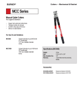
COST - Cable Tray vs. Conduit
(Equivalent Conductor Fill Areas)
Material Cost
Labor Cost @
$25/hr per NECA
labor units.
Ladder
Cable Tray
1
Solid Bottom
Cable Tray
2
EMT
3
Rigid Steel
Conduit
4
Installation: 200 linear feet of cable supported with four 90° direction changes and all
trapeze supports on 8 ft. spans.
1. Hot dip galvanized steel, 18" wide, ladder cable tray (9" rung spacing) with all hardware.
2. Hot dip galvanized steel, 18" wide, solid bottom cable tray and all hardware.
3. 7 parallel runs of 3" diameter EMT with concentric bends.
4. 7 parallel runs of 3" diameter galvanized conduit with concentric bends.
Note: Above costs are historical figures and do not include cable and cable pulling costs. Cable costs differ
per installation and cable/conductor pulling costs have been shown to be considerably less for cable
tray than for conduit.
Cooper B-Line, Inc Cable Tray Manual

• The higher the elevation of the wiring system,
the more important the number of components
required to complete the installation. Many
additional man-hours will be required just moving
the components needed for the conduit system up
to the work location.
• Conduit wiring systems require pull boxes or
splice boxes when there is the equivalent of more
than 360 degrees of bends in a run. For large
conductors, pull or junction boxes may be required
more often to facilitate the conductor’s installation.
Cable tray wiring systems do not require pull boxes
or splice boxes.
• Penetrating a masonry wall with cable tray
requires a smaller hole and limited repair work.
• More supports are normally required for rigid
steel conduit due to the requirements of NEC
®
Table 344.30(B)(2).
• Concentric conduit bends for direction changes
in conduit banks are very labor intensive and difficult
to make. However if they are not used, the
installation will be unattractive. The time required to
make a concentric bend is increased by a factor of
3-6 over that of a single shot bend. This time
consuming practice is eliminated when cable tray
wiring systems are used.
• Conductor pulling is more complicated and time
consuming for conduit wiring systems than for cable
tray wiring systems. Normally, single conductor wire
pulls for conduit wiring systems require multiple reel
setups. For conduit wiring systems, it is necessary to
pull from termination equipment enclosure to
termination equipment enclosure. Tray cables being
installed in cable trays do not have to be pulled into
the termination equipment enclosures. Tray cable
may be pulled from near the first termination
enclosure along the cable tray route to near the
second termination enclosure. Then, the tray cable
is inserted into the equipment enclosures for
termination. For projects with significant numbers of
large conductors terminating in switchgear, this may
be a very desirable feature that can save hours of an
electrician's time. Unnecessary power outages can
be eliminated since tray cable pulls may be made
without de-energizing the equipment. For conduit
installations, the equipment will have to be de-
energized for rubber safety blanketing to be
installed, otherwise the conductor pulls might have
to be made on a weekend or on a holiday at
premium labor costs to avoid shutting down
production or data processing operations during
normal working hours.
• Conductor insulation damage is common in
conduits since jamming can occur when pulling the
conductors. Jamming is the wedging of conductors
in a conduit when three conductors lay side by side
in a flat plane. This may occur when pulling around
bends or when the conductors twist. Ninety-two
percent of all conductor failures are the result of the
conductor’s insulation being damaged during the
conductor’s installation. Many common
combinations of conductors and conduits fall into
critical jam ratio values. Critical jam ratio (J.R.=
Conduit ID/Conductor OD) values range from 2.8
to 3.2. The J. R. for 3 single conductor
THHN/THWN insulated 350 kcmil conductors in a
2
1
/2 inch conduit would be 3.0 (2.469 inches/
0.816 inches). If conductor insulation damage
occurs, additional costs and time are required for
replacing the conductors. This cannot occur in a
cable tray wiring system.
• Smaller electrician crews may be used to install
the equivalent wiring capacity in cable tray. This
allows for manpower leveling, the peak and average
crew would be almost the same number, and the
electrician experience level required is lower for
cable tray installations.
• Since the work is completed faster there is less
work space conflict with the other construction
disciplines. This is especially true if installations are
elevated and if significant amounts of piping are
being installed on the project.
MAINTENANCE SAVINGS
• One of the most important features of cable
tray is that tray cable can easily be installed in
existing trays if there is space available. Cable tray
wiring systems allow wiring additions or
modifications to be made quickly with minimum
disruption to operations. Any conceivable change
that is required in a wiring system can be done at
lower cost and in less time for a cable tray wiring
system than for a conduit wiring system.
7
Cable Tray Manual Cooper B-Line, Inc

• Moisture is a major cause of electrical
equipment and material failures. Breathing due to
temperature cycling results in the conduits
accumulating relatively large amounts of moisture.
The conduits then pipe this moisture into the
electrical equipment enclosures which over a period
of time results in the deterioration of the equipment
insulation systems and their eventual failure. Also,
moisture may become a factor in the corrosion
failure of some of the critical electrical equipment's
metallic components. Conduit seals are not effective
in blocking the movement of moisture. The conduit
systems may be designed to reduce the moisture
problems but not to completely eliminate it. Few
designers go into the design detail necessary to
reduce the effects of moisture in the conduit
systems. Tray cables do not provide internal
moisture paths as do conduits.
• In the event of external fires in industrial
installations, the damage to the tray cable and cable
tray is most often limited to the area of the flame
contact plus a few feet on either side of the flame
contact area. For such a fire enveloping a steel
conduit bank, the steel conduit is a heat sink and the
conductor insulation will be damaged for a
considerable distance inside the conduit.
Thermoplastic insulation may be fused to the steel
conduit and the conduit will need to be replaced for
many feet. This occurred in an Ohio chemical plant
and the rigid steel conduits had to be replaced for
90 feet. Under such conditions, the repair cost for
fire damage would normally be greater for a conduit
wiring system than for cable tray and tray cable. In
the Ohio chemical plant fire, there were banks of
conduits and runs of cable tray involved. The cable
tray wiring systems were repaired in two days. The
conduit wiring systems were repaired in six days and
required a great deal more manpower.
• In the event of an external fire, the conduit
becomes a heat sink and an oven which decreases
the time required for the conductor insulation
systems to fail. The heat decomposes the cable
jackets and the conductor insulation material. If
these materials contain PVC as do most cables,
hydrogen chloride vapors will come out the ends of
the conduits in the control rooms. These fumes are
very corrosive to the electronic equipment. They are
also hazardous to personnel. A flame impingement
on a cable tray system will not result in the fumes
going into the control room as there is no
containment path for them. They will be dispersed
into the atmosphere
.
IN MOST CASES AN OBJECTIVE
EVALUATION OF THE REQUIREMENTS
FOR MOST HIGH DENSITY WIRING
SYSTEMS WILL SHOW THAT A CABLE
TRAY WIRING SYSTEM PROVIDES A
WIRING SYSTEM SUPERIOR TO A
CONDUIT WIRING SYSTEM.
Abandoned Cables
Easily identified, marked, or removed - all
possible from an open Cable Tray System
For the 2002 National Electrical Code, several
proposals were submitted to the NFPA to revise the
1999 NEC
®
for Articles 300, 640, 645, 725, 760,
770, 800, 820, and 830 to require all abandoned
cables to be removed from plenum spaces.
The purpose of the proposals is to remove the
cables as a source of excess combustibles from
plenums and other confined spaces such as raised
floors and drop ceilings. All of the Code Making
Panels agreed that this should be acceptable practice
except Code Making Panel 3, which oversees
Article 300.
Because Article 300 is exempt from this
requirement only low-voltage and communication
cables are affected.
Each Article adopted a definition of abandoned
cables and the rule for removal. The general
consensus is that abandoned cable is cable that is
not terminated at equipment or connectors and is
not identified for future use with a tag. Please refer
to each individual NEC
®
Article for specifics.
Having to tag, remove, or rearrange cables within
an enclosed raceway can be a time consuming and
difficult job. Without being able to clearly see the
cables and follow their exact routing throughout a
facility, identifying abandoned cables would be very
difficult and expensive.
With the open accessibility of cable tray, these
changes can be implemented with ease. Abandoned
cables can be identified, marked, rearranged, or
removed with little or no difficulty.
8
Cooper B-Line, Inc Cable Tray Manual

392.1. Scope.
Of the types of cable trays listed in this section,
ladder cable tray is the most widely used type of
cable tray due to several very desirable features.
• The rungs provide a convenient anchor for
tying down cables in vertical runs or where the
positions of the cables must be maintained in
horizontal runs.
• Cables may exit or enter through the top or the
bottom of the tray.
•A ladder cable tray without covers provides for
the maximum free flow of air, dissipating heat
produced in current carrying conductors.
• Moisture cannot accumulate in ladder cable
trays and be piped into electrical equipment as
happens in conduit systems.
• Ladder cable tray cannot pipe hazardous or
explosive gasses from one area to another as
happens with conduit systems.
• In areas where there is the potential for dust to
accumulate, ladder cable trays should be installed.
The dust buildup in ladder cable trays will be less
than the dust buildup in ventilated trough or solid
bottom cable trays.
Ladder cable trays are available in widths of 6, 9,
12, 18, 24, 30, 36, and 42 inches with rung
spacings of 6, 9, 12, or 18 inches. Wider rung
spacings and wider cable tray widths decrease the
overall strength of the cable tray. Specifiers should
be aware that some cable tray manufacturers do not
account for this load reduction in their published
cable tray load charts. B-Line uses stronger rungs in
wider cable trays to safely bear the loads published.
With one exception, the specifier selects the rung
spacing that he or she feels is the most desirable for
the installation. The exception is that 9 inches is the
maximum allowable rung spacing for a ladder cable
tray supporting any 1/0 through 4/0 single
conductor cables
[See Section 392.3(B)(1)(a)].
Where the ladder cable tray supports small
diameter multiconductor control and
instrumentation cables; 6, 9, or 12 inch rung
spacings should be specified. Quality Type TC,
Type PLTC, or Type ITC small diameter
multiconductor control and instrumentation cables
will not be damaged due to the cable tray rung
spacing selected, but the installation may not appear
neat if there is significant drooping of the cables
between the rungs.
For ladder cable trays supporting large power
cables, 9 inch or wider rung spacings should be
selected. For many installations, the cable trays are
routed over the top of a motor control center (MCC)
or switchgear enclosure. Cables exit out the bottom
of the cable trays and into the top of the MCC or
switchgear enclosure. For these installations, the
cable manufacturer's recommended minimum
bending radii for the specific cables must not be
violated. If the rung spacing is too close, it may be
necessary to remove some rungs in order to
maintain the proper cable bending radii. This
construction site modification can usually be avoided
by selecting a cable tray with 12 or 18 inch rung
spacing.
If you are still uncertain as to which rung spacing
to specify, 9 inch rung spacing is the most common
and is used on 80% of the ladder cable tray sold.
9
Standard Aluminum Ladder
AN IN-DEPTH LOOK AT 2002 NEC
®
ARTICLE 392 - CABLE TRAY
(The following code explanations are to be used with a copy of the 2002 NEC
®
.)
To obtain a copy of the NEC
®
contact:
National Fire Protection Association
®
1 Batterymarch Park • P.O. Box 9101
Quincy, Massachusetts 02269-9101
1-800-344-3555
Cable Tray Manual Cooper B-Line, Inc

The 1999 NEC
®
added the word ‘ventilated’ in
front of trough to clear up some confusion that solid
trough is treated the same as ventilated trough. It is
not. Solid trough is recognized as solid bottom cable
tray.
Ventilated trough cable tray is often used when the
specifier does not want to use ladder cable tray to
support small diameter multiconductor control and
instrumentation cables. As no drooping of the small
diameter cables is visible, ventilated trough cable
trays provide neat appearing installations. Small
diameter cables may exit the ventilated trough cable
tray through the bottom ventilation holes as well as
out the top of the cable tray. For installations where
the cables exit the bottom of the cable tray and the
system is subject to some degree of vibration, it is
advisable to use B-Line Trough Drop-Out Bushings
(Cat. No. 99-1124). These snap-in bushings provide
additional abrasion protection for the cable jackets.
Just as for ladder cable tray, ventilated trough cable
tray will not pipe moisture into electrical equipment.
Standard widths for ventilated trough cable tray
systems are 6, 9, 12, 18, 24, 30, and 36 inches.
The standard bottom configuration for ventilated
trough cable tray is a corrugated bottom with 2
7
/8
inch bearing surfaces - 6 inches on centers and 2
1
/4 inch x 4 inch ventilation openings. Since a
corrugated bottom cannot be bent horizontally, the
standard bottom configuration for horizontal bend
fittings consists of rungs spaced on 4 inch centers.
This difference in bottom construction may be
objectionable to some owners, so be sure you are
aware of the owner's sensitivity to aesthetics for the
cable tray installation.
Channel cable tray systems (B-Line's cable
channel) are available in 3, 4, and 6 inch widths
with ventilated or solid bottoms. The 2002 NEC
®
now recognizes solid bottom cable channel.
Prior to the 2002 Code, the NEC
®
did not have
any specific provisions for the use of solid cable
channel.
Instead of large conduits, cable channel may be
used very effectively to support cable drops from the
cable tray run to the equipment or device being
serviced and is ideal for cable tray runs involving a
small number of cables. Cable channel may also be
used to support push buttons, field mounted
instrumentation devices, etc. Small diameter cables
may exit ventilated cable channel through the
bottom ventilation holes, out the top or through the
end. For installations where the cables exit through
the ventilation openings and the cable channel or
the cables are subject to some degree of vibration, it
is advisable to use B-Line Cable Channel Bushings
(Cat. No. 99-1125). These snap-in plastic bushings
provide additional abrasion protection for the cable
jackets.
Some specifiers prefer solid bottom cable tray to
support large numbers of small diameter control and
multiconductor instrumentation cables. Solid bottom
steel cable trays with solid covers and wrap around
cover clamps can be used to provide EMI/RFI
shielding protection for sensitive circuits.
Unlike ladder and ventilated trough cable trays,
solid bottom cable trays can collect and retain
moisture. Where they are installed outdoors or
indoors in humid locations and EMI/RFI shielding
protection is not required, it is recommended that
1
/4 inch weep holes be drilled in their bottoms at
the sides and in the middle every 3 feet to limit
water accumulation.
10
Vent. Channel Cable Tray
(B-Line's Cable Channel)
Aluminum Solid Bottom Trough
Cooper B-Line, Inc Cable Tray Manual
Steel Ventilated Trough

The words "and other similar structures." were
incorporated in Section 392.1 for future types of
cable tray that might be developed, such as center
supported type cable tray. All the technical
information developed by the 1973 NEC
®
Technical Subcommittee on Cable Tray for Article
318 - Cable Trays was based on cable trays with
side rails and this technical information is still the
basis for the 2002 NEC
®
Article 392 - Cable Trays.
The standard lengths for cable trays are 10, 12,
20 and 24 feet (consult B-Line for the availability of
nonstandard cable tray lengths). Selecting a cable
tray length is based on several criteria. Some of
these criteria include the required load that the cable
tray must support, the distance between the cable
tray supports, and ease of handling and installation.
One industry standard that is strongly
recommended is that only one cable splice be
placed between support spans and, for long
span trays, that they ideally be place at
1
/4-span.
This automatically limits the length of tray you
choose, as the tray must be longer than or equal to
the support span you have selected. Matching the
tray length to your support span can help ensure
that your splice locations are controlled.
Cable trays can be organized into 4 categories:
Short Span, Intermediate Span, Long Span, and
Extra-Long Span.
Short Span trays, typically used for non-industrial
indoor installations, are usually supported every 6 to
8 feet, while Intermediate Span trays are typically
supported every 10 to 12 feet. A 10 or 12 foot
cable tray is usually used for both of these types of
installations. To keep from allowing two splices to
occur between supports, a 12 foot tray should be
used for any support span greater than 10 feet, up
to 12 feet. Placing the cable tray splices at
1
/4-span
is not critical in a short or intermediate span
application given that most trays have sufficiently
strong splice plates.
In an indoor industrial installation 10 or 12 foot
tray sections may be easier to handle and install as
you may have piping or ducting to maneuver
around. However, using 20 foot instead of 12 foot
straight sections may provide labor savings during
installation by reducing the number of splice joints.
If this is done, the selected tray system should meet
the loading requirements for the support span you
are using. If you are interested in supporting 100
lbs/ft and you are buying 20 foot tray sections while
supporting it every 12 feet, it isn’t necessary to
specify a NEMA 20C tray (100 lbs/ft on a 20 foot
span). A NEMA 20A tray (50 lbs/ft on a 20 foot
span) will support over 130 lbs/ft when supported
on a 12 ft span with a safety factor of 1.5.
Specifying a 20C tray is not an economical use of
product. If you desire to use 20 foot sections of
cable tray, it makes more sense to increase your
support span up to 20 feet. This not only saves
labor by decreasing the number of splices, but also
by decreasing the number of supports that must be
installed.
Long Span trays are typically supported anywhere
from 14 to 20 foot intervals with 20 feet being the
most popular. In long span situations, the placement
of the splice locations at 1/4-span becomes much
more important. Matching the tray length to your
support span can help control your splice locations.
Extra-Long Span trays are supported on spans
exceeding 20 feet. Some outdoor cable tray
installations may have to span anywhere from 20 to
30 feet to cross roads or to reduce the number of
expensive outdoor supports. The distance between
supports affects the tray strength exponentially;
therefore the strength of the cable tray system
selected should be designed around the specific
support span chosen for that run.
[See Section 392.5(A) on page 18 for additional
information on cable tray strength and rigidity.]
B-Line has many cataloged fittings and accessory
items for ladder, ventilated trough, ventilated
channel, and solid bottom cable trays which
eliminate the need for the costly field fabrication of
such items. When properly selected and installed,
these factory fabricated fittings and accessories
improve the appearance of the cable tray system in
addition to reducing labor costs.
11
Cable Tray Manual Cooper B-Line, Inc
Center Supported Cable Tray
(B-Line’s Cent-R-Rail System)

Cable Tray Materials
Metallic cable trays are readily available in aluminum,
pregalvanized steel, hot-dip galvanized after
fabrication, and stainless steel. Aluminum cable tray
should be used for most installations unless specific
corrosion problems prohibit its use. Aluminum's light
weight significantly reduces the cost of installation
when compared to steel.
A fine print note has been added in the 2002 NEC
®
that references the National Electrical Manufacturers
Association (NEMA) documents for further
information on cable tray. These documents: NEMA
VE-1, Metal Cable Tray Systems; NEMA VE-2,
Cable Tray Installation Guidelines; and NEMA FG-1,
Non Metallic Cable Tray Systems, are an excellent
industry resource in the application, selection, and
installation of cable trays both metallic and non
metallic. Contact Cooper B-Line for more
information concerning these helpful documents.
392.2. Definition. Cable Tray System.
This section states that cable tray is a rigid
structural support system used to securely fasten or
support cables and raceways. Cable trays are not
raceways. Cable trays are mechanical supports just
as strut systems are mechanical supports. NEC
®
Article 392 - Cable Trays is an article dedicated to a
type of mechanical support. It is very important that
the personnel involved with engineering and
installing cable tray utilize it as a mechanical support
system and not attempt to utilize it as a raceway
system. There are items in the NEC
®
that apply to
raceways and not to cable tray. There are also items
in the NEC
®
that apply to cable tray and not to
raceways. These differences will be covered at the
appropriate locations in this manual.
392.3. Uses Permitted. Cable tray
installations shall not be limited to
industrial establishments.
The text in Section 392.3 clearly states that cable
tray may be used in non-industrial establishments.
The use of cable tray should be based on sound
engineering and economic decisions.
For clarity, the NEC
®
now lists all types of circuits
to explicitly permit their use in cable trays. These
circuit types include: services, feeders, branch
circuits, communication circuits, control circuits, and
signaling circuits.
The 2002 NEC
®
also added a new requirement
that where cables in tray are exposed to the direct
rays of the sun, they shall be identified as sunlight
resistant for all occupancies, not just industrial.
392.3. Uses Permitted. (A) Wiring
Methods.
This section identifies the 300 & 600 volt
multiconductor cables that may be supported by
cable tray. The "Uses Permitted" or "Uses Not
Permitted" sections in the appropriate NEC
®
cable
articles provide the details as to where that cable
type may be used. Where the cable type may be
used, cable tray may be installed to support it except
as per Section 392.4 which states that cable trays
shall not be installed in hoistways or where subject
to severe physical damage. Where not subject to
severe physical damage, cable tray may be used in
any hazardous (classified) area to support the
appropriate cable types in accordance with the
installation requirements of the various Articles that
make up NEC
®
Chapter 5 or in any non-hazardous
(unclassified) area.
It should be noted that Section 300.8 of
the NEC
®
states that cable trays containing
electric conductors cannot contain any other
service that is not electrical. This includes
any pipe or tube containing steam, water, air,
gas or drainage.
For commercial and industrial cable tray wiring
systems: Type ITC, Type MC, Type TC, and Type
PLTC multiconductor cables are the most commonly
used cables. Type MI and Optical-Fiber cables are
special application cables that are desirable cables
for use in some cable tray wiring systems. The
following paragraphs provide information and
comments about these cable types.
Type MI Cable: Mineral-Insulated, Metal
Sheathed Cable (Article 332). This cable has a
liquid and gas tight continuous copper sheath over
its copper conductors and magnesium oxide
insulation. Developed in the late 1920's by the
French Navy for submarine electrical wiring systems,
properly installed MI cable is the safest electrical
wiring system available. In Europe, Type MI cable
has had a long, successful history of being installed
(with PVC jackets for corrosion protection) in cable
trays as industrial wiring systems. This cable may be
installed in hazardous (classified) areas or in non-
hazardous (unclassified) areas. The single limitation
12
Cooper B-Line, Inc Cable Tray Manual

on the use of Type MI cable is that it may not be
used where it is exposed to destructive corrosive
conditions unless protected by materials suitable for
the conditions. Type MI cable without overall
nonmetallic coverings may be installed in ducts or
plenums used for environmental air and in other
space used for environmental air in accordance with
Sections 300.22(B) and (C). Cable tray may be
installed as a support for Type MI cable in any
location except where the cable is installed in a
hoistway. Section 332-30 states that MI cable shall
be securely supported at intervals not exceeding 6
feet (1.83 m). Type MI cable has a UL two hour fire
resistive rating when properly installed. An
installation requirement for this rating is that the
cable be securely supported every 3 feet. Steel or
stainless steel cable trays should be used to support
Type MI cable being used for critical circuit service.
During severe fire conditions, steel or stainless steel
cable tray will remain intact and provide support
longer than aluminum or fiberglass reinforced plastic
cable trays.
Type MC Cable: Metal-clad cable (Article 330).
There are large amounts of Type MC cable installed
in industrial plant cable tray systems. This cable is
often used for feeder and branch circuit service and
provides excellent service when it is properly
installed. The metallic sheath may be interlocking
metal tape or it may be a smooth or corrugated
metal tube. A nonmetallic jacket is often extruded
over the aluminum or steel sheath as a corrosion
protection measure. Regular MC cable, without
nonmetallic sheath, may be supported by cable tray
in any hazardous (classified) area except Class I and
Class II, Division 1 areas. For Type MC cables to
qualify for installation in Class I and Class II Division
I areas (Section 501-4(A) (1) (c&d), they must have a
gas/vapor tight continuous corrugated aluminum
sheath with a suitable plastic jacket over the sheath.
They must also contain equipment grounding
conductors and listed termination fittings must be
used where the cables enter equipment. Type MC
Cable employing an impervious metal sheath
without overall nonmetallic coverings may be
installed in ducts or plenums used for environmental
air in accordance with Section 300.22(B) and may
be installed in other space used for environmental
air in accordance with Section 300.22(C). The
maximum support spacing is 6 feet (1.83 m).
Type TC Cable: Power and control tray cable
(Article 336). This cable type was added to the
1975 NEC
®
(as an item associated with the revision
of Article 318-Cable Trays). Type TC cable is a
multiconductor cable with a flame retardant
nonmetallic sheath that is used for power, lighting,
control, and signal circuits. It is the most common
cable type installed in cable tray for 480 volt
feeders, 480 volt branch circuits, and control
circuits. Where Type TC cables comply with the
crush and impact requirements of Type MC cable
and is identified for such use, they are permitted as
open wiring between a cable tray and the utilization
equipment or device. In these instances where the
cable exits the tray, the cable must be supported and
secured at intervals not exceeding 6 feet (See
Section 336.10(6)). The service record of UL listed
Type TC cable where properly applied and installed
has been excellent.
For those installations where the NEC
®
allows its
use, a cost savings is realized by using Type TC
cables instead of Type MC cables. Type TC cable
may be installed in cable tray in hazardous
(classified) industrial plant areas as permitted in
Articles 392, 501, 502, 504 and 505 provided the
conditions of maintenance and supervision assure
that only qualified persons will service the
installation
[See Section 336.10(3)]
.
Where a cable tray wiring system containing Type
TC cables will be exposed to any significant amount
of hot metal splatter from welding or the torch
cutting of metal during construction or maintenance
activities, temporary metal or plywood covers should
be installed on the cable tray in the exposure areas
to prevent cable jacket and conductor insulation
damage. It is desirable to use only quality Type TC
cables that will pass the IEEE 383 and UL Vertical
Flame Tests (70,000 BTU/hr). Type TC cable
assemblies may contain optical fiber members as per
the UL 1277 standard.
Type ITC Cable: Instrumentation Tray Cable
(Article 727). Although this was a new cable article
in the 1996 NEC
®
, it is not a new type of cable.
Thousands of miles of ITC cable have been installed
in industrial situations since the early 1960’s. This
is a multiconductor cable that most often has a
nonmetallic jacket. The No. 22 through No. 12
insulated conductors in the cables are 300 volt
rated. A metallic shield or a metallized foil shield
with a drain wire usually encloses the cable’s
conductors. These cables are used to transmit the
low energy level signals associated with the industrial
13
Cable Tray Manual Cooper B-Line, Inc

instrumentation and data handling systems. These
are very critical circuits that impact on facility safety
and on product quality. Type ITC cable must be
supported and secured at intervals not exceeding 6
feet
[See Section 727.4].
Type ITC Cable may be installed in cable trays in
hazardous (classified) areas as permitted in Articles
392, 501, 502, 504 and 505. It states in Article
727 that Type ITC cables that comply with the
crush and impact requirements of Type MC cable
and are identified for such use, are permitted as
open wiring in lengths not to exceed 50 ft. between
a cable tray and the utilization equipment or device.
Where a cable tray wiring system containing Type
ITC cables will be exposed to any significant amount
of hot metal splatter from welding or the torch
cutting of metal during construction or maintenance
activities, temporary metal or plywood covers should
be installed on the cable tray to prevent cable jacket
or conductor insulation damage. It is desirable to use
only quality Type ITC cables that will pass the IEEE
383 and UL Vertical Flame Tests (70,000BTU/hr).
Type PLTC Cable: Power-Limited Tray Cable
(Sections 725-61(C), and 725-71(E)). This is a
multiconductor cable with a flame retardant
nonmetallic sheath. The No. 22 through No. 12
insulated conductors in the cables are 300 volt
rated. A metallic shield or a metallized foil shield
with drain wire usually encloses the cable's
conductors. This cable type has high usage in
communication, data processing, fire protection,
signaling, and industrial instrumentation wiring
systems.
There are versions of this cable with insulation and
jacket systems made of materials with low smoke
emission and low flame spread properties which
make them desirable for use in plenums. In
Industrial Establishments where the conditions of
maintenance and supervision ensure that only
qualified persons service the installation and where
the cable is not subject to physical damage Type
PLTC cable may be installed in cable trays
hazardous (classified) areas as permitted in Section
501.4(B), 502.4(B) and 504.20. Type PLTC cables
that comply with the crush and impact requirements
of Type MC cable and are identified for such use,
are permitted as open wiring in lengths not to
exceed a total of 50 ft. between a cable tray and the
utilization equipment or device. In this situation, the
cable needs to be supported and secured at intervals
not exceeding 6 ft. Where a cable tray wiring system
containing Type PLTC cables will be exposed to any
significant amount of hot metal splatter from
welding or the torch cutting of metal during
construction or maintenance activities, temporary
metal or plywood covers should be installed on the
cable tray to prevent cable jacket and conductor
insulation damage. It is desirable to use only quality
Type PLTC cables that will pass the IEEE 383 and
UL Vertical Flame Tests (70,000 BTU/hr). Type
PLTC cable assemblies may contain optical fiber
members as per the UL 1277 standard.
Optical Fiber Cables (Article 770). The addition
of optical fiber cables in the Section 392.3(A) cable
list for the 1996 NEC was not a technical change.
Optical fiber cables have been allowed to be
supported in cable trays as per Section 770.6.
Optical fibers may also be present in Type TC
cables as per UL Standard 1277.
For the 1999 NEC
®
code, Article 760 - Fire
Alarm Cables and Articles 800 - Multipurpose and
Communications Cables were added to the list of
cables permitted to be installed in cable tray
systems.
For the 1993 NEC
®
, the general statement in the
1990 NEC
®
which allowed all types of raceways to
be supported by cable trays was replaced by
individual statements for each of the ten specific
raceway types that may now be supported by cable
tray. The chances of any such installations being
made are very low, since strut is a more convenient
and economic choice than cable tray to support
raceway systems.
392.3. Uses Permitted. (B) In Industrial
Establishments.
This section limits the installation of single
conductor cables and Type MV multiconductor
cables in cable trays to qualifying industrial
establishments as defined in this section.
Per the 2002 NEC
®
solid bottom cable trays are
now permitted to support single conductor cables
only in industrial establishments where conditions of
maintenance and supervision ensure that only
qualified persons will service the installed cable tray
system. However, at this time, no fill rules for single
conductor cables in solid bottom cable tray have
been established.
[see Section 392.3(B)]
14
Cooper B-Line, Inc Cable Tray Manual

392.3. Uses Permitted. (B) In Industrial
Establishments. (1) Single Conductor.
Section 392.3(B)(1) covers 600 volt and Type MV
single conductor cables.
There are several sections which cover the
requirements for the use of single conductor cables
in cable tray even though they only comprise a small
percentage of cable tray wiring systems. Such
installations are limited to qualifying industrial
facilities
[See Section 392.3(B)]. Many of the facility
engineers prefer to use three conductor power
cables. Normally, three conductor power cables
provide more desirable electrical wiring systems than
single conductor power cables in cable tray
(See
Section 392.8. Cable installation - three conductor vs. single
conductor cables).
392.3(B)(1)(a)
Single conductor cable shall be No. 1/0 or larger
and shall be of a type listed and marked on the
surface for use in cable trays. Where Nos. 1/0
through 4/0 single conductor cables are used, the
maximum allowable rung spacing for ladder cable
tray is 9 inches.
392.3(B)(1)(b)
Welding cables shall comply with Article 630, Part
IV which states that the cable tray must provide
support at intervals not to exceed 6 inches. A
permanent sign must be attached to the cable tray
at intervals not to exceed 20 feet. The sign must
read “CABLE TRAY FOR WELDING CABLES
ONLY”.
392.3(B)(1)(c)
This section states that single conductors used as
equipment grounding conductors (EGCs) in cable
trays shall be No. 4 or larger insulated, covered or
bare.
The use of a single conductor in a cable tray as
the EGC is an engineering design option. Section
300.3(B) states that all conductors of the same
circuit and the EGC, if used, must be contained
within the same cable tray.
The other options are to use multiconductor
cables that each contain their own EGC or to use
the cable tray itself as the EGC in qualifying
installations
[see Section 392.3(C)]
If an aluminum cable tray is installed in a moist
environment where the moisture may contain
materials that can serve as an electrolyte, a bare
copper EGC should not be used. Under such
conditions, electrolytic corrosion of the aluminum
may occur. For such installations, it is desirable to
use a low cost 600 volt insulated conductor and
remove the insulation where connections to
equipment or to equipment grounding conductors
are made.
(See Section 392.7. Grounding, for additional
information on single conductors used as the EGC for cable
tray systems).
392.3. Uses Permitted. (B) In Industrial
Establishment (2) Medium Voltage.
Single and multiconductor type MV cables (Article
328) must be sunlight resistant if exposed to direct
sunlight. Single conductors shall be installed in
accordance with 392.3(B)(1)
392.3. Uses Permitted. (C) Equipment
Grounding Conductors.
Cable tray may be used as the EGC in any
installation where qualified persons will service the
installed cable tray system. There is no restriction as
to where the cable tray system is installed. The
metal in cable trays may be used as the EGC as per
the limitations of table 392.7(B)(2). See Section
392.7. Grounding in this manual for additional
information on the use of cable trays as the EGC.
392.3. Uses Permitted. (D) Hazardous
(Classified) Locations.
This section states that if cable tray wiring systems
are installed in hazardous (classified) areas, the
cables that they support must be suitable for
installation in those hazardous (classified) areas. The
cable carries the installation restriction. The
installation restriction is not on the cable tray except
that the cable tray installations must comply with
Section 392.4. The following is an explanation of
the parts of the code which affect the use of cable
tray in hazardous locations.
501.4. Wiring Methods - Listed Termination
Fittings. (A) Class I, Division 1 (Gases or Vapors).
501-4(A)(1)(b) Type MI cable may be installed in
cable tray in this type of hazardous (classified) area.
501-4(A)(1)(c) allows Type MC-HL cables to be
installed in Class I, Division I areas if they have a
gas/vapor tight continuous corrugated aluminum
sheath with a suitable plastic jacket over the sheath.
They must also contain equipment grounding
conductors sized as per Section 250.122 and listed
termination fittings must be used where the cables
enter equipment.
15
Cable Tray Manual Cooper B-Line, Inc

501-4(A)(1)(d) allows Type ITC-HL cable to be
installed in Class I, Division I areas if they have a
gas/vapor tight continuous corrugated aluminum
sheath with a suitable plastic jacket over the sheath
and provided with termination fittings listed for the
application.
501.4. Wiring Methods. (B) Class I, Division 2
(Gases or Vapors). Types ITC, PLTC, MI, MC, MV,
or TC cables may be installed in cable tray in this
type of hazardous (classified) area. Under the
conditions specified in Section 501.5(E), Cable seals
are required in Class 1, Division 2 areas. Cable seals
should be used only when absolutely necessary.
501.5. Sealing and Drainage. (E) Cable Seals,
Class 1, Division 2. (1) Cables will be required to be
sealed only where they enter certain
types of
enclosures used in Class 1, Division 2 areas. Factory
sealed push buttons are an example of enclosures
that do not require a cable seal at the entrance of
the cable into the enclosure.
501.5. Sealing and Drainage. (E) Cable Seals,
Class 1, Division 2. (2) Gas blocked cables are
available from some cable manufacturers but they
have not been widely used. For gas to pass through
the jacketed multiconductor cable's core, a pressure
differential must be maintained from one end of the
cable to the other end or to the point where there is
a break in the cable's jacket. The existence of such a
condition is extremely rare and would require that
one end of the cable be in a pressure vessel or a
pressurized enclosure and the other end be exposed
to the atmosphere. The migration of any significant
volume of gas or vapor though the core of a
multiconductor cable is very remote. This is one of
the safety advantages that cable tray wiring systems
have over conduit wiring systems. There are
documented cases of industrial explosions caused by
the migration of gases and vapors through conduits
when they came in contact with an ignition source.
There are no known cases of cables in cable tray
wiring systems providing a path for gases or vapors
to an ignition source which produced an industrial
explosion.
501.5. Sealing and Drainage. (E) Cable Seals,
Class 1, Division 2. (3)
Exception: Cables with an unbroken gas/vapor-
tight continuous sheath shall be permitted to pass
through a Class 1, Division 2 location without
seals.
This is an extr
emely important exception stating
that cable seals are not required when a cable goes
from an unclassified area through a classified area
then back to an unclassified area.
501.5. Sealing and Drainage. (E) Cable Seals,
Class 1, Division 2. (4)
If you do not have a gas/vapor-tight continuous
sheath, cable seals are required at the boundary of
the Division 2 and unclassified location.
The sheaths mentioned above may be fabricated
of metal or a nonmetallic material.
502.4. Wiring Methods. (A) Class II, Division 1
(Combustible Dusts). Type MI cable may be
installed in cable tray in this type of hazardous
(classified) area.
The Exception allows Type MC cables to be
installed in Class II, Division 1 areas if they have a
gas/vapor tight continuous corrugated aluminum
sheath with a suitable plastic jacket over the sheath.
They must also contain equipment grounding
conductors sized as per Section 250.122 and listed
termination fittings must be used where the cables
enter equipment.
502.4. Wiring Methods. (B) Class II, Division 2
(Combustible Dusts).
This section states:
Type ITC and PLTC cables may be installed in
ladder or ventilated cable trays following the same
practices as used in non-hazardous (unclassified)
areas. No spacing is required between the ITC or
PLTC cables. This is logical as the ITC and PLTC
cable circuits are all low energy circuits which do not
produce any significant heat or heat dissipation
problems.
Type MC, MI and TC
[See Section 336.4(3)] cables
may be installed in ladder, ventilated trough, or
ventilated cable channel, but they are not allowed to
be installed in solid bottom cable trays.
Required Spacing in Cable Trays for Type MC, MI & TC
Cables in Class II, Division 2 Hazardous (Classified) Areas
16
Cooper B-Line, Inc Cable Tray Manual
D1 D1
D2
D2
D3
D2
D1
D1 D1

Note 1. The cables are limited to a single layer
with spacing between cables equal to the diameter
of the largest adjacent cable. This means that the
cables must be tied down at frequent intervals in
horizontal as well as vertical cable trays to maintain
the cable spacing. A reasonable distance between
ties in the horizontal cable tray would be
approximately 6 feet
(See Section 392.8 Cable
Installation - Tying cables to cable trays)
.
Note 2. Spacing the cables a minimum of 1 inch
from the side rails to prevent dust buildup is
recommended. This is not an NEC requirement but
a recommended practice.
Where cable tray wiring systems with current
carrying conductors are installed in a dust
environment, ladder type cable trays should be used
since there is less surface area for dust buildup than
in ventilated trough cable trays. The spacing of the
cables in dust areas will prevent the cables from
being totally covered with a solid dust layer. In dusty
areas, the top surfaces of all equipment, raceways,
supports, or cable jacket surfaces where dust layers
can accumulate will require cleanup housekeeping at
certain time intervals. Good housekeeping is
required for personnel health, personnel safety and
facility safety. Excessive amounts of dust on
raceways or cables will act as a thermal barrier
which may not allow the power and lighting
insulated conductors in a raceway or cable to safely
dissipate internal heat. This condition may result in
the accelerated aging of the conductor insulation. A
cable tray system that is properly installed and
maintained will provide a safe dependable wiring
system in dust environments.
Exception: Type MC cable listed for use in Class
II,Division I locations shall be permitted to be
installed without the above spacing limitations. This
was a new exception for the 1999 NEC
®
code.
For this type of wiring there is no danger of the
cables being overheated when covered with dust.
The current flow in these circuits is so low that the
internally generated heat is insufficient to heat the
cables and cable spacing is not a necessity. Even
under such conditions, layers of dust should not be
allowed to accumulate to critical depths as they may
be ignited or explode as the result of problems
caused by other than the electrical system.
502.4(B)(3). Nonincendive Field Wiring
Wiring in nonincendive circuits shall be permitted
using any of the wiring methods suitable for wiring
in ordinary locations.
503.3. Wiring Methods. (A) Class III, Division 1
and (B) Class III, Division 2 (Ignitable Fibers or
Flyings). Type MI or MC cables may be installed in
cable tray in these types of hazardous (classified)
areas. The installations should be made using
practices that minimize the build-up of materials in
the trays. This can be done by using ladder cable
tray with a minimum spacing between the cables
equal to the diameter of the largest adjacent cable.
In some cases, a greater spacing between cables
than that based on the cable diameters might be
desirable depending on the characteristics of the
material that requires the area to be classified. Here
again, it must be emphasized that good
housekeeping practices are required for all types of
wiring systems to insure the safety of the personnel
and the facility.
504.20. Wiring Methods. This section allows
intrinsically safe wiring systems to be installed in
cable trays in hazardous (classified) areas. Section
504.30 specifies the installation requirements for
intrinsically safe wiring systems that are installed in
cable trays. Section 504.70 specifies the sealing
requirements for cables that may be part of a cable
tray wiring system. Section 504.80(B) states that
cable trays containing intrinsically safe wiring must
be identified with permanently affixed labels.
Cable trays are ideal for supporting both
intrinsically safe and nonintrinsically safe cable
systems as the cables may be easily spaced and tied
in position or a standard metallic barrier strip may
be installed between the intrinsically and
nonintrinsically safe circuits.
505.15. Wiring Methods. This section was
added to the 2002 NEC
®
to explicitly permit cable
trays in hazardous areas classified by the
international zone system, if the cables comply with
the cable requirements for zone locations.
392.3. Uses Permitted. (E) Nonmetallic
Cable Tray.
There are limited numbers of applications where
nonmetallic cable trays might be preferred over
metallic cable trays for electrical safety reasons
and/or for some corrosive conditions. An example
of an electrical safety application would be in an
electrolytic cell room. Here, the amperages are very
high and significant stray current paths are present.
Under such conditions, there is the possibility for a
17
Cable Tray Manual Cooper B-Line, Inc

high amperage short circuit if a low resistance
metallic path (metallic cable tray or metallic raceway)
is present
[See information under Section 392.5(F)
Nonmetallic Cable Trays]
.
392.4. Uses Not Permitted.
This is the only place in the NEC
®
where all the
various types of cable tray have limitations on their
place of use. No cable trays can be used in
hoistways or where subject to severe physical
damage. The designer must identify the zones of
installation where a cable tray might be subjected to
severe physical damage. Usually such areas are
limited and provisions can be made to protect the
cable tray by relocating it to a more desirable
location or as a last resort to provide protection
using the appropriate structural members.
The second sentence of Section 392.4 states that
cable tray shall not be used in environmental air
spaces except to support the wiring methods
recognized for use in such spaces. This is not a
restriction on cable tray as long as it is used as a
support for the appropriate cable types.
Metallic cable trays may support cable types
approved for installation in Ducts or Plenums Used
for Environmental Air as per Section 300.22(B) and
the cable types approved for installation in Other
Space Used for Environmental Air as per Section
300.22(C).
The second sentence of Section 300.22(C)(1) is as
follows:
Other types of cables and conductors shall
be installed in electrical metallic tubing,
flexible metallic tubing, intermediate metal
conduit, rigid metal conduit without an
overall nonmetallic covering, flexible metal
conduit, or, where accessible, surface metal
raceway or metal wireway with metal covers
or solid bottom metal cable tray with solid
metal covers
.
Reprinted with permission from NFPA 70-1999, the National Electrical Code®,
Copyright© 1998, National Fire Protection Association, Quincy, MA 02269. This reprinted
material is not the complete and official position of the National Fire Protection Association,
on the referenced subject which is represented only by the standard in its entirety.
This part of Section 300.22(C) is confusing. The
statement as underlined in the above paragraph
leads some to assume, for installations in Other
Spaces Used for Environmental Air, that the types
of insulated single conductors which are installed in
raceway installations may also be installed in solid
bottom metal cable trays with metal covers. This is
not so. Only the appropriate multiconductor cable
types as per Section 392.3(A) may be installed in
solid bottom cable trays.
Cable tray may be used to support data process
wiring systems in air handling areas below raised
floors as per Sections 300.22(D) and 800.52(D).
392.5. Construction Specifications. (A)
Strength and Rigidity.
The designer must properly select a structurally
satisfactory cable tray for their installation. This
selection is based on the cable tray's strength, the
cable tray loading and the spacing of the supports.
The NEMA Metallic Cable Tray Systems Standard
Publication VE-1 contains the cable tray selection
information and it is duplicated in B-Line's Cable
Tray Systems Catalog.
The NEMA Standard provides for a static load
safety factor of 1.5. A number (Span in Feet - the
distance between supports) and letter (Load in lbs/ft)
designation is used to properly identify the cable
tray class on drawings, in specifications, in quotation
requisitions, and in purchase requisitions to
guarantee that the cable tray with the proper
characteristics will be received and installed. The
designer must specify the cable tray type, the
material of construction, section lengths, minimum
bend radius, width, rung spacing (for a ladder type
cable tray), and the total loading per foot for the
cables on a maximum support spacing
(See page 52
for cable tray specifications checklist)
. For many
installations, the cable trays must be selected so that
they are capable of supporting specific concentrated
loads, the weight of any equipment or materials
attached to the cable tray, ice and snow loading,
and for some installations the impact of wind
loading and/or earthquakes must be considered.
Most cable trays are utilized as continuous beams
with distributed and concentrated loads. Cable trays
can be subjected to static loads like cable loads and
dynamic loads such as wind, snow, ice, and even
earthquakes. The total normal and abnormal loading
18
Cooper B-Line, Inc Cable Tray Manual
/