Page is loading ...

OPERATION MANUAL
THIS MANUAL MUST ACCOMPANY THE EQUIPMENT AT ALL TIMES.
To find the latest revision of this
publication, visit our website at:
www.multiquip.com
Revision #0 (11/28/12)
PN 49808
MODEL MLT25 SERIES
DEDICATED LIGHT TOWER

PAGE 2 — MLT25 SERIES LIGHT TOWER • OPERATION MANUAL — REV. #0 (11/28/12)
PROPOSITION 65 WARNING
Diesel engine exhaust and some of

MLT25 SERIES LIGHT TOWER • OPERATION MANUAL — REV. #0 (11/28/12) — PAGE 3
If you believe that your vehicle has a defect that could cause a crash or could cause
injury or death, you should immediately inform the National Highway Traffic Safety
Administration (NHTSA) in addition to notifying Multiquip at 1-800-421-1244.
If NHTSA receives similar complaints, it may open an investigation, and if it finds
that a safety defect exists in a group of vehicles, it may order a recall and remedy
campaign. However, NHTSA cannot become involved in individual problems
between you, your dealer, or Multiquip.
To contact NHTSA, you may either call the Vehicle Safety Hotline toll-free at 1-888-
327-4236 (TTY: 1-800-424-9153), go to http://www.nhtsa.dot.gov; or write to:
Administrator
NHTSA
1200 New Jersey Avenue S.E.
Washington, DC 20590
You can also obtain information about motor vehicle safety from
http://www.safecar.gov.
REPORTING SAFETY DEFECTS

PAGE 4 — MLT25 SERIES LIGHT TOWER • OPERATION MANUAL — REV. #0 (11/28/12)
TABLE OF CONTENTS
MLT25 Series Light Tower
Proposition 65 Warning ........................................... 2
Reporting Safety Defects ......................................... 3
Table Of Contents .................................................... 4
Safety Information ............................................ 5-110
Specifications ........................................................ 11
Dimensions ............................................................ 12
General Information ............................................... 13
Components ..................................................... 14-15
Inspection ......................................................... 16-17
Operation .......................................................... 18-21
Maintenance ..................................................... 22-23
Maintenance — Trailers .................................... 24-26
Safety Guidelines — Trailers ............................ 27-41
Troubleshooting ................................................ 42-44
Electronic Components Locator ............................ 45
Wiring Diagram ................................................. 46-48
NOTICE
Specifications are subject to change without notice.

MLT25 SERIES LIGHT TOWER • OPERATION MANUAL — REV. #0 (11/28/12) — PAGE 5
SAFETY INFORMATION
Do not operate or service the equipment before reading the
entire manual. Safety precautions should be followed at all
times when operating this equipment. Failure to read and
understand the safety messages and operating instructions
could result in injury to yourself and others.
SAFETY MESSAGES
The four safety messages shown below will inform you
about potential hazards that could injure you or others. The
safety messages specifi cally address the level of exposure
to the operator and are preceded by one of four words:
DANGER, WARNING, CAUTION or NOTICE.
SAFETY SYMBOLS
DANGER
Indicates a hazardous situation which, if not avoided,
WILL result in DEATH or SERIOUS INJURY.
WARNING
Indicates a hazardous situation which, if not avoided,
COULD result in DEATH or SERIOUS INJURY.
CAUTION
Indicates a hazardous situation which, if not avoided,
COULD result in MINOR or MODERATE INJURY.
NOTICE
Addresses practices not related to personal injury.
SAFETY SYMBOLS
Potential hazards associated with the operation of this
equipment will be referenced with hazard symbols which
may appear throughout this manual in conjunction with
safety messages.

PAGE 6 — MLT25 SERIES LIGHT TOWER • OPERATION MANUAL — REV. #0 (11/28/12)
SAFETY INFORMATION
GENERAL SAFETY
CAUTION
NEVER operate this equipment without proper protective
clothing, shatterproof glasses, respiratory protection,
hearing protection, steel-toed boots and other protective
devices required by the job or city and state regulations.
NEVER operate this equipment when not
feeling well due to fatigue, illness or when
under medication.
NEVER operate this equipment under the infl uence of
drugs or alcohol.
ALWAYS check the equipment for loosened threads or
bolts before starting.
DO NOT use the equipment for any purpose other than
its intended purposes or applications.
NOTICE
This equipment should only be operated by trained and
qualifi ed personnel 18 years of age and older.
Whenever necessary, replace nameplate, operation and
safety decals when they become diffi cult read.
Manufacturer does not assume responsibility for any
accident due to equipment modifi cations. Unauthorized
equipment modifi cation will void all warranties.
NEVER use accessories or attachments that are not
recommended by Multiquip for this equipment. Damage
to the equipment and/or injury to user may result.
ALWAYS know the location of the nearest
fi re extinguisher.
ALWAYS know the location of the nearest
fi rst aid kit.
ALWAYS know the location of the nearest phone or
keep a phone on the job site.
Also, know the phone
numbers of the nearest ambulance, doctor and
fi re
department. This information will be invaluable in the
case of an emergency.

MLT25 SERIES LIGHT TOWER • OPERATION MANUAL — REV. #0 (11/28/12) — PAGE 7
SAFETY INFORMATION
LIGHT TOWER SAFETY
DANGER
NEVER operate the equipment in an explosive
atmosphere or near combustible materials. An
explosion or fi re could result causing severe
bodily harm or even death.
WARNING
NEVER disconnect any emergency or safety devices.
These devices are intended for operator safety.
Disconnection of these devices can cause severe injury,
bodily harm or even death. Disconnection of any of these
devices will void all warranties.
CAUTION
NEVER lubricate components or attempt service on a
running machine.
ALWAYS ensure light tower is on level ground before use
so that it cannot slide or shift around, endangering workers.
Always keep immediate area free of bystanders.
ALWAYS make sure trailer is leveled with all outriggers
extended before raising tower. Outriggers must remain
extended while tower is up.
ALWAYS keep area behind trailer clear of people while
raising and lowering mast.
NEVER remove safety pin or pull mast locking pin while
tower is in a raised position!
CHECK the mast and winch cables for wear. If any
problem occurs when lowering or raising the tower, STOP
immediately! Contact a trained technician for assistance.
NEVER pivot or retract mast while unit is operating.
NEVER use the light tower mast as a crane. DO NOT
lift anything with the mast.
NEVER attach anything to the light tower mast unless it
is an authorized Multiquip component.
ALWAYS lower the light tower when not in use, or if high
winds or electrical storms are expected.
NOTICE
ALWAYS
keep the immediate area surrounding the light
tower clean, neat, and free of debris.
ALWAYS
keep the machine in proper running condition.
Fix damage to machine and replace any broken parts
immediately.
ALWAYS
store equipment properly when it is not being
used. Equipment should be stored in a clean, dry location
out of the reach of children and unauthorized personnel.
To prevent the light tower from overturning, NEVER
use
in winds that exceed 65 mph (105 kph).
LAMP SAFETY
WARNING
NEVER attempt to replace lamp with the power on.
Always shut down the engine and turn off circuit breakers
when changing the lamp.
ALWAYS
allow a suffi cient amount of time for the lamp to
cool
before touching or changing. The possibility exists of
severe burns.
CAUTION
NEVER
use force when installing the lamp. Excessive force
could cause the lamp to break, causing bodily harm.
NOTICE
NEVER
leave any grease or oil residue on lamp surface
when replacing or removing lamp. This can create hot
spots, reducing the service life of the lamp.
ALWAYS make sure lamp surface is clean and dry.
ALWAYS replace with MQ recommended type lamp.
ALWAYS have a trained technician
install and remove
a fl oodlight, or replace any damaged fi xture wiring.

PAGE 8 — MLT25 SERIES LIGHT TOWER • OPERATION MANUAL — REV. #0 (11/28/12)
SAFETY INFORMATION
TOWING SAFETY
CAUTION
Check with your local county or state safety
towing regulations, in addition to meeting
Department of Transportation (DOT)
Safety Towing Regulations, before towing
your light tower.
In order to reduce the possibility of an accident while
transporting the light tower on public roads, ALWAYS
make sure the trailer that supports the light tower and
the towing vehicle are mechanically sound and in good
operating condition.
ALWAYS shutdown engine before transporting.
Make sure the hitch and coupling of the towing vehicle
are rated equal to, or greater than the trailer “gross
vehicle weight rating.”
ALWAYS inspect the hitch and coupling for wear. NEVER
tow a trailer with defective hitches, couplings, chains, etc.
Check the tire air pressure on both towing vehicle and
trailer. Trailer tires should be infl ated to 50 psi cold.
Also check the tire tread wear on both vehicles.
ALWAYS make sure the trailer is equipped with a safety
chain.
ALWAYS properly attach trailer’s safety chains to towing
vehicle.
ALWAYS make sure the vehicle and trailer directional,
backup, brake and trailer lights are connected and
working properly.
DOT Requirements include the following:
• Connect and test electric brake operation.
• Secure portable power cables in cable tray with tie
wraps.
The maximum speed for highway towing is 55 MPH unless
posted otherwise. Recommended off-road towing is not to
exceed 15 MPH or less depending on type of terrain.
Avoid sudden stops and starts. This can cause skidding,
or jack-knifi ng. Smooth, gradual starts and stops will
improve towing.
Avoid sharp turns to prevent rolling.
Trailer should be adjusted to a level position at all times
when towing.
Raise and lock trailer wheel stand in up position when
towing.
Place chock blocks underneath wheel to prevent
rolling
while parked.
Place support blocks
underneath the trailer’s bumper
to prevent tipping while parked.
Use the trailer’s swivel jack to adjust the trailer height to
a level position while parked.

MLT25 SERIES LIGHT TOWER • OPERATION MANUAL — REV. #0 (11/28/12) — PAGE 9
SAFETY INFORMATION
TRANSPORTING SAFETY
CAUTION
Before lifting, make sure that light tower parts are not
damaged and screws are not loosened or lost.
ALWAYS make sure crane or lifting device has been
properly secured to lifting hook of the equipment.
NEVER lift the equipment while engine is running.
Make sure the tower is in the stowed position before
lifting.
ALWAYS Make sure rear mast lock is secure before
lifting.
Use adequate lifting cable (wire or rope) of suffi cient
strength.
Use one point suspension hook and lift straight upwards.
STOWED
POSITION
LIFTING BALE
LIGHT TOWER
FORKLIFT
POCKETS
(2)
If lifting through pockets, make sure forks of forklift are
inserted in pockets as far as possible before lifting.
Never allow any person or animal to stand underneath the
equipment while lifting.
DO NOT lift equipment to unnecessary heights.
Loading and Tie-Down on Flatbed Truck
NOTICE
When loading onto fl atbed truck, make sure that front
jackstand of light tower is retracted and in the horizontal
position so that the foot does not make contact with the
deck fl oor.
Make sure that the two side (left and right) and two rear
jackstands are in the vertical postion, slightly extended,
so that each foot makes contact with the deck fl oor.
Straps and chains should be routed through the transport
tie-down points located beneath each corner of the
cabinet to allow even application of forece to the front
and rear of the machine.
DO NOT
secure the unit by running a strap or chain over
the tongue of the light tower. This may cause severe
damage to the unit.
TONGUE
FRONT
JACKSTAND
RETRACTED
TRANSPORT
TIE-DOWN
POINT
SIDE
JACK
STAND
(2)
REAR
JACK
STAND
(2)

PAGE 10 — MLT25 SERIES LIGHT TOWER • OPERATION MANUAL — REV. #0 (11/28/12)
SAFETY INFORMATION
ELECTRICAL SAFETY
DANGER
.
NEVER operate light tower
or handle any electrical
equipment while standing in
water, while barefoot, while
hands are wet or in the rain.
A dangerous electrical
shock could occur, causing
severe bodily harm or
even death.
ALWAYS make sure the
area above the light tower is
open and clear of overhead
power lines and other
obstructions. The tower
extends in excess of 30
feet (9 meters). Contact
w i t h o ve r h e a d p o w e r
lines or other obstructions
could result in equipment
damage, electrical shock,
electrocution and even
death.
Similar to boom equipment, light tower may become
energized with high voltage. DO NOT operate the light
tower within a radial distance of 17 feet from high voltage
power lines. If light tower becomes energized with high
voltage, contact with the equipment could result in
electrocution.

MLT25 SERIES LIGHT TOWER • OPERATION MANUAL — REV. #0 (11/28/12) — PAGE 11
SPECIFICATIONS
Table 1. MLT25 Series Specifications
Light Tower Specifications
Weight (with genset/trailer)
With Fuel - 4,450 lb. (2,018 kg.)
Without Fuel - 3,740 lb. (1,696 kg.)
Lamps Six 1,000-Watt Metal Halide
Lumens 660,000
Light Color Bright White
Trailer Specifications
Trailer Model TRLR75XF
Gross Vehicle Weight Rating (GVWR) 7,000 lb (3,175 kg.)
Gross Axle Weight Rating (GAWR) (ea.) 3,500 lb (1,587 kg)
Tire Size ST205/75D15 LR-C
Tire Load Rating (ea.) 1,820 lb (825 kg)
Wheel Bolt Pattern 5-Lug on 4.5 in
Fuel Tank Capacity 100 gal (378 L)
Generator/Engine Specifications
Refer to Accompanying DCA25SSIU3 Operation and Parts
Manual (Part No. 49810) for generator/engine specifications.

PAGE 12 — MLT25 SERIES LIGHT TOWER • OPERATION MANUAL — REV. #0 (11/28/12)
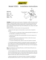
DIMENSIONS
Figure 1. Dimensions
Table 2. Dimensions
Reference Letter Description Dimension
A Length (Mast Stowed Position) 170 in. (431 cm.)
B Length (Mast Deployed Position) 101 in. (256 cm.)
C Max. Height (Mast Deployed Position) 31.5 ft. (9.6 m)
D Height (Mast Stowed Position) 74 in. (187 cm.)
E Ground Clearance (From Axle) 8 in. (20 cm.)
F Width (Tow Ready) 51 in. (129 cm.)
G Width (Outriggers Deployed) 109 in. (276 cm.)
DEPLOYED
POSITION
STOWED
POSITION
A
B
E
F
G
D
C

MLT25 SERIES LIGHT TOWER • OPERATION MANUAL — REV. #0 (11/28/12) — PAGE 13
GENERAL INFORMATION
The Multiquip MLT25 Series Light Tower is a dedicated
general purpose light tower engineered to provide
dependable lighting for a wide range of applications. This
includes lighting for construction sites, industrial locations,
special events, and emergency conditions.
METAL HALIDE LAMPS
The lighting system of the MLT25 Series Light Tower is
comprised of 6 metal halide, 1000-watt lamps. These lamps
provide maximum illumination with typical lighting coverage
of 5 to 7 acres. The lamps are controlled by individual circuit
breakers for versatility.
ENGINE
The MLT25 Series Light Tower is powered by a diesel
engine that is equipped with automatic shutdowns for
low oil pressure, high coolant temperature, and alternator
charge failure.
STABILITY
The light tower can be raised vertically in excess of 31.5
feet (9.6 meters) by means of a manual winch. The tower
tensioning system is designed to provide the necessary
tension to safely control the pivot of the tower. The light
tower has a wind stability of up to 65 mph with outriggers
and jackstands fully deployed.
PANEL LIGHT
A panel light automatically illuminates the control panel and
all functions when the engine access door is opened. This
feature is convenient for night deployment.
TRAILER DESIGN
The trailer design of the MLT25 Series light tower
withstands the rigors of the jobsite in addition to providing
smooth highway towing.

PAGE 14 — MLT25 SERIES LIGHT TOWER • OPERATION MANUAL — REV. #0 (11/28/12)
COMPONENTS
1
2
3
5
5
4
6
9
8
7
10
11
12
13
14
15
16
17
18
18
19
Figure 2 and Figure 3 show the location of the controls and
components for the MLT25 Series light tower. The function
of each control is described below.
1. Mast Rotation Locking Knob — Unscrew this knob
to release mast for rotation. Tighten this knob to lock
mast after it is set to the desired position.
2. Mast Extension Winch — Use this winch to extend
the mast to the desired height. Maximum height is
approximately 31.5 feet (9.6 meters).
3. Mast Rotation Handles — Grip these handles to rotate
mast to desired position.
4. Lifting Bale — Light tower can be lifted using this lifting
bale. The lifting bale is balanced for a fully configured
light tower. Removal of any components will unbalance
the lifting bale.
5. Forklift Pockets — Light tower can be lifted using
these forklift pockets. Insert the forks of the forklift as
far possible into the pockets.
6. Mast Cradle Support — When towing of the light
tower is required, place the tower mast into the cradle
support. Make sure cradle lock/release pin has been
inserted and mast is locked.
7. T-Bar — Allows the lamps to be mounted vertically or
horizontally.
8. Lamps — Six 1000-watt metal-halide bulbs with a
110,000 lumens capacity each. Light coverage is
typically between 5 to 7 acres.
9. Cradle Lock/Release Pin — Locks mast in cradle
support and releases mast when removed.
10. Rear Jackstands — There are two jackstands located
at the rear of the trailer. Use these jackstands to level
and support the light tower.
11. Chock Blocks — Place these blocks (not included
as part of the light tower package) under each trailer
wheel to prevent rolling.
12. Outrigger Jacks — Use these 2 outrigger jacks to
level and support the light tower. For more stability, the
outriggers can be deployed.
Figure 2. Major Components (Control Panel Side)

MLT25 SERIES LIGHT TOWER • OPERATION MANUAL — REV. #0 (11/28/12) — PAGE 15
COMPONENTS
13. Tongue Jackstand — Use this jackstand to support
the tongue when attaching the light tower to a towing
vehicle.
14. Safety Chain — Always attach safety chain to the
towing vehicle. Never tow the light tower with the safety
chain unattached.
15. Ball Hitch Coupler — Attach this coupler to the
towing vehicle. Use only the specified ball diameter
as indicated on your coupler. Use of any other ball
diameter will create an extremely dangerous condition
which can result in separation of the coupler and ball
or ball failure.
16. Vertical Mast Winch — Use this winch to raise the
mast to the vertical position.
17. Mast Lock/Release Pin — Pull this pin to start placing
the tower mast in the vertical position. When tower
mast has reached full vertical position, insert pin to
keep mast from falling.
18. Tie-Down Points — Used to tie down light tower with
strap or chains to allow even application of force to
the front and rear of the equipment during transport.
19. Fuse Block Assembly — Contains the fuses that
protect the lamp circuit breakers.
20. License Light — This light illuminates the license plate.
Whenever towing of the light tower is required, make
sure this light is operational.
21. Brake Lights — Before towing the light tower, make
sure that these lights are operational and are working
correctly. Never tow the light tower if these lights are
inoperative.
22. Engine Exhaust Pipe — Directs engine exhaust to
the rear of the light tower. NEVER block this exhaust
pipe with obstructions. ALWAYS place the generator
in an area free of obstructions.
23. Tires — This light tower uses ST205/75D15 LR-C size
tire. Replace with only recommended tire size. Never
tow light tower with bad or worn tires.
24. Circuit Breakers, 3-Pole, 15 A — Turn the lamps on
and off.
REAR VIEW FRONT VIEW
20
2121
22
23
24
Figure 3. Major Components (Front/Rear)

PAGE 16 — MLT25 SERIES LIGHT TOWER • OPERATION MANUAL — REV. #0 (11/28/12)
INSPECTION
BEFORE STARTING
1. Read all safety instructions at the beginning of
manual.
2. Clean the light tower, removing dirt and dust, particularly
the engine cooling air inlet and air cleaner.
3. Check the air filter for dirt and dust. If air filter is dirty,
replace air filter with a new one as required.
4. Check all fastening nuts and bolts for tightness.
Before starting the engine, make sure of the following:
The electrical load is disconnected and the main circuit
breaker and all lamp circuit breakers are switched to the
OFF position.
Light tower is placed on secure level ground with chock
blocks underneath each wheel to prevent the light tower
from rolling.
Outriggers have been fully extended to prevent the trailer
from tipping.
Light tower trailer support stands have been positioned
properly and the trailer is level.
Lamps have been adjusted to desired position.
Chocked blocks have been positioned under each wheel
to prevent trailer from rolling.
Light tower trailer frame has been grounded correctly.
Lamps do not interfere with any overhead obstructions.
WARNING
The engine's exhaust contains harmful
emissions. ALWAYS ventilate the exhaust
when operating inside tunnels, excavations
or buildings. Direct exhaust away from
nearby personnel.
CAUTION
NEVER start the engine with any circuit breakers in
the ON position.
Lamp power cables have been plugged into the
appropriate receptacles (J1-J6) on the T-Bar assembly.
Follow instructions below to correctly install the power
cable plugs.
a. Locate the 6 key-lock, 3-pin, female connectors on
the T-bar. See Figure 4.
Figure 4. T-Bar and Cable Connectors
DANGER
ALWAYS make sure the area above
light tower is open and clear of
overhead power lines and other
obstructions. The tower extends
in excess of 30 ft. (9 meters).
Contact with overhead power lines
or other obstructions could result in
equipment damage, serious injury
or death!
LAMP 1
LAMP 2
LAMP 3
LAMP 4
LAMP 5
LAMP 6
J1
J2
J3
J4
J5
J6
REAR
FRONT
MAST RAISED
T-BAR
FEMALE CONNECTORS
LOCKING NUT
(MALE CONNECTOR)

MLT25 SERIES LIGHT TOWER • OPERATION MANUAL — REV. #0 (11/28/12) — PAGE 17
b. Locate the key slot A on each female connector
as shown in Figure 5.
Figure 5. Female and Male Connector
c. On the corresponding male connector, locate the
key tab B as shown in Figure 5.
d. Align the key tab B on the male connector with
the key slot A on the female connector and press
together until seated.
e. Secure the connector by screwing the knurled
locking nut of the male connector to the threaded
portion of the female connector to ensure good
contact between the two connectors.
FEMALE CONNECTOR
MALE CONNECTOR
KEY TAB B
KEY SLOT A
INSPECTION

PAGE 18 — MLT25 SERIES LIGHT TOWER • OPERATION MANUAL — REV. #0 (11/28/12)
OPERATION
STARTING THE ENGINE
MAST OPERATION
Outriggers and Support Stands
See Figure 6 for location of components.
1. Make sure both outriggers are extended. To extend the
outriggers, pull the locking pin on the outrigger and hold
while sliding out the outrigger assembly.
NOTICE
Refer to the accompanying DCA25SSIU3 generator
operation and parts manual (Part Number 49810) for
information on how to start the engine.
DANGER
ALWAYS make sure the area above
light tower is open and clear of
overhead power lines and other
obstructions. The tower extends
in excess of 30 feet (9 meters).
Contact with overhead power lines
or other obstructions could result in
equipment damage, serious injury
or death!
DANGER
DO NOT stand behind
the trailer while the
mast is being raised or
lowered. Serious injury
could result if the mast
falls down.
Figure 6. Deploying Outriggers
2. As soon as the pin clears the travel position hole,
release it and continue sliding out the outrigger. The
pin must snap into the outrigger locking hole in the
extended position.
3. After extending all outriggers, rotate all trailer jack
stands into the foot down position, then turn the crank
handle on the jackstands clockwise to lower it and level
the light tower.
4. Check behind the light tower and make sure all
personnel and objects are clear of the mast.
Deploying the Mast to Vertical Position
Refer to Figure 7 for the location of components:
1. To release the mast from the mast cradle support, pull
the retaining pin out of the cradle lock/release pin. Pull
the cradle lock/release pin. This will unlock the mast
from the horizontal position.
2. Remove the mast lock/release pin before raising tower
to the vertical position.
3. To place the mast in the vertical position, turn the
vertical mast winch hand lever clockwise until the mast
is pointing upwards at 90 degrees.
4. Once the mast is in the vertical position, insert the
mast lock/release pin to prevent the mast from falling.
PULL OUTRIGGER
TO EXTEND
PULL PIN TO
RELEASE
OUTRIGGER
ROTATE
JACKSTAND
TO PLACE
IN SUPPORT
POSITION
OUTRIGGER
JACKSTAND

MLT25 SERIES LIGHT TOWER • OPERATION MANUAL — REV. #0 (11/28/12) — PAGE 19
Figure 7. Raising the Mast
MAST ROTATION
HANDLE (2)
MAST
ROTATION
LOCKING
KNOB
CRADLE
LOCK/RELEASE
LEVER
MAST
CRADLE SUPPORT
MAST LOCK
HANDLE
MAST LOCK/RELEASE PIN
OPERATION

PAGE 20 — MLT25 SERIES LIGHT TOWER • OPERATION MANUAL — REV. #0 (11/28/12)
OPERATION
Raising the Mast
Once the tower mast has been locked into its vertical
position, the mast can now be raised. The tower allows the
lamps to be extended upwards in excess of 30 feet.
Refer to Figure 7 for location of components.
1. Turn the mast extension winch clockwise and observe
that the mast begins to extend upwards.
2. Continue turning the winch in the clockwise direction
until the desired height has been reached.
3. Release the winch. This winch is of the self-locking
type. The tension on the cable will keep the mast in
place.
Lowering the Mast
1. Turn the mast extension winch counterclockwise, and
observe that the mast begins to lower.
2. Continue turning the winch counterclockwise until the
mast has been fully retracted (slack in the cable).
Stowing the Mast to Horizontal Position
Refer to Figure 7 for the location of components:
1. Remove the mast lock/release pin to allow the mast
section to be lowered to the horizontal position. Pull
out the mast lock handle to unlatch.
2. Turn the vertical mast winch counterclockwise and
observe that mast begins to approach the horizontal
position. The mast lock handle can now be released.
3. Continue turning the vertical mast winch in the
counterclockwise direction. As the mast approaches
the mast cradle support, pull the retaining pin and
then the cradle lock/release pin to allow the mast to
rest in the cradle.
4. Once the mast is resting in the mast cradle support,
insert the cradle lock/release pin and secure with
retaining pin to keep mast in place.
Rotating the Mast
To change the direction that the lamps are facing, the mast
can be rotated.
Refer to Figure 7 for the location of components.
1. With the mast in the deployed position (vertical),
unscrew the mast rotation locking knob to release the
mast for rotation.
2. Grip the mast rotation handles and rotate the mast until
the lamps are facing the desired direction.
3. When the lamps are facing the desired direction,
tighten the mast rotation lock knob to lock the mast
in place.
TURNING ON THE LAMPS
Three lamp circuit breakers (15 amps each) are located
on the front of the light tower to turn the lamps on and off.
The lamps can be turned on with the voltage selector
in three different positions. See Table 3 for the different
settings.
1. Before turning on the lamps, make sure that main circuit
breaker on the generator control panel and the circuit
breakers shown in Figure 8 are all in the off position.
Figure 8. Lamp Circuit Breakers
Table 3. Lamp Settings
Voltage
Selector
Switch
Setting
Voltage
Regulator
Setting
Circuit
Breaker
(ON)
Lamps
(ON)
1 PHASE
240/120
240V
CB1 1 & 3
CB2 4 & 6
CB3 2 & 5
3 PHASE
240/139
208V
CB1 1, 2, & 3
CB2 4, 5, & 6
3 PHASE
480/277
480 V
CB3 N/A
CB1
OFF
CB2 CB3
ON
/