Page is loading ...

Instruction Manual
760009-B
November 2002
http://www.processanalytic.com
Model NGA2000 WNX and WCLD
Wet NOx Sample Conversion Module and
Wet CLD Analyzer Module

Emerson Process Management
Rosemount Analytical Inc.
Process Analytic Division
1201 N. Main St.
Orrville, OH 44667-0901
T (330) 682-9010
F (330) 684-4434
e-mail: [email protected]
http://www.processanalytic.com
ESSENTIAL INSTRUCTIONS
READ THIS PAGE BEFORE PROCEEDING!
Rosemount Analytical designs, manufactures and tests its products to meet many national and in-
ternational standards. Because these instruments are sophisticated technical products, you
MUST properly install, use, and maintain them
to ensure they continue to operate within their
normal specifications. The following instructions MUST be adhered to and integrated into your
safety program when installing, using, and maintaining Rosemount Analytical products. Failure to
follow the proper instructions may cause any one of the following situations to occur: Loss of life;
personal injury; property damage; damage to this instrument; and warranty invalidation.
• Read all instructions
prior to installing, operating, and servicing the product.
• If you do not understand any of the instructions, contact your Rosemount Analytical rep-
resentative for clarification.
• Follow all warnings, cautions, and instructions marked on and supplied with the product.
• Inform and educate your personnel in the proper installation, operation, and maintenance of
the product.
• Install your equipment as specified in the Installation Instructions of the appropriate Instruc-
tion Manual and per applicable local and national codes. Connect all products to the proper
electrical and pressure sources.
• To ensure proper performance, use qualified personnel
to install, operate, update, program,
and maintain the product.
• When replacement parts are required, ensure that qualified people use replacement parts
specified by Rosemount. Unauthorized parts and procedures can affect the product’s per-
formance, place the safe operation of your process at risk, and VOID YOUR WARRANTY
.
Look-alike substitutions may result in fire, electrical hazards, or improper operation.
• Ensure that all equipment doors are closed and protective covers are in place, except when
maintenance is being performed by qualified persons, to prevent electrical shock and per-
sonal injury.
The information contained in this document is subject to change without notice.
Teflon is a Registered Trademark of E.I. duPont de Nemours and Co., Inc.
Kynar is a Registered Trademark of Atochem North America, Inc.

Instruction Manual
760009-B
November 2002
Rosemount Analytical Inc. A Division of Emerson Process Management Contents i
Model NGA2000 WNX and WCLD
TABLE OF CONTENTS
PREFACE...........................................................................................................................................P-1
Definitions ...........................................................................................................................................P-1
Safety Summary .................................................................................................................................P-2
General Precautions For Handling And Storing High Pressure Gas Cylinders .................................P-5
Documentation....................................................................................................................................P-6
Compliances .......................................................................................................................................P-6
Glossary..............................................................................................................................................P-7
1.0 DESCRIPTION AND SPECIFICATIONS..............................................................................1-1
1-1 Overview...................................................................................................................................1-1
1-2 Typical Applications..................................................................................................................1-1
1-3 Specifications – Wet NOx Conversion Module ........................................................................1-6
a. Performance ...............................................................................................................1-6
b. Physical.......................................................................................................................1-6
c. Sample ........................................................................................................................1-6
d. Gas Connections ........................................................................................................1-6
1-4 Specifications - Wet CLD Analyzer Module .............................................................................1-7
a. Performance ...............................................................................................................1-7
b. Physical.......................................................................................................................1-7
c. Sample ........................................................................................................................1-7
d. Gas Connections ........................................................................................................1-8
2.0 INSTALLATION ....................................................................................................................2-1
2-1 Unpacking.................................................................................................................................2-1
2-2 Modification of a Conventional CLD for use in a WNX System ...............................................2-1
2-3 Assembly ..................................................................................................................................2-1
2-4 Location ....................................................................................................................................2-1
2-5 Gases .......................................................................................................................................2-2
a. Overview .....................................................................................................................2-2
b. Pneumatic Connections ..............................................................................................2-2
c. Specifications ..............................................................................................................2-2
2-6 Electrical Connections..............................................................................................................2-5
3.0 OPERATION .........................................................................................................................3-1
3-1 Overview...................................................................................................................................3-1
3-2 Displays & Operating Keys.......................................................................................................3-1
a. Menu Lines & Softkey Functionality............................................................................3-1
b. Common Function Keys..............................................................................................3-2
c. Entering & Changing Variables...................................................................................3-3
d. Starting a Function......................................................................................................3-3
e. Measure Mode Display ...............................................................................................3-4
f. Main Menu ...................................................................................................................3-4
3-3 Startup & Initialization...............................................................................................................3-7
a. Startup Procedure.......................................................................................................3-7
b. Warm-up of the WNX Module.....................................................................................3-8
c. Warm-up of the WCLD Module...................................................................................3-8

Instruction Manual
760009-B
November 2002
ii Contents Rosemount Analytical Inc. A Division of Emerson Process Management
Model NGA2000 WNX and WCLD
d. Binding ........................................................................................................................3-8
3-4 Routine Operation ....................................................................................................................3-8
3-5 Basic Controls and Status ........................................................................................................3-8
a. Analyzer Channel Status ............................................................................................3-9
b. Single Component Display..........................................................................................3-9
c. Multi Component Display ............................................................................................3-9
d. Basic Controls.............................................................................................................3-9
3-6 Display Controls .......................................................................................................................3-10
3-7 Analyzer And I/O, Expert Controls And Setup .........................................................................3-11
a. Range Settings ...........................................................................................................3-12
b. Physical Measurements..............................................................................................3-12
c. Concentration Alarms..................................................................................................3-13
d. Linearization Parameters............................................................................................3-13
e. Linearization Functions ...............................................................................................3-14
f. Response Time............................................................................................................3-16
g. Automatic Range Change...........................................................................................3-17
h. Display Units ...............................................................................................................3-17
i. Physical Measurements & Pressure Limits..................................................................3-18
j. Single Component Display Parameters.......................................................................3-19
3-8 Calibration Procedure...............................................................................................................3-20
a. Calibration Setup ........................................................................................................3-20
b. Basic Controls Calibration...........................................................................................3-22
c. Expert Controls Calibration .........................................................................................3-22
d. Unable to Calibrate .....................................................................................................3-24
3-9 System & Network I/O Module Controls (Setup) – System SIO .............................................3-25
a. Analog Output Setup...................................................................................................3-26
b. Serial interface setup ..................................................................................................3-28
c. Relay Outputs Setup ...................................................................................................3-29
3-10 System & Network I/O Module Controls (Setup) – System DIO ...........................................3-30
3-11 System Configuration and Diagnostics ..................................................................................3-30
a. Diagnostic Menus .......................................................................................................3-31
b. Load/Save Module Configuration ...............................................................................3-33
c. Date and Time.............................................................................................................3-33
d. Security Codes............................................................................................................3-34
e. System Reset..............................................................................................................3-35
3-12 Converter Temperature Adjustment.......................................................................................3-35
3-13 Measurement of Converter Efficiency ....................................................................................3-36
a. Test Setup for Measurement of Conversion Efficiency ..............................................3-36
b. Test Procedure ...........................................................................................................3-36
c. Subnormal Conversion Efficiency ...............................................................................3-38
d. Replacement of Converter ..........................................................................................3-38
e. Capillaries ...................................................................................................................3-38
f. TEA Scrubber ..............................................................................................................3-38
4.0 MAINTENANCE AND SERVICE – WET NOX .....................................................................4-1
4-1 Overview...................................................................................................................................4-1
4-2 Power Fuse ..............................................................................................................................4-1
4-3 Peristaltic Pump .......................................................................................................................4-3
a. Peristaltic Pump - Replacement .................................................................................4-3
b. Replacing Peristaltic Pump Tube................................................................................4-4
4-4 Oven Components ...................................................................................................................4-5
a. Converter Thermostat .................................................................................................4-5
b. Manifold Thermistor and Case Thermistor .................................................................4-5

Instruction Manual
760009-B
November 2002
Rosemount Analytical Inc. A Division of Emerson Process Management Contents iii
Model NGA2000 WNX and WCLD
c. Temperature Sensor ...................................................................................................4-5
d. Converter .....................................................................................................................4-6
e. Oven Fan ....................................................................................................................4-8
f. Regulator/Manifold Assembly ......................................................................................4-9
4-5 LON/Power Module ..................................................................................................................4-11
4-6 Power Module ..........................................................................................................................4-11
4-7 Electronics Assembly ...............................................................................................................4-11
a. Computer Board..........................................................................................................4-13
b. Module Function Board...............................................................................................4-13
4-8 Exhaust Fan .............................................................................................................................4-14
a Exhaust Fan Screen ....................................................................................................4-14
4-9 Intake Fan.................................................................................................................................4-15
4-10 Dehumidifier ...........................................................................................................................4-16
5.0 MAINTENANCE AND SERVICE – WET CLD......................................................................5-2
5-1 Power Fuse Replacement........................................................................................................5-2
5-2 Fans..........................................................................................................................................5-4
a. Fan Replacement........................................................................................................5-4
b. Cleaning EMI Filters....................................................................................................5-4
5-3 Transistor Assembly Replacement ..........................................................................................5-4
5-4 Ozone Generator......................................................................................................................5-4
a. Preventive Maintenance .............................................................................................5-4
b. Replacing ....................................................................................................................5-4
5-5 Ozone Generator Power Supply Replacement......................................................................5-4
5-6 Replacing Printed Circuit Boards .............................................................................................5-6
a. Computer Board..........................................................................................................5-6
b. Signal Board ...............................................................................................................5-7
c. Driver Board ................................................................................................................5-7
d. Power Supply Board ...................................................................................................5-9
e. LON/Power Module.....................................................................................................5-10
5-7 Prom .........................................................................................................................................5-11
5-8 Pressure Switch Replacement .................................................................................................5-12
5-9 Detector ....................................................................................................................................5-13
a. Removing Detector from Analyzer Module .................................................................5-14
b. Replacing Detector Components................................................................................5-14
5-10 Vent and Pump Capillaries.....................................................................................................5-20
5-11 Sample and Ozone Pressure Sensors...................................................................................5-20
5-12 Cleanup of WCLD due to Carryover of Water from WNX Module. ........................................5-21
6.0 REPLACEMENT PARTS ......................................................................................................6-1
6-1 Matrix........................................................................................................................................6-1
6-2 WNX .........................................................................................................................................6-2
a. 656715 Converter .......................................................................................................6-2
b. 656769 Dehumidifier...................................................................................................6-2
6-3 WCLD .......................................................................................................................................6-2
a. Detector.......................................................................................................................6-2
7.0 RETURN OF MATERIAL......................................................................................................7-1
7-1 Return of Material.....................................................................................................................7-1
7-2 Customer Service.....................................................................................................................7-1
7-3 Training.....................................................................................................................................7-1
8.0 INDEX....................................................................................................................................8-1

Instruction Manual
760009-B
November 2002
iv Contents Rosemount Analytical Inc. A Division of Emerson Process Management
Model NGA2000 WNX and WCLD
LIST OF ILLUSTRATIONS
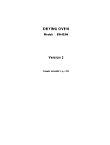
Figure 1-1. WNX Module Flow System ..........................................................................................1-2
Figure 1-2. WNX Module – Major Components .............................................................................1-3
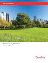
Figure 1-3. WCLD Module Flow Diagram ......................................................................................1-4
Figure 1-4. WCLD Module – Major Components ...........................................................................1-5
Figure 2-1. Rear Panel Connections of the WNX Module..............................................................2-4
Figure 2-2. Rear Panel Connections of the WCLD Module ...........................................................2-4
Figure 2-3. WNX Intake Fan Location ............................................................................................2-4
Figure 2-4. Electrical Connections..................................................................................................2-5
Figure 2-5. WNX - Outline and Mounting Dimensions ...................................................................2-6
Figure 2-6. WCLD - Outline and Mounting Dimensions .................................................................2-7
Figure 2-7. WNX - Wiring Diagram.................................................................................................2-8
Figure 2-8. WCLD – Wiring Diagram............................................................................................2-9
Figure 3-1. Measure Mode Display ................................................................................................3-1
Figure 3-2. The Display Screen......................................................................................................3-3
Figure 3-3. Changing Variables......................................................................................................3-3
Figure 3-4. Function Confirmation..................................................................................................3-3
Figure 3-5. Main Menu Functions...................................................................................................3-4
Figure 3-6. Module Manufacturing Data Displays ..........................................................................3-5
Figure 3-7. Main Menu Sub Menus ................................................................................................3-6
Figure 3-8. Startup Display.............................................................................................................3-7
Figure 3-9. Basic Controls Menu....................................................................................................3-9
Figure 3-10. Display Controls Menu...............................................................................................3-10
Figure 3-11. Analyzer and I/O Expert Controls and Setup Menu...................................................3-11
Figure 3-12. Expert Controls Menu ................................................................................................3-11
Figure 3-13. Range Settings Menu ................................................................................................3-12
Figure 3-14. Physical Measurements Menu...................................................................................3-12
Figure 3-15. Concentration Alarm Setup Menu..............................................................................3-13
Figure 3-16. Linearization Parameters Menu .................................................................................3-13
Figure 3-17. Linearity Coefficients Menu........................................................................................3-14
Figure 3-19. Polynomial Setup Menu .............................................................................................3-14
Figure 3-20. Gas Concentrations Menu .........................................................................................3-15
Figure 3-21. Midpoint Correction Setup Menu ...............................................................................3-15
Figure 3-22. Response time/delay Parameters..............................................................................3-16
Figure 3-23. Automatic Range Control Menu.................................................................................3-17
Figure 3-24. Actual Switch Levels Menu ........................................................................................3-17
Figure 3-25. Display Units Menu ....................................................................................................3-17
Figure 3-26. Physical Measurements Menu...................................................................................3-18
Figure 3-27. Pressure Limits Menu ................................................................................................3-18
Figure 3-28. Temperature Limits Menu ..........................................................................................3-18
Figure 3-29. Physical Measurements – Manufacturer’s settings Display ......................................3-19
Figure 3-30. Displayed Parameters Menu......................................................................................3-19
Figure 3-31. Calibration Gas List Menu..........................................................................................3-21
Figure 3-32. Calibration Parameters Display .................................................................................3-21
Figure 3-33. Analyzer Zero Display ................................................................................................3-22
Figure 3-34. Expert Controls Menu ................................................................................................3-22
Figure 3-35. Zero/Span Calibration Menu ......................................................................................3-23
Figure 3-36. Analyzer Zero Menu...................................................................................................3-23
Figure 3-37. Zero/Span Diagnostic Data Menu..............................................................................3-23
Figure 3-38. Calibration Factors Menu...........................................................................................3-24

Instruction Manual
760009-B
November 2002
Rosemount Analytical Inc. A Division of Emerson Process Management Contents v
Model NGA2000 WNX and WCLD
Figure 3-39. Range Factors Menu..................................................................................................3-24
Figure 3-40. Range Factors Display...............................................................................................3-24
Figure 3-41. System & Network I/O Module Controls Menu ..........................................................3-25
Figure 3-42. System SIO Module Menu .........................................................................................3-25
Figure 3-43. Analog Output Setup Menu........................................................................................3-26
Figure 3-44. Analog Output Setup Menu........................................................................................3-26
Figure 3-45. Signals Menu ............................................................................................................3-26
Figure 3-46. Output Signal If Assigned Module Fails Menu...........................................................3-27
Figure 3-47. Special Scaling for Concentration Signal Menu.........................................................3-28
Figure 3-48. Analog Output Updates per Second Menu ................................................................3-28
Figure 3-49. Serial Interface Setup Menu ......................................................................................3-28
Figure 3-50. AK Protocol Definitions Menu ....................................................................................3-29
Figure 3-51. Relay Outputs Setup Menu........................................................................................3-29
Figure 3-52. Choose Source Module Menu ...................................................................................3-29
Figure 3-53. Choose Signal Menu..................................................................................................3-29
Figure 3-55. System Configuration and Diagnostics Menu............................................................3-30
Figure 3-56. Diagnostic Menu ........................................................................................................3-31
Figure 3-57. Analyzer Diagnostics Menu .......................................................................................3-31
Figure 3-58. Power Supply Voltages Menu....................................................................................3-31
Figure 3-59. Primary Variable Parameters Menu...........................................................................3-31
Figure 3-60. Physical Measurements Menu...................................................................................3-32
Figure 3-61. Temperature Control Menu (Screen 1)......................................................................3-32
Figure 3-62. Temperature Control Menu (Screen 2)......................................................................3-32
Figure 3-63. NO/NOx Flow Balance Menu.....................................................................................3-32
Figure 3-64. Calculate Factor Using Pressure Ratio Menu............................................................3-33
Figure 3-65. Load/Save Configuration (CM/MCA) Menu ...............................................................3-33
Figure 3-66. Date and Time Menu..................................................................................................3-33
Figure 3-67. Security Codes Menu.................................................................................................3-34
Figure 3-68. Define Basic Level Security PIN Menu ......................................................................3-34
Figure 3-69. System Reset Menu...................................................................................................3-35
Figure 3-70. Measuring Efficiency of NO
2
to NO Converter...........................................................3-39
Figure 3-71. Conversion Efficiency as a Function of Converter Temperature ...............................3-40
Figure 4-1. WNX - Power Fuse Location........................................................................................4-1
Figure 4-2. WNX - Removing Module Cover..................................................................................4-3
Figure 4-3. WNX - Replacing Peristaltic Pump ..............................................................................4-3
Figure 4-4. WNX - Replacing Peristaltic Pump Tube .....................................................................4-4
Figure 4-5. WNX - Removing Converter Thermostat, Manifold Thermistor Temperature Sensor
and Converter..............................................................................................4-6
Figure 4-6. WNX Converter Assembly ...........................................................................................4-7
Figure 4-7. WNX - Removal of Oven Fan ......................................................................................4-8
Figure 4-8. WNX - Removing Rear Panel ......................................................................................4-9
Figure 4-9. WNX - Removing Regulator/Manifold Assembly .........................................................4-10
Figure 4-10. WNX - Regulator/Manifold Assembly.........................................................................4-11
Figure 4-11. WNX - Removing LON/Power Module, Power Module and Electronics Assembly ...4-12
Figure 4-12. WNX - Electronics Assembly (Exploded View)..........................................................4-13
Figure 4-13. WNX - Removal of Exhaust Fan and Screen ............................................................4-14
Figure 4-14. WNX - Removal of Intake Fan ...................................................................................4-15
Figure 4-15. WNX - Removal of Dehumidifier ................................................................................4-16
Figure 5-1. WCLD Power Fuse Location........................................................................................5-4
Figure 5-2. WCLD - Removing Cover ............................................................................................5-3
Figure 5-3. WCLD - Removal of Intake and Exhaust Fans ............................................................5-3
Figure 5-4. WCLD - Removal of Ozone Generator, Ozone Generator Power Supply, and
Transistor Assembly ....................................................................................5-6

Instruction Manual
760009-B
November 2002
vi Contents Rosemount Analytical Inc. A Division of Emerson Process Management
Model NGA2000 WNX and WCLD
Figure 5-5. WCLD - Removing Computer Board and Bracket From Analyzer Module..................5-6
Figure 5-6. WCLD – Removing Computer Board From Bracket ....................................................5-7
Figure 5-7. WCLD – Removing Signal Board, Driver Board ..........................................................5-8
Figure 5-8. WCLD - Removing Power Supply/LON Assembly from Analyzer Module ..................5-9
Figure 5-9. WCLD - Power Supply Board/LON Power Module Assembly .....................................5-10
Figure 5-10. WCLD - PROM Location on Computer Board ...........................................................5-11
Figure 5-11. WCLD - Removing Pressure Switch and Detector from Analyzer Module................5-12
Figure 5-12. WCLD Detector – Cutaway View ...............................................................................5-13
Figure 5-13. WCLD - Removing Heater Thermostat Assembly from Detector ..............................5-14
Figure 5-14. WCLD - Removing Reaction Chamber and Sapphire Window from Detector...........5-15
Figure 5-15. WCLD - Removing the Photodiode from the Detector...............................................5-16
Figure 5-16. WCLD - Photodiode/Socket (Exploded View)............................................................5-17
Figure 5-17. WCLD - Capillary Assembly.......................................................................................5-18
Figure 5-18. WCLD - Removing the Sample Capillary from the Detector......................................5-19
Figure 5-19. WCLD - Replacing Pressure Sensors........................................................................5-20

Instruction Manual
760009-B
November 2002
Rosemount Analytical Inc. A Division of Emerson Process Management Description and Specifications P-1
Model NGA2000 WNX and WCLD
PREFACE
The purpose of this manual is to provide information concerning the components,
functions, installation and maintenance of the NGA 2000 CLD and the System Accessories
of the NGA 2000 System.
Some sections may describe equipment not used in your configuration. The user should
become thoroughly familiar with the operation of this module before operating it. Read
this instruction manual completely.
DEFINITIONS
The following definitions apply to DANGERS, WARNINGS, CAUTIONS and NOTES found throughout
this publication.
DANGER .
Highlights the presence of a hazard which will cause severe personal injury, death, or substantial
property damage if the warning is ignored.
WARNING .
Highlights an operation or maintenance procedure, practice, condition, statement, etc. If not
strictly observed, could result in injury, death, or long-term health hazards of personnel.
CAUTION.
Highlights an operation or maintenance procedure, practice, condition, statement, etc. If not
strictly observed, could result in damage to or destruction of equipment, or loss of effectiveness.
NOTE
Highlights an essential operating procedure,
condition or statement.

Instruction Manual
760009-B
November 2002
P-2 Rosemount Analytical Inc. A Division of Emerson Process Management
Model NGA2000 WNX and WCLD
SAFETY SUMMARY
If this equipment is used in a manner not specified in these instructions, protective systems may be im-
paired.
AUTHORIZED PERSONNEL
To avoid explosion, loss of life, personal injury and damage to this equipment and on-site property,
all personnel authorized to install, operate and service the this equipment should be thoroughly
familiar with and strictly follow the instructions in this manual. SAVE THESE INSTRUCTIONS.
DANGER.
ELECTRICAL SHOCK HAZARD
Do not operate without doors and covers secure. Servicing requires access to live parts which can
cause death or serious injury. Refer servicing to qualified personnel. For safety and proper per-
formance this instrument must be connected to a properly grounded three-wire source of power.
WARNING .
TOXIC AND OXIDIZING GAS
This module generates ozone which is toxic by inhalation and is a strong irritant to throat and
lungs. Ozone is also a strong oxidizing agent. Its presence is detected by a characteristic pungent
odor.
The module's exhaust contains both ozone and nitrogen dioxide, both toxic by inhalation, and may
contain other constituents of the sample gas which may be toxic. Such gases include various ox-
ides of nitrogen, unburned hydrocarbons, carbon monoxide and other products of combustion re-
actions. Carbon monoxide is highly toxic and can cause headache, nausea, loss of consciousness,
and death.
Avoid inhalation of the ozone produced within the module, and avoid inhalation of the sample and
exhaust products transported within the module. Avoid inhalation of the combined exhaust prod-
ucts at the exhaust fitting.
Keep all tube fittings tight to avoid leaks The user is responsible for testing for leakage only at the
inlet and outlet fittings on the rear panel. Periodically, the user should do an internal leak test (with
a test procedure chosen by the user).
Connect rear exhaust outlet to outside vent with stainless steel or Teflon line. Check vent line and
connections for leakage.

Instruction Manual
760009-B
November 2002
Rosemount Analytical Inc. A Division of Emerson Process Management Description and Specifications P-3
Model NGA2000 WNX and WCLD
WARNING.
PARTS INTEGRITY
Tampering or unauthorized substitution of components may adversely affect safety of this product.
Use only factory documented components for repair.
WARNING.
OVERBALANCE HAZARD
This analyzer module may tip instrument over if it is pulled out too far and the Platform is not prop-
erly supported.
WARNING.
INTERNAL ULTRAVIOLET LIGHT
Ultraviolet light from the ozone generator can cause permanent eye damage. Do not look directly at
the ultraviolet source. Use of ultraviolet filtering glasses is recommended.
WARNING.
TOXIC CHEMICAL HAZARD
The ozone generator lamp contains mercury. Lamp breakage could result in mercury exposure.
Mercury is highly toxic if absorbed through the skin or ingested, or if vapors are inhaled.
Handle lamp assembly with extreme care. If the lamp is broken, avoid skin contact and inhalation
in the area of the lamp or the mercury spill.
Immediately clean up and dispose of the mercury spill and lamp residue as follows:
• Wearing rubber gloves and goggles, collect all droplets of mercury by means of a suction pump
and aspirator bottle with a long capillary tube. (Alternately, a commercially available mercury
spill clean-up kit, such as J.T. Baker product No. 4439-01, is recommended.)
• Carefully sweep any remaining mercury and lamp debris into a dust pan. Carefully transfer all
mercury, lamp residue and debris into a plastic bottle which cab be tightly capped.
• Label and return to hazardous material reclamation center. Do not place in the trash, incinerate
or flush down the sewer.
• Cover any fine droplets of mercury in non-accessible crevices with calcium polysulfide and sul-
fur dust

Instruction Manual
760009-B
November 2002
P-4 Rosemount Analytical Inc. A Division of Emerson Process Management
Model NGA2000 WNX and WCLD
WARNING.
HAND INJURY HAZARD
Do not place hands or fingers in the Platform front handles when front panel is open. Dropping the
front panel of the Platform while hand or fingers are inside either handle can cause serious injury.
CAUTION .
PRESSURIZED GAS
This module requires periodic use of pressurized gas. See General Precautions for Handling and
Storing High Pressure Gas Cylinders, page P-5
CAUTION.
STATIC SENSITIVE COMPONENTS
Circuit boards in this instrument are static-sensitive. Take all static precautions when handling
them.
NOTICE
Software compatibility is necessary for all NGA 2000 components in your system to work together.
The version of your Platform's software must be equal to or greater that the version of any other
module(s) for successful compatibility. If it is not, contact Rosemount Analytical at 800-433-6076 to
order software upgrade kit PN NL657150 for the Platform.
You can locate the version of each NGA 2000 component as follows:
Platform Controller Board
Turn power ON.
The display will show "Control Module V2. ...". This is the software version.
Analyzer Module
Located on the right side of the Analyzer Module case.
I/O Module
Located on the backplane connector of the module. If no label is present, the module is Version
2.0.

Instruction Manual
760009-B
November 2002
Rosemount Analytical Inc. A Division of Emerson Process Management Description and Specifications P-5
Model NGA2000 WNX and WCLD
GENERAL PRECAUTIONS FOR HANDLING AND STORING HIGH
PRESSURE GAS CYLINDERS
Edited from selected paragraphs of the Compressed Gas Association's "Handbook of Compressed
Gases" published in 1981
Compressed Gas Association
1235 Jefferson Davis Highway
Arlington, Virginia 22202
Used by Permission
1. Never drop cylinders or permit them to strike each other violently.
2. Cylinders may be stored in the open, but in such cases, should be protected against extremes of weather
and, to prevent rusting, from the dampness of the ground. Cylinders should be stored in the shade when lo-
cated in areas where extreme temperatures are prevalent.
3. The valve protection cap should be left on each cylinder until it has been secured against a wall or bench, or
placed in a cylinder stand, and is ready to be used.
4. Avoid dragging, rolling, or sliding cylinders, even for a short distance; they should be moved by using a suit-
able hand-truck.
5. Never tamper with safety devices in valves or cylinders.
6. Do not store full and empty cylinders together. Serious suckback can occur when an empty cylinder is at-
tached to a pressurized system.
7. No part of cylinder should be subjected to a temperature higher than 125
°
F (52
°
C). A flame should never be
permitted to come in contact with any part of a compressed gas cylinder.
8. Do not place cylinders where they may become part of an electric circuit. When electric arc welding, precau-
tions must be taken to prevent striking an arc against the cylinder.

Instruction Manual
760009-B
November 2002
P-6 Rosemount Analytical Inc. A Division of Emerson Process Management
Model NGA2000 WNX and WCLD
DOCUMENTATION
The following NGA 2000 WNX and WCLD instruction materials are available. Contact Customer Service
Center or the local representative to order.
760009 Instruction Manual (this document)
COMPLIANCES
The Wet NOx Conversion Module and the Wet CLD Analyzer Module carry approvals from
several certifying agencies, including the Canadian Standards Association (which is also an
OSHA accredited, Nationally Recognized Testing Laboratory), and TUV for use in non-
hazardous, indoor locations.
Rosemount Analytical Inc. has satisfied all obligations from the European Legislation to
harmonize the product requirements in Europe.
These products comply with the standard level of NAMUR EMC. Recommendation (May
1993).
This product satisfies all obligations of all relevant standards of the EMC framework in
Australia and New Zealand.
NAMUR
®
NRTL/C
N
9
6
97-C219

Instruction Manual
760009-B
November 2002
Rosemount Analytical Inc. A Division of Emerson Process Management Description and Specifications P-7
Model NGA2000 WNX and WCLD
GLOSSARY OF TERMS
Analyzer Module
The module that contains all sensor/detector components for development of a Primary Variable signal; in-
cludes all signal conditioning and temperature control circuitry.
Backplane
The interconnect circuit board which the Controller Board, Power Supply, Analyzer Module power and net-
work cables, I/O Modules and Expansion Modules plug into.
Control Module
The Operator Interface plus the Controller Board.
Controller Board
The Computer Board that serves as the Network Manager and operates the Display and Keypad.
Distribution Assembly
The Backplane and the card cages that hold I/O and Expansion Modules.
Expansion Module
A circuit board that plugs into the Backplane from the front of the Platform and performs special features
not related to I/O functions.
I/O Module
A circuit board that plugs into the Backplane from the rear of the Platform. Has a connector terminal for
communication with external data acquisition devices and provides an input/output function.
Operator Interface
The Display and Keyboard.
Platform
Any workable collection of the following: Controller Board, Power Supply, Distribution Assembly, Enclosure
and Operator Interface.
Power Supply
Any of a variety of components that provides conditioned power to other NGA 2000 components, from the
Power Supply Board that plugs into the front of the Backplane in a stand-alone instrument to several larger
ones that can power larger collections of modules and components.
Primary Variable
The measured species concentration value from an Analyzer Module.
Secondary Variable
Data placed on the network by a module regarding current status, e.g., sample flow, source voltage and
other diagnostic information.

Instruction Manual
760009-B
November 2002
P-8 Rosemount Analytical Inc. A Division of Emerson Process Management
Model NGA2000 WNX and WCLD
Softkeys
The five function keys located below the front panel display; they assume the function displayed directly
above each on the display, a function dictated by software.
System
Any collection of Analyzer Module(s), Platform(s), I/O Module(s) and Expansion Module(s).

Instruction Manual
760009-B
November 2002
Rosemount Analytical Inc. A Division of Emerson Process Management Description and Specifications 1-1
Model NGA2000 WNX and WCLD
SECTION 1
DESCRIPTION AND SPECIFICATIONS
1-1 OVERVIEW
This manual describes the Wet NOx (WNX)
Analysis System, a member of Rosemount
Analytical's NGA 2000 Series of gas analysis
components. The system consists of two
modules: (1) a WNX Conversion Module (P/N
195009) and a WET CLD (WCLD) Chemilu-
minescense Analyzer Module (195110).
The WCLD Module P/N 195110 contains only
the functionality that is required in order to
supplement the functionality of the WNX
Module. An existing CLD Module P/N 195005
can be used in place of the WCLD Module
P/N 195110 after being suitably modified in
the field. This five-step modification disables
unrequired functionality. It is described in Sec-
tion 2-2.
The WNX Module (Figure 1-1 and Figure 1-2)
accept a hot, wet sample stream, cools it, and
dehumidifies it for use by the WCLD Analyzer
Module (Figure 1-3 and Figure 1-4). The hot
sample is introduced to a converter (a heated
bed of vitreous carbon) which converts all ox-
ides of nitrogen (NO
x) to nitric oxide (NO).
The converter can be bypassed if the sample
contains just NO. Once the sample contains
only NO, it is directed to the dehumidifier, a
Peltier device located outside of the heated
compartment. The water vapor is cooled and
condensed, and the condensate is removed
periodically with a peristaltic pump. The cool,
dry sample gas is sent to the WCLD for
analysis.
The WCLD Module uses chemiluminescense
detection technology, a technique that is
based on the reaction between nitric oxide
(NO) and ozone (O
3) to produce NO2 and
oxygen (O2). Some of the NO2 molecules thus
produced are in an electronically excited state
(NO
2*). These revert immediately to the
ground state, with emission of photons (es-
sentially, red light). The reactions involved
are:
NO + O
3 → NO2* + O2
NO
2* → NO2 + red light
The intensity of the emitted red light is propor-
tional to the concentration of NO in the origi-
nal gas sample and is measured by a
photodiode.
1-2 TYPICAL APPLICATIONS
The major application of the WNX System is
analysis of internal combustion engine ex-
haust.

Instruction Manual
760009-B
November 2002
1-2 Description and Specifications Rosemount Analytical Inc. A Division of Emerson Process Management
Model NGA2000 WNX and WCLD
EXHAUST LIQUID
SAMPLE OUT
FLOW BALANCE
RESTRICTOR
SAMPLE IN
EXHAUST GAS
Needle Valve
MANIFOLD
ASSEMBL
Y
Pressure
Re
g
ulator
Restrictor
70 cc/min.
Solenoid
Valve
CONVERTER
Top
PERISTALTIC
PUMP
Top
DEHUMIDIFIER
Out
In
Drain
M
F
K
B
H
G
L
Figure 1-1. WNX Module Flow System

Instruction Manual
760009-B
November 2002
Rosemount Analytical Inc. A Division of Emerson Process Management Description and Specifications 1-3
Model NGA2000 WNX and WCLD
Figure 1-2. WNX Sample Conversion Module – Major Components
Module cover and oven cover removed for clarity.
Exhaust Fan
Dehumidifier
Intake Fan
Power Module
LON/Power
Module
Peristaltic Pump
Module Function Board
Computer Board
Converter
Manifold Assembly
Rear Panel –
See Figure 2-1 for connections

Instruction Manual
760009-B
November 2002
1-4 Description and Specifications Rosemount Analytical Inc. A Division of Emerson Process Management
Model NGA2000 WNX and WCLD
Note: For the SAMPLE INLET, a 1/4T - 1/8T Reducer Fitting is supplied in the ship kit.
Figure 1-3. WCLD Module Flow Diagram
CONNECTOR
1/8T - 1/8FPT BRASS
REDUCING BULKHEAD
1/4T - 1/8T SS
TEE 1/8T CRES
REDUCING BULKHEAD
1/4T - 1/8T SS
REDUCING BULKHEAD
1/4T - 1/8T BRASS
PORT CONNECTOR
1/8T CRES
TUBE ADAPTER
BRASS
CONNECTOR
1/8T - 3/8MPT BRASS
UNION 1/8T SS
CROSS 1/8T SS
OZONE AIR
EXHAUST
SAMPLE
OZONE
GENERATOR
PRESSURE
SWITCH
PRESSURE SENSOR
REACTION
CHAMBER
PUMP CAPILLARY
1/8 OD TEFLON
SAMPLE CAPILLARY
70 cc/min OR 200 cc/min
PRESSURE SENSOR
RESTRICTOR
1/8T - 1/8MPT
TEE 1/8T BRASS
UNION 1/8T SS
UNION 1/8T SS
REDUCING UNION
1/8T - 1/16T SS
OZONE
EXHAUST
SAMPLE
CONNECTOR
1/8T - 3/8MPT SS
/