Echoflex Installation Guide
LED Fixture Controller (240-347VAC)
To reset to factory default state:
1. Press and hold the [Clear] button until the red Power and green Learn
LEDs start blinking, and continue to hold for 15 seconds until the
LEDs stay on solid.
2. Release the [Clear] button. The Power LED displays solid red to
indicates factory default state.
Blink Indications
The tables below describe the LED codes that identify linked devices and
the LED indications that describe linking activities.
Device Count Codes
The following codes provide a visible report of the devices that are linked
to the controller. The Power LED repeats a code of blinks that represent
the type and number of linked devices. Long blinks = type. Short blinks =
count. If the controller does not have any linked devices, the Power LED
remains on solid.
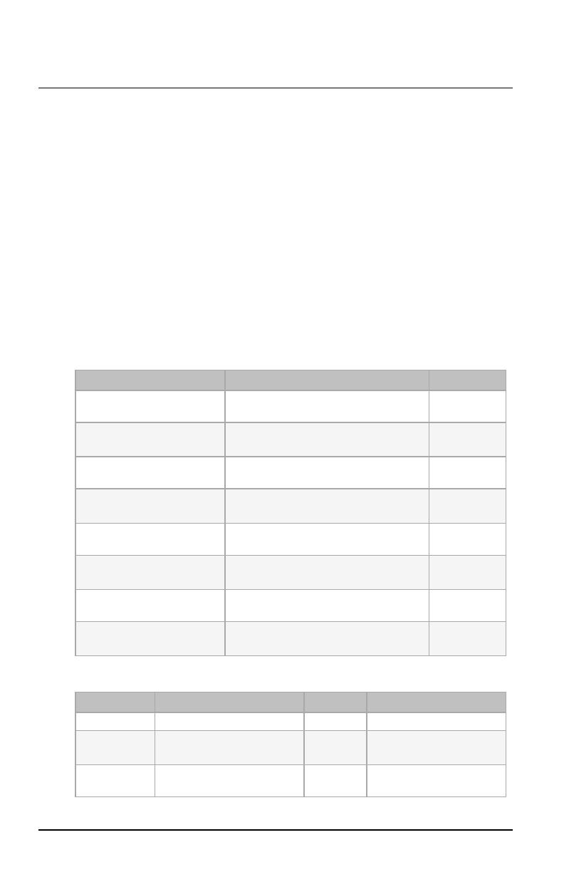
Device Type Power LED LearnLED
Switches 1 long blink followed by short blinks
that count the switches Off
Occupancy sensors 2 long blinks followed by short blinks
that count the sensors Off
Photo sensor
(maximum of 1)
3 long blinks followed by short blink
that counts the sensor Off
Gateways and TimeClocks 4 long blinks followed by short blinks
that count the devices Off
Demand response 5 long blinks followed by short blinks
that count the devices Off
Entry door sensors 6 long blinks followed by short blinks
that count the sensors Off
Window sensors 7 long blinks followed by short blinks
that count the sensors Off
Keycard switches 8 long blinks followed by short blinks
that count the switches Off
Linking Activities
Activity Power LED LearnLED Light Response
Linkmode Blinking On solid Cycles ON and OFF
StorelinkID On for 4 seconds, and then
blinking On solid ON for 4 seconds, and
then cycles
ClearlinkID Off for 4 seconds, and
then blinking On solid OFF for 4 seconds, and
then cycles
LED Fixture Controller (240-347VAC) Page 6 of 8 Echoflex


