Autodesk AutoCAD for Macintosh 2017 User guide
- Type
- User guide

1
AutoCAD 2017 for Mac Preview Guide
User Interface ................................................................................................................................................................ 2
Tool Sets ........................................................................................................................................................................ 3
Custom Tool Set Panels ............................................................................................................................................. 7
Toolbar ........................................................................................................................................................................... 9
File Tabs ....................................................................................................................................................................... 10
Quick View Panel ......................................................................................................................................................... 11
Layout Tabs .................................................................................................................................................................. 11
Status Bar ..................................................................................................................................................................... 12
Properties Window ...................................................................................................................................................... 13
Layers Palette .............................................................................................................................................................. 14
Importing PDF Files ...................................................................................................................................................... 14
IMPORT Command .................................................................................................................................................. 15
PDFIMPORT/-PDFIMPORT Command ..................................................................................................................... 17
Publish to PDF .............................................................................................................................................................. 19
Associative Centerlines and Center Marks .................................................................................................................. 21
Text Editor Visor .......................................................................................................................................................... 24
Parametric Menu ......................................................................................................................................................... 25
Multiple AutoCAD Sessions ......................................................................................................................................... 26
Full Screen ................................................................................................................................................................... 27
License Manager .......................................................................................................................................................... 28
Autodesk Account Sign-In ............................................................................................................................................ 29
2D Graphics.................................................................................................................................................................. 30
Delete Key .................................................................................................................................................................... 31
Hatch Layer .................................................................................................................................................................. 32
TEXTEDIT Command .................................................................................................................................................... 32
Rendering .................................................................................................................................................................... 32
Offline Help .................................................................................................................................................................. 32

2
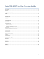
User Interface
Significant changes have been made to the user interface for AutoCAD 2017 for Mac.
The tool sets have been redesigned for better organization and to provide access to more tools.
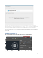
A toolbar has been added above the drawing window containing frequently used commands
such as New Drawing, Save, Open, Undo, Redo, and Print.
File tabs provide an easy way for you to access all the open drawings in the application.
Layout and model tabs are now available in the lower-left corner under the drawing area, to
easily switch between the Model and the existing layouts.
The Status Bar has been updated and is now in line with the Model and Layout tabs.
The layer tools have been added to the Properties window for easy access and the Properties
window is part of the application frame.
The Layers palette contains more layer properties.
The command line is anchored at the bottom of the drawing area.

3
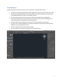
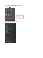
Tool Sets
The tool sets are divided into two tabs: Drafting and Modeling.
Note: AutoCAD LT does not contain the Modeling tab.

4
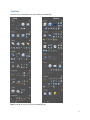
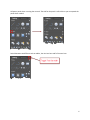
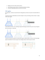
Each tab contains predefined standard panels, grouping related commands together. Click on any
standard panel to select which commands to show or hide from that set.

5
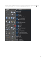
You can change the order of the panels on a tool set.
Drag the panel titles to define the order.

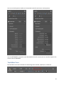
6
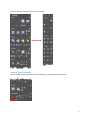
Collapse a panel when not using the controls. The title for the panel is still visible so you can expand the
panel when needed.
Switch between two different tool set widths, the mini tool sets and full size tool sets.

7
The mini tool sets use small icons for all commands.
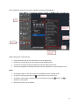
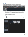
Custom Tool Set Panels
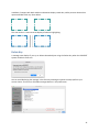
You can create custom tool panels. Click the plus sign (+) at the bottom of the tool set.

8
Enter a panel title, select the icon layout, and add commands and dropdowns.
While creating your custom tool set:
Drag commands from the full command list to the preview panel.
Hover over a command to see the command name and description.
Use Shift or Command to select multiple commands to add to the tool set.
Easily add a dropdown and drag commands under the dropdown to create a subset of icons.
Notes:
All changes happen in real time so you can immediately see the changes made.
To edit your custom panel later, click on the panel to return to this view.
To delete a custom panel, move the mouse over the panel to see the button. Click to
delete the custom panel.
Standard tool sets can’t be deleted.

9
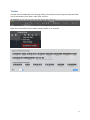
Toolbar
A toolbar has been added above the drawing window. This toolbar contains frequently used commands
such as New Drawing, Save, Open, Undo, Redo, and Print.
Right-click on the toolbar to show labels, hide the toolbar, or to customize.

10
File Tabs
File tabs provide an easy way for you to access all the open drawings in the application.
Clicking the plus sign (+) on the file tabs bar opens a new drawing. If a default template isn’t
specified in Preferences, you can select a template. That template is used as the default from
that point on.
Use Control+TAB to navigate through the file tabs.
Right-click on the file tabs to access the shortcut menus that have options to open, close, or
save drawings.
Click to open the Quick View where you can preview and switch between open drawings
and layouts in an open drawing.

11
Quick View Panel
You can now select and delete multiple layouts on the Quick View panel.
Layout Tabs
Use the layout tabs, located in the lower-left corner under the drawing area, to easily switch between
the model and the existing layouts.
Click to create a layout.
Drag any layout tab to change the order listed.
Right-click a layout tab to rename, delete, or copy.
Press command+] to switch to the next tab or command +[ to switch to the previous tab.

12
Status Bar
The Status Bar has been updated and is now in line with the Model and Layout tabs. Command+6
toggles the display of the Status Bar along with the Model and Layout tabs.
Click to display or hide commands on the Status Bar.

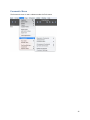
13
Properties Window
The Properties window is now part of the application frame. It can be turned off or on and you can
change the width. Layer controls are added to the top of the Properties window for easy access.

14
Layers Palette
If you need to see more layer properties than what are included on the Properties window, you can
open the Layers palette by any of these methods:
Click the button in the upper right of the Properties window.
Press Command+4
Select Window menu > Layers.
More properties are now included on the Layers palette.
Importing PDF Files
PDF files are a common way of publishing and sharing design data for review and markup. AutoCAD
currently supports creating PDF files as a publishing output for AutoCAD drawings. PDF files can be
attached to drawings, which can be used as a reference when collaborating on projects. In AutoCAD
2017 for Mac, you can import the geometry, TrueType text, and raster images from a specified page in a
PDF file, or from all or part of an attached PDF underlay.

15
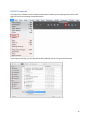
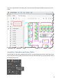
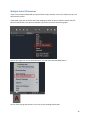
IMPORT Command
The Import tool, available from the Toolbar and File Menu, enables you to import geometry from a PDF
page into the current drawing as AutoCAD objects.
In the Import File dialog, you see that PDF has been added to the list of supported file formats.

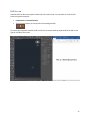
16
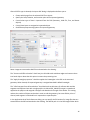
After a PDF file type is selected, the Import PDF dialog is displayed and allows you to:
Choose which page from the selected PDF file to import
Specify the Scale, Rotation, and Insertion point of the imported geometry
Control what type of data is imported from the PDF (Geometry, Solid fills, Text, and Raster
objects)
Control how layers are assigned to imported objects
Set different postprocessing options for imported geometry
Raster images are extracted as PNG files and attached to the drawing.
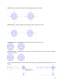
The “Convert solid fills to hatches” check box joins 2D solids with coincident edges and converts them
into hatch objects. Note that this option increases the processing time.
The “Apply lineweight properties” check box applies the lineweights in the PDF to the extracted
geometry. When cleared, all imported geometry is assigned AutoCAD’s default lineweight.
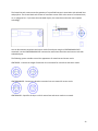
The “Infer linetypes from collinear dashes” check box looks at collections of collinear dash and dot
segments and replaces them with a single polyline. A dashed PDF_IMPORT linetype is created and
applied to the polyline and assigned a linetype scale based on the length of the dashes. This setting
reduces the number of objects and makes it easier to edit the geometry, but some fidelity is lost. If
cleared, each segment in a dashed line is imported as a separate pline.
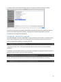
In the Application tab of the Preferences dialog, you can specify the file location for image files that are
extracted from the PDF and attached to the drawing. The default path is in the PDF Images folder which

17
is relative to the location of PDF file being imported. The path can be either absolute or relative.
The PDF file format doesn’t recognize SHX text. When drawings with SHX fonts are plotted to PDF, the
PDF stores that data as geometry (not text), so the SHX text is imported as geometry. Text with
TrueType fonts are imported as text objects.
PDFIMPORT/-PDFIMPORT Command
The new PDFIMPORT command (–PDFIMPORT if using command line access) offers an alternate way for
you to import PDF geometry into the current drawing. The initial options provide a choice either to
select an attached PDF underlay, or to specify a PDF file.
If you choose the File option, the Import PDF dialog is displayed just as when you use the IMPORT
command.
If you select an attached PDF underlay, you can specify a rectangular or polygonal boundary around the
objects you want to import, or you can import everything.
You can also choose to keep, detach, or unload the PDF underlay after the objects are imported.

18
The Settings option in the PDFIMPORT command displays a dialog that provides the same settings as
those in the Import PDF dialog.
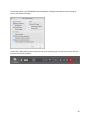
If you select a PDF underlay that is attached to the current drawing, you can access the Import PDF tool
from the visor of PDF Underlay.

19
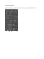
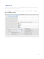
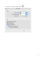
Publish to PDF
Buttons are now available to add the current drawing and remove the model space sheet from the list
for publishing. The dialog is also now resizable.
Publishing is updated with PDF.pc3 support. You can now pick one of the five predefined PDF presets
when plotting your drawings to PDF. These presets provide a way to quickly set different PDF output
options that fit various purposes.

20
Click PDF Options to modify the individual settings.
Page is loading ...
Page is loading ...
Page is loading ...
Page is loading ...
Page is loading ...
Page is loading ...
Page is loading ...
Page is loading ...
Page is loading ...
Page is loading ...
Page is loading ...
Page is loading ...
-
 1
1
-
 2
2
-
 3
3
-
 4
4
-
 5
5
-
 6
6
-
 7
7
-
 8
8
-
 9
9
-
 10
10
-
 11
11
-
 12
12
-
 13
13
-
 14
14
-
 15
15
-
 16
16
-
 17
17
-
 18
18
-
 19
19
-
 20
20
-
 21
21
-
 22
22
-
 23
23
-
 24
24
-
 25
25
-
 26
26
-
 27
27
-
 28
28
-
 29
29
-
 30
30
-
 31
31
-
 32
32


Autodesk AutoCAD for Macintosh 2017 User guide
- Type
- User guide
Ask a question and I''ll find the answer in the document
Finding information in a document is now easier with AI
Related papers
-
Autodesk Autocad 2017 User guide
-
Autodesk AutoCAD LT 2012 Operating instructions
-
-
-
-
-
-
-
-
Other documents
-
Corel CorelCAD 2017 User guide
-
-
-
-
 Wiley 978-0-470-10993-9 Datasheet
-
Aviom A360 User guide
-
-
Corel CorelCAD 2014, Win/Mac, EDU, ML User guide
-
Aviom A360 Display User guide
-
