2
49-80152-7
Safety Information
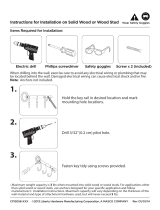
BEFORE YOU BEGIN
Read these instructions completely and carefully.
•
IMPORTANT³Save these instructions for
local inspector’s use.
•
IMPORTANT³Observe all governing codes
and ordinances.
• Note to Installer³ Be sure to leave these
instructions with the Consumer.
• Note to Consumer³ Keep these instructions
with your Owner’s Manual for future reference.
• Skill Level³Installation of this appliance requires
basic mechanical and electrical skills.
• Completion Time³WR+RXUV
• Proper installation is the responsibility of the installer.
Product failure due to improper installation is not
covered under the warranty.
)RU0RQRJUDPORFDOVHUYLFHLQ\RXUDUHDFDOO
)RU0RQRJUDPVHUYLFHLQ&DQDGDFDOO
)RU0RQRJUDP3DUWVDQG$FFHVVRULHVFDOO
CAUTION:
Due to the weight and size of these vent hoods and
to reduce the risk of personal injury or damage to the
product, TWO PEOPLE ARE REQUIRED FOR PROPER
INSTALLATION.
WARNING:
To reduce the risk of fire or electrical shock, do not
use this range hood with any external solid-state speed
control device. Any such alteration from original factory
wiring could result in damage to the unit and/or create
an electrical safety hazard.
TO REDUCE THE RISK OF FIRE, USE ONLY METAL DUCTWORK.
WARNING: TO REDUCE THE RISK OF
FIRE, ELECTRICAL SHOCK OR INJURY TO PERSONS,
OBSERVE THE FOLLOWING:
A. Use this unit only in the manner intended
by the manufacturer. If you have any questions, con-
tact the manufacturer.
B. Before servicing or cleaning the unit, switch
the power off at the service panel and lock the service
disconnecting means to prevent the power from
being switched on accidentally. When the service dis-
connecting means cannot be locked, securely fasten
a prominent warning device,
such as a tag, to the service panel.
CAUTION: FOR GENERAL VENTILATING
USE ONLY. DO NOT USE TO EXHAUST HAZARDOUS
MATERIALS, EXPLOSIVE MATERIALS OR VAPORS.
WARNING: TO REDUCE THE RISK OF
FIRE, ELECTRICAL SHOCK OR INJURY TO PERSONS,
OBSERVE THE FOLLOWING:
• Installation work and electrical wiring must be done
by qualified person(s) in accordance with all applicable
codes and standards, including fire-rated construction.
• Sufficient air is needed for proper combustion
and exhausting of gases through the flue (chimney)
of fuel burning equipment to prevent back-drafting.
Follow the heating equipment manufacturer’s guide-
lines and safety standards, such as those published
by the National Fire Protection Association (NFPA), the
American Society for Heating, Refrigeration and Air
Conditioning Engineers (ASHRAE) and the local code
authorities. When applicable, install any makeup
(replacement) air system in accordance with local
building code requirements.
Visit GEAppliances.com
for available makeup air solutions.
• When cutting or drilling into walls or ceilings, do not
damage electrical wiring and other hidden utilities.
• Ducted systems must always be vented
to the outdoors.
• Local codes vary. Installation of electrical connections
and grounding must comply with applicable codes.
In the absence of local codes, the vent should be
installed in accordance with National Electrical Code
ANSI/NFPA 70-1990 or latest edition.
CAUTION: To reduce risk of fire and to
SURSHUO\H[KDXVWDLUEHVXUHWRGXFWDLURXWVLGH³do not
vent exhaust air into spaces within walls or ceilings or
into attics, crawl spaces or garages.
READ AND SAVE THESE INSTRUCTIONS