Page is loading ...

ZV48RSFSSMONOGRAM 48" STAINLESS STEEL PROFESSIONAL HOOD
Listed by
Underwriters
Laboratories
Product Specification Revised 1/18
Model ZV48R
47-15/16"
47-15/16"
25"
12"
22-1/2"
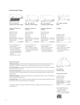
Each hood is shipped with a stainless steel backguard
and a warming shelf. Hoods may be installed with the
shelf or backguard alone, or with both as shown.
Warming
Shelf
Backguard
Install these hoods 30" Min. to
36" Max. over a professional
style cooktop or range.
Allow 32" Min. and 38" Max.
clearance above any cooking
surface when installed with shelf.
In this installation the ductwork running from the top of the
hood will be concealed in the sot or upper cabinetry.
Install these hoods 30" Min. to
36" Max. over a professional
style cooktop or range.
Allow 32" Min. and 38" Max.
clearance above any cooking
surface when installed with shelf.
For this installation, a decorative duct cover is available to
conceal the ductwork running from the top of the hood. Use of
the duct cover requires special consideration to the installation
height above the countertop.
DIMENSIONS AND INSTALLATION INFORMATION
(IN INCHES)
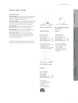
INSTALLATION CLEARANCES
These vent hoods are designed to be installed onto a
wall or beneath a sot or cabinet.
INSTALLATION WITH WARMING SHELF
• Hoods must be installed 32" Min., 38" Max. over any
type cooking surface when warming shelf is used
INSTALLATION WITHOUT WARMING SHELF
• Install these hoods 30" Min. to 36" Max. above the
cooking surface when installed over any professional
style cooktop or range.
*These hoods may be installed 24" min. above a gas or electric
drop-in style cooktop.
NOTE
Clearances may vary due to type of cooking product
and local codes. Check with local inspectors to be sure
standard is applicable.
SOFFIT INSTALLATION WALL MOUNT INSTALLATION
SOFFIT
SOFFIT
32" min.
38" max.
30" min.
36" max.
SOFFIT
SOFFIT
32" min.
38" max.
30" min.
36" max.

ZV48RSFSSMONOGRAM 48" STAINLESS STEEL PROFESSIONAL HOOD
Listed by
Underwriters
Laboratories
Product Specification Revised 1/18
POWER SUPPLY
IMPORTANT – (PLEASE READ CAREFULLY)
WARNING
FOR PERSONAL SAFETY, THIS APPLIANCE MUST BE
PROPERLY GROUNDED.
Remove house fuse or open circuit breaker before
beginning installation.
Do not use an extension cord or adapter plug with this
appliance. Follow national electrical codes or prevailing
local codes and ordinances.
ELECTRIC SUPPLY
These vent hoods must be supplied with 120V, 60Hz, and
connected to an individual, properly grounded branch
circuit, and protected by a 15 or 20 amp circuit breaker or
time delay fuse.
• Wiring must be 2 wire with ground.
• If the electrical supply does not meet the above
requirements, call a licensed electrician before proceeding.
• Route house wiring as close to the installation location as
possible on the back wall or ceiling.
• Connect the wiring to the house wiring in accordance with
local codes.
GROUNDING INSTRUCTIONS
The grounding conductor must be connected to a ground
metal, permanent wiring system, or an equipment-grounded
terminal or lead on the hood.
WARNING
The improper connection of the equipment-grounding
conductor can result in a risk of electric shock. Check with
a qualified electrician or service representative if you are in
doubt whether the appliance is properly grounded.
OPTIONAL DUCT COVER ACCESSORIES
Decorative duct covers are available in 6" and 12" heights.
Duct covers may be stacked, in various combinations, to
conceal the ductwork running from the top of the hood
to the ceiling.
• Before you begin, you should
determine the installation
height of the hood and order
the correct size duct cover. The
duct covers should be ordered
at the same time as the vent
hood and be on site before
installation. Order the duct cover
corresponding to your model.
6" DUCT COVERS
HOOD MODEL 6" DUCT COVER DIMENSIONS
ZV48R ZX48DC6 6"H x 19-11/16"W x
11-7/8"D
12" DUCT COVERS
HOOD MODEL 12" DUCT COVER DIMENSIONS
ZV48R ZX48D12 12"H x 19-11/16"W x
11-7/8"D
ADVANCED PLANNING
DUCTWORK PLANNING
• These vent hoods are equipped for 10" round ductwork.
In most instances they may be transitioned to 8" round.
• This hood may be vented vertically through upper
cabinets, sot or ceiling. A duct transition piece is
supplied for vertical exhaust. Use locally supplied elbows
to vent horizontally through the rear wall.
• Determine the exact location of the vent hood.
• Plan the route for venting exhaust to the outdoors.
• Use the shortest and straightest duct route possible.
For satisfactory performance, duct run should not exceed
150 ft. equivalent length for any duct configurations.
• Refer to “Duct Fittings” chart to compute the maximum
permissible length for duct runs to the outdoors.
• Use metal ductwork only.
• Install a wall cap or roof cap with damper at the exterior
opening. Order the wall or roof cap and any transition
needed in advance.
WALL FRAMING FOR ADEQUATE SUPPORT
• These vent hoods are heavy. Adequate structural support
must be provided. Hoods must be secured to vertical
studs in the wall.
• It is strongly recommended that the vent hood with duct
cover be on site before final framing and wall finishing.
This will also help to accurately locate the ductwork and
electrical service.
DECORATIVE DUCT COVERS
Decorative duct covers, 6" and 12" high, are available to fit
all models. The duct cover conceals the ductwork running
from the top of the hood to the ceiling or sot. Stack one
or more duct covers over the top of the hood to reach
your ceiling height.
6" Duct Cover
12" Duct Cover

ZV48RSFSSMONOGRAM 48" STAINLESS STEEL PROFESSIONAL HOOD
Listed by
Underwriters
Laboratories
Product Specification Revised 1/18
A - B = C
Ceiling Height
A
C
B
10" Hood
Height
INSTALLATION EXAMPLES
32"
12"
38"
24"
32"
42"
INSTALLATION EXAMPLES
32"
12"
38"
24"
32"
42"
INSTALLATION EXAMPLES
32"
12"
38"
24"
32"
42"
USING DUCT COVER ACCESSORIES
To avoid unsightly gaps, plan the hood installation
height for duct covers use. Use the following formula to
calculate the need for one of more duct covers and to
ensure a trouble free installation.
We recommend that the vent hood and decorative
duct cover (if used) be on site before final framing and
wall finishing. This will help to accurately locate studs,
ductwork and electrical service.
• Read these examples carefully to determine the need
for one or more 6" or 12" duct covers.
A = Countertop to ceiling height.
B = Gap at the top of the hood to the ceiling.
C = Hood installation height – Plus 10" hood height.
NOTE
Dia. C should be between 40" and 46" (for a 30" to 36"
installation height). Raise or lower the hood installation
height to allow use of one or more 6" and 12" duct covers.
CEILING HEIGHT
10 FT. CEILINGS
When the hood is
installed 36" above
the cooking surface,
order three 12" and
one 6" duct cover
accessories.
9 FT. CEILINGS
When the hood is
installed 38" above
the cooking surface,
order two 12" duct
cover accessories.
8 FT. CEILINGS
When the hood is
installed 32" above
the cooking surface
and there is no
sot or upper
cabinetry, order one
12" and one 6" duct
cover accessory.
INSTALLATION EXAMPLES

ZV48RSFSSMONOGRAM 48" STAINLESS STEEL PROFESSIONAL HOOD
Product Specification Revised 1/18
1090 CFM VERTICAL EXHAUST
WITH DUAL BLOWERS
3 HALOGEN LAMPS WITH 4 LIGHTING LEVELS
INFRARED WARMING LAMP
UTENSIL RACKS
REMOVABLE GREASE TRAYS
DISHWASHER-SAFE REMOVABLE
STAINLESS STEEL FILTERS
VARIABLE SPEED FAN CONTROL
FEATURES AND BENEFITS
/