Page is loading ...


- 2 -
Table of Contents
Chapter 1: Introduction 5
Overview 5
Main Features of the LE/LE-HC Series 5
Chapter 2: Getting Started 7
General Description 7
First time starting the LE/LE-HC Series DVR 7
Configuration and operation via the Infrared Remote (IR) Control 7
LE/LE-HC Series Networking 7
Chapter 3: LE/LE-HC/HC Series Network Operations 8
Default Configuration 8
Network Installation 8
Testing the Network Connection 8
Chapter 4: Configuring the LE/LE-HC Series DVR 10
First Connection to LE/LE-HC Series DVR 10
Configuration of LE/LE-HC Series DVR 10
Advance Setting 11
a) System Information 11
b) Camera Settings 11
c) Audio Setting 12
d) Set Date & Time 13
e) Set NTP Server 13
f) System Configuration 13
g) Serial Ports 15
h) Set User’s Authority 16
i) DVR Setup 16
j) Record Schedule 16
k) Motion Detection 17
l) Set Pre-Alarm 17
m) Playback and search 18
n) Send Mail 19
o) FTP Upload 20
p) View Video without Plugins 20
Chapter 5: Configuring DVR using Remote Control 21
Configure LE/LE-HC Series for a network with Remote Control 21
Using the Menus 21
a) Use the Menus 21
b) Operating the Menus and
Changing the setting Parameters 22
c) View the Previous/Next Page 22
d) Exit the Menus 22
e) Video Recording Setup 22
System Setup (Configuration) in IR Mode 23
a) Password Protect 23
b) Video 23

- 3 -
c) Video Input 25
d) Disks 26
e) TV Output 26
f) OSD Text 26
g) TCP/IP Settings 26
h) Account Settings 27
i) Audio 27
j) Serial Ports 27
k) System Information 28
l) Date/Time 30
m) Alarm 29
n) ISP 29
o) Registry Server Setting 29
p) Running Mode 29
q) Algorithm Setting 30
r) NTP Setup 30
Configure recording in IR Mode 31
Motion Detection 32
Playback with IR Controller 33
System Shutdown 35
Chapter 6: Configuring LE/LE-HC Series DVR using GUI mode 36
Playback (Viewing recorded events) 40
System Setup (Configuration) 45
a) System Setup 45
b) Record Setup 56
c) Motion Detection 59
Chapter 7: Using PTZ Cameras in IR Mode 61
Appendix A 62
Appendix B 64


LE/LE-HC Series DVR User Manual
V1.4 October 2006
- 5 -
Chapter 1: Introduction
Overview
Thank you for purchasing the LE/LE-HC Series Digital Video Recorder. This product is ideal for all
of today’s video security needs. From home users to industrial applications, the LE/LE-HC Series
DVRs can do it all – simply, completely and reliably. This high performance DVR has a built-in
dedicated web server, and record and display capability. Video is compressed using one of
several user selectable compression algorithms called codecs (compressor/decompressor). The
system will record this data onto a hard drive, overwriting the oldest recordings first, when the disk
is full. Video is displayed on a SVGA Monitor. The base system has four cameras, which can be
upgraded to a total of sixteen cameras (depending on the model purchased) with no loss of frame
rate.
This DVR is unique in that the software is contained (embedded) in a firmware module called a
DOM, which allows a fresh “re-install” every time the system is turned on. No need to worry about
the traditional problems of viruses, Trojans, software glitches or other Windows™ based issues as
the install is completely fresh every time. A small area of the module contains the user configured
data. No software is contained on the hard drive, so software cannot be corrupted.
Adding additional cameras to the system is as simple as turning off the DVR, plugging in another
four camera connector card, and turning it back on. Configuration is done in GUI mode with a
mouse, by the included remote controller in full screen mode or through a remote PC. This remote
PC control allows users to switch cameras, control any PTZ cameras installed, and change all the
features of the DVR, with the appropriate password authority.
The DVR is accessible through the Internet, or a local Intranet, with some simple configuration
modifications to the DVR. Through a registry server the LE/LE-HC Series DVR supports Dynamic
IP addresses.
The remote software is all browser based and accessible using any reasonably current version of
Windows™ Explorer. Linux, Mac and some PDAs are supported through additional (included)
software.
Main Features of the LE/LE-HC Series
Ease of use
Plug and play, non-Windows™ embedded real-time OS
Simple configuration via keyboard/mouse, IR Controller or Internet/LAN
Uses a standard web browser for remote PC access.
Video & audio recording
Up to 16 camera inputs (color or B/W) are supported in multiples of four.
Adding cameras is accomplished by installation of additional cards.
Up to 30 fps is provided on each camera for local monitoring
Record / display / playback/ remote access simultaneously
Built-in Multiplexing with local monitoring
Local playback of recorded video on VGA monitor
Remote playback of recorded video using standard PC browser

LE/LE-HC Series DVR User Manual
V1.4 October 2006
- 6 -
Search recorded data by date, time & events
Control multiple brands of PTZ Cameras
High video quality and low data rate
Up to 200:1 video compression
Multiple video compression engines:
LE: MPEG4, H.263, JPEG, M-JPEG
LE-HC: MPEG4
Networking is supported and allows remote access
Dynamic IP support for Internet access
Direct Dial-up available with optional external modem
Backup
CD or DVD writer
Alarm function
Motion detection / Event trigger / Schedule / Pre-alarm recording
E-Mail, FTP and Voice Call alarm notification
Optional GPI/O for alarm control
Customization
Supports HTML file upload for home page customization

LE/LE-HC Series DVR User Manual
V1.4 October 2006
- 7 -
Chapter 2: Getting Started
General Description
Configuring the LE/LE-HC Series DVR can be accomplished in several ways. The Infrared
Remote Control included with the LE/LE-HC Series DVR works in IR Mode when the receiver is
connected to a USB port on the back of the LE/LE-HC Series DVR. Alternatively, in GUI Mode
(Graphic User Interface) a mouse and keyboard can be used. If configured for LAN or Internet, a
web browser can be used to configure the DVR.
We have found the easiest way to configure the system is to use the Infrared Remote Control to
configure the IP settings, then once on the net use the remote configuration from an alternate PC.
First time starting the LE/LE-HC Series DVR
Before turning the DVR on, connect the appropriate video inputs, monitor and network adapter to
the back of the DVR. The system will automatically detect the video mode (NTSC or PAL) of the
cameras connected (default is NTSC if no cameras are connected). Symptoms of incorrect video
configuration are B/W video when color is expected or the top or bottom of the video cut off.
The LE/LE-HC Series records automatically on power up. The Default IP address is
192.168.10.10, which is within the range of most Intranets. The Sub-net mask is preset to
255.255.255.0, also within the range of most intranets.
Configuration and operation via the Infrared Remote (IR) Control
Chapter 5: Details the operation of the IR Control.
LE/LE-HC Series Networking
Chapter 3: Details the operation of the Networking Operations.

LE/LE-HC Series DVR User Manual
V1.4 October 2006
- 8 -
Chapter 3: LE/LE-HC Series Network Operations
Default Configuration
The LE/LE-HC Series DVR comes preconfigured. A list of the default settings is included in
Appendix A of this document.
Network Installation
The LE/LE-HC Series DVR comes preconfigured as a static IP. TCP/IP networks either have the
IPs assigned manually, or by a DHCP (Dynamic Host Configuration Protocol) Server. Most
Internet routers and Windows 2000 Server™ use DHCP to assign IP addresses. The reason for
assigning a static IP within this environment is that when a leased IP from a DHCP server runs out
(which can happen every day), the LE/LE-HC Series DVR may not re-acquire the old IP address.
This will break functionality within the Intranet or LAN environment and will break any port
forwarding assigned within the router that allows external (internet) users to connect to the LE/LE-
HC Series DVR.
Most networks using a router or a Windows 2000 Server © should be able to see the LE/LE-HC
Series DVR once it is connected.
In the case the IP address pre-assigned to the LE/LE-HC Series DVR (192.168.10.10) may
already be assigned to another networking device; finding another machine on the network and
attempting to ping that IP address will tell if there is a unit already connecting on that specific IP (if
it says no IP found, it’s a good indication that there is no unit connected at that IP). Use the ping
method in figure 3.1 but instead of times<1ms or similar (up to 200ms), look for Request Timed
Out. This indicates that there is no computer currently on the network at that location. Failure to
check this could cause the LE/LE-HC Series DVR to push another machine off the network or
cause other problems.
In cases where this machine is connected directly to a DSL modem or Cable Modem, these steps
may be ignored; however, additional configuration is usually required.
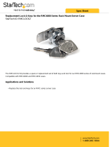
Testing the Network Connection
From any computer on the network, click on the
start button and click on run (Windows 98, ME,
2000, XP). Type in command and click OK. This
will bring up a DOS prompt. Type in PING
192.168.10.10. A good connection will look like
Figure 3.1
If the ping fails, check all the wires to make sure
there are connected. Look at the back of the DVR
and on the device to which the other end of the
cable is connected (a switch, router or hub most
likely). Make sure that the connection lights are
on, on both ends. Unplugging and reconnecting cables can fix many problems. Rebooting the
Figure 3.1

LE/LE-HC Series DVR User Manual
V1.4 October 2006
- 9 -
DVR is required if the light is off, and pushing the connector turns the light on. These lights will
usually be located right next to the connector plug on the DVR, and there are usually a bank of
lights on the router that show valid connections. If in doubt, unplug the cable and see if one of the
lights goes out.
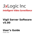
Once a physical connection has
been established, the next thing
to check is the network settings.
The first step is to bring up a
DOS prompt. From any
computer on the network, click on
the start button and click on run.
(Windows™ 2000, XP). Type in
“command” and click OK. This
will bring up a DOS prompt.
Type in “ipconfig /all”, and press
enter. If all goes well, Figure 3.2.
The information needed is the
subnet mask, default gateway,
and DNS Servers. Note the IP
addresses. The number after the last “dot”, e.g. in 192.168.0.20, the number 20 is the one to
change for the DVR. Picking a number above 200 (max is 254) should be OK, unless the unit is
being installed in a large networking environment. In that case, they will have a network
administrator who knows the exact settings required.
The LE/LE-HC Series can be assigned a dynamic IP by a DHCP Server (usually a router or
Windows 2000 Server) by assigning the DVR IP address 255.255.255.253. This does give the
added complication of finding out what IP was assigned, and while there is software that can
locate the LE/LE-HC Series DVR on the network, it is easier to assign a static IP.
Figure 3.2

LE/LE-HC Series DVR User Manual
V1.4 October 2006
- 10 -
Chapter 4: Using and Configuring the LE/LE-HC Series DVR
Remotely
First Connection to LE/LE-HC Series DVR
Once the LE/LE-HC Series DVR is installed on the network, use
another Windows© based machine on the network and try to
connect to the LE/LE-HC Series DVR -accomplished by opening
up a browser and entering in the address bar http://192.168.10.10
(or the configured IP address for the LE/LE-HC Series DVR)
A window should pop up looking like figure 4.1. Note that the IP
may differ depending on what was configured. The default
Administrator name is “admin” and the password is
“sentry”. This will allow remote access to the LE/LE-HC
Series DVR.
To view live video from a LE/LE-HC Series DVR
remotely, a Live Video Active X Component is required.
If the Active X Component has never been installed, or a
previous version is on the remote machine, a window will
pop up which requests downloading LVSETUP.EXE (see
figure 4.2).
Configuration of LE/LE-HC Series DVR
When connecting to The LE/LE-HC Series DVR from a remote PC, the web browser display will
be Figure 4.3.
Figure 4.3
Figure 4.1
Figure 4.2
Playback recorded files
System Setup
The Surveillance Screen Panel
enables the definition of the number
of camera images displayed on
screen.

LE/LE-HC Series DVR User Manual
V1.4 October 2006
- 11 -
Similar local configuration options are available with the GUI and IR interface, although the easiest
method for configuration is the remote configuration.
Advance Setting
After the initial login, typing in the URL in Section 3.4 will bring up the page in
Figure 4.4. Clicking on the
(System Setup) button will display the
screen which is partially shown in Figure 4.5 (Clicking on System Setup will
bring up a login prompt if the original Password and User ID do not have
sufficient privilege).
Making changes to the settings will often cause the LE/LE-HC Series DVR to
reboot when the done button is clicked. This is unavoidable, and video will
not be recorded while the DVR is rebooting. This process can take 3 to 4
minutes.
Each of the items in the list in Figure 4.4 are
covered in the following subsections of Section
4.3
a) System Information
This page gives information about the LE/LE-HC
Series DVR. Most of this information isn’t
required on a day to day basis, but may be
required by a network administrator or
Technician should the occasion arise.
b) Camera Settings
1. Video Source: Select camera to display
2. Brightness, Contrast, Saturation, Hue and
Quality: Change Brightness, Contrast,
Saturation, Hue and Quality here. These
parameters are applied to all cameras. To adjust
brightness of each individual camera, please use
“Gain Control” as described in Item 5.
3. Compression Boost: Selection can be “None”,
“Low”, “Medium” and “High” to adjust video
compression rate. The higher the “Compression
Boost” level, the smaller the compressed frames
become providing faster remote transmissions
and smaller recorded files but poorer video
quality.
Figure 4.4
Fi
g
ure 4.5

LE/LE-HC Series DVR User Manual
V1.4 October 2006
- 12 -
4. Video Resolution: Selection can be either 320x240 or 640x480. A higher resolution will provide
better video quality but will use more hard drive space and bandwidth.
5. Auto Gain Control: When this box is checked, the LE/LE-HC Series will keep the GAIN value
effective automatically no matter day or night, light or dark.
6. Mirror Horizontally: Self Explanatory
7. Mirror Vertically: Self Explanatory
8. Watermark: Inserts watermark into picture.
Set Camera Control (PTZ camera configuration settings)
1. Camera Control Device: Use the drop-down menu to select the correct PTZ protocol.
2. Baud Rate(bps): Select the correct PTZ camera baud rate.
3. PTZ ID: Enter the PTZ ID (set directly on the camera)
4. Timeout (sec): Select desired timeout; default is 120 seconds
Other Settings
1. Max connections for this camera: Limit the maximum number of concurrent (remote)
connections to this camera.
2. Max bandwidth for this camera (Bytes/sec): Limit the maximum bandwidth in Bytes/second
allocated to this camera.
3. Max bandwidth of each connection for this camera (Bytes/sec): Limit the maximum bandwidth
allocated to each connection of this camera.
Click the “Done” button to save any settings changes.
Note: Please click “Write To FlashROM!” to save data
c) Audio Setting
Users accessing this for the first time will be required
to download LASETUP.EXE if they have not listened
to audio previously.
1. Audio Source. Select the source to modify.
Figure 4.7
Figure 4.6

LE/LE-HC Series DVR User Manual
V1.4 October 2006
- 13 -
2. Microphone Gain: Similar to video gain, it amplifies the signal before audio is processed
3. Audio Selection; Choose which camera to associate audio with. * LE-HC has one channel of
audio per video.
3. Speaker Volume: Controls the volume of the speaker
4. Microphone Control Timeout and Speaker Control Timeout determine the length of time that
one remote user can have control of the microphone and speaker.
Currently the LE Series supports a single channel of audio recording.
d) Set Date & Time
Follow the formats when setting the time and date.
e) Set NTP Server
NTP stands for Network Time Protocol. It is a protocol to request
the current time from a time server. Connection to the internet is
required. Check the enable box to turn the Network Time
Protocol service on or off. Set the period to however many
hours, and once per that period, the time will be updated.
Once every 24 hours should be sufficient, if required at all.
Keep in mind that this is a service offered by educational and
government institutions and abuse will result in our loosing
these public time servers. This feature is not generally
required, but a neat feature none the less.
f) System Configuration
This section is broken down into several parts, as this page is
longer than one screen capture will permit. Each of the
configuration options are outlined below:
ISP mode is used when the DVR is connected directly to
a telephone modem. This mode is generally too slow to
see any sort of reasonable data throughput and should
be avoided if at all possible. Configuring ISP mode is
completed in the “ISP Setting” dialog box at the bottom
of Figure 4.10. Phone number, user ID, and password
as well at maximum baud rate should all be entered. If
the ISP assigns an IP address, then configure that in the
TCP/IP settings and check the “Use assigned TCP/IP
Settings” check box.
Network Mode is the default setting and in most
circumstances, the LE/LE-HC Series DVR will be
connected to a network of some sorts. It could be
Figure 4.8
Figure 4.9
Figure 4.10

LE/LE-HC Series DVR User Manual
V1.4 October 2006
- 14 -
connected to a cable connection or DSL line. DSL that uses PPPoE would require a router as
PPPoE requires a login procedure, which is not supported by the LE/LE-HC Series DVR.
Network Mode settings are set in “TCP/IP Settings”
. These need to be configured to have the
LE/LE-HC Series DVR communicate over a network or the Internet.
This area really should not need to be changed, once set, as the connection to the network is
functional.
Account Setting
Under account setting there are two levels of users. Privileges for the user are configured in the
“Set User’s Authority” section covered later in this chapter.
Figure 4.11

LE/LE-HC Series DVR User Manual
V1.4 October 2006
- 15 -
Set Video Compression Algorithm & Resolution
Select one of four Compression algorithms. These are MPEG4, H.263, JPEG or Motion-JPEG.
Please refer to the table below for relationship between Compression format, Video quality & Data
rate:
Compression Format Video Quality Data Rate
JPEG Very Good High
M-JPEG Good High (Less than JPEG)
H.263 Average Low
MPEG4 Good Low
*Please Note: The only compression format available on the LE-HC is MPEG4.
The best compression format depends on network connections; both locally and remote.
Remember that a 3 MB DSL connection means 3 MB download, not 3 MB upload. The 3 MB DSL
can be as low as 284K upload or even 128K. This will have an affect on the remote video frame
rate. Observing video produced remotely under different compression algorithms is the best way
to evaluate requirements. The LE Series DVR is set to H.263 compression as a default. This
provides the fastest video transmission speeds, the smallest recorded files and satisfactory video
quality.
When setting video resolution, remember that 640X480 resolution needs 4 times the physical
bandwidth than that required to produce the same frame at 320X240. Once again, look at the
video and see if the speed loss of frames is worth the increase in resolution quality.
“Set IP Registry Host IP Address & Path” is used where static IPs are unavailable or
impractical. Basically, the LE/LE-HC Series DVR sends its current IP to a computer designated as
a registry (usually a commercial service). Remote users can then access that registry and find out
what the current IP is. This is an imprecise service at best, and is prone to failure, due to the
nature of the internet. However, in cases where a static IP is not available, it is still invaluable.
g) Set Serial Ports
Settings for COM1 and COM2 need only be applied in cases where a GPIO, Modem or PTZ,Voice
Call, Data Capture, Control device is connected to the DVR.
Settings for these particular devices will vary by brand. Specific questions regarding this topic
should be directed to the vendor. Please be aware that not all brands (especially PTZ cameras)
are compatible with this DVR.

LE/LE-HC Series DVR User Manual
V1.4 October 2006
- 16 -
Set Names & On Screen Display (Figure 4.12)
The “Set Names of Server and Cameras” option allows
users to change the name of the server and the camera
names.
Use the “Set Overlay Text” to show text on the camera
image. Check the enable box to make it appear on the
screen and set the X and Y parameters (X being horizontal
and Y being vertical) to assign a specific position (default is
upper left hand corner).
Additionally a time stamp can be configured, per camera
with the “Set Time Stamp” and give a format for the date by
selection from the pull-down menu labeled “Timestamp Date
Format.”
h) Set User’s Authority (Figure 4.13)
Setting the User’s Authority allows the administrator to configure users to have specific privileges
defined by login credentials.
Simply enter a user name and password for the user and then configure
the desired privileges for that user.
Below the box is a URL marked Users Listing which gives a list of all the
users on the DVR.
i) DVR Setup
DVR Setup Defines whether the LE/LE-HC Series DVR will record based
on a first-in first-out recording process, oldest video getting deleted to
make room for new video (circular recording) or if it will stop when the drive is full (Auto Stop).
j) Record Schedule
Multiple schedules can be set up to accomplish specific
recording requirements at pre-determined times. This would
allow maximum usage of hard drive capacity, for instance
recording on motion when a store is closed and recording full
time when the store is open. Use the pull-down menu at the top
of the screen in Figure 4.14 to select the schedule to edit.
There can be a maximum of 16 schedules on any one DVR at
any one time.
Schedule 1 is set by default to be on all the time. Unlike most
traditional DVRs the LE/LE-HC Series DVR uses a schedule all
the time. Care must be taken not to overlap schedules. Use
Fi
g
ure 4.12
Fi
g
ure 4.13
Figure 4.14

LE/LE-HC Series DVR User Manual
V1.4 October 2006
- 17 -
the schedule setup section to configure start time and stop time (make both 00:00:00 for the full
day) and then pick the days of the week this is to be effective. Make sure to turn the “Enable” pull
down menu to “Yes” or the schedule will not run.
Use “Stream Video Setup” to indicate if the camera should record using motion detection, full time
or not have it turned on at all.
For the frame rate, in most instances, auto speed should be turned on. This will give the best
frame rate. However, each camera can be set to record between 1 and 30 frames per second but
total frames added up together cannot be higher than the LE/LE-HC Series DVR is capable of
recording.
k) Set Motion Detection
When motion detection recording is selected in
Section 4.3.0 the specifics of motion detection
are configured in this section. Select the video
source (camera). The camera image will show
on the left hand side of the screen as in Figure
4.15. Use the left mouse button to click on
squares to set detection area and use the right
mouse button to clear areas. Hold down the
left or right mouse button and drag to block
areas larger than single squares. Motion will
only be detected in areas that have the Set
Detection squares, marked in red.
l) Set Pre-Alarm
Use the “Set Pre-Alarm” to set the number of frames recorded before an alarm condition exists.
Each camera can be configured separately and be configured differently.
Figure 4.15

LE/LE-HC Series DVR User Manual
V1.4 October 2006
- 18 -
m) Playback and Search
To bring up a list of recorded video on the
LE/LE-HC Series DVR, either click List All or
set a time frame in the from/to folders and then
click query. The files will be listed in the lower
screen area (see Figure 4.16) and clicking on
one will open the play video screen.
If this is the first time attempting to play back
recorded video on a remote machine (and for
each separate unit accessing remotely) users
will be required to download the
RPSETUP.EXE file when they attempt to play
the video. Download and install the file. Close
the window that says “player not found” and
attempt to play the video file again.
Once the ActiveX component is successfully installed, the video display screen should appear as
in Figure 4.17.
Use the “Dimension” pull down button to
configure the size of the video on the display.
The “Display” button will select the number of
cameras displayed on the screen at any one
time, and the “Camera” button will select which
particular subset (less than 16 cameras
selected) is shown. In most cases, for DSL and
cable connections, select high bandwidth. In
times when the bandwidth available is not very
good, select low bandwidth.
Use the “Download and Save” hyperlink, to save
the video on the remote PC.
At the bottom left hand corner there are six buttons and some other options. These are explained
in Figure 4.18 below:
Figure 4.16
Fi
g
ure 4.17

LE/LE-HC Series DVR User Manual
V1.4 October 2006
- 19 -
Save: Save the data file on the local machine.
Snapshot: Clicking this button brings up a list of Cameras. Select the camera from the
list to snapshot, and then click o.k. It will then bring up a Webpage with the
picture in it, which may be saved by right clicking on the image and selecting
“Save Image As”.
Play: Play video.
Step Forward: When the pause button is pressed, “Step Forward” will move each camera
forward one frame.
Stop: Stop video playing.
Data Type: When data is selected, all recorded video will be played. Selecting motion will
only play video that was recorded based on motion. GPI will play video that
was recorded by an alarm trigger
Seek: Allows specific times to be entered and the video will zoom to that time.
Speed: Playback speed
Use the slider bar above this image to move around
within the time selected. Please note that using the
slider bar or the seek option will cause a delay of
several seconds while the video switches.
n) Send Mail
The mail settings configuration page (Figure 4.19) is
used to alert configured email recipients when specific
events occur on the LE/LE-HC Series DVR.
As many Motion Detect Types (Events) as cameras can trigger an email and an be set for each
camera over a specific time range. Each event must be enabled to send emails. Enable them by
using the pull down menu “Enable” and select enable. Enter appropriate data into the From, To,
Figure 4.18
Figure 4.19
/