Page is loading ...

pg. 1
© 2013 Episode
®
ECS-650-IC Owner’s Manual
WELCOME TO EPISODE
®
Thank you for purchasing a great product from
Episode®, one of the best sounding speaker lines
available today. We appreciate your purchase
and are committed to providing the highest quality
products possible.
The ECS-650-IC series speaker line is a superb
choice for 70V/100V music distributed-line systems
and can even be set to bypass the transformer if
you need an 8 ohm speaker in a pinch. They can
be installed in either drywall or acoustic ceiling tile
systems and feature UL approval for plenum-rated
ceilings and spaces.
KIT-ECS-650-IC-4 KIT-ECS-650-IC-6 KIT-ECS-650-ICSUB-8
OWNER’S MANUAL
Episode
®
Commercial 650 Series
In-Ceiling Speaker
• (1)ECS-650-ICLoudspeaker
• (1)Cut-outtemplate
• (1)Speakergrille
• (1)SpeakergrilleTool
• (2)Speakerbracketwingnuts
• (2)Speakerbracketarms
• (1)Speakerbracketring
PACKAGE CONTENTS
• #2PhillipsScrewdriver
• SmallFlatheadScrewdriver
• SheetrockSaw
• WireStrippers
TOOLS REQUIRED
The installation methods should be in accordance with the applicable section of the National Electrical Code,
ANSI/NFPA70,and/ortheNationalFireAlarmCode,ANSI/NFPA72,asapplicable.Thewiringmethodand
compartment should not interfere with the operation of the speaker.
IMPORTANT INSTRUCTIONS AND CONSIDERATIONS FOR INSTALLATION
It is highly recommended that the speakers be painted prior to installation. If it is necessary to paint them while
installed, the provided paint mask should be used in place of the grille to protect the speaker. The grille may
bepaintedaswellwithgreatcaretakennottoclogtheneholeswithpaint.Onlypaintgrilleswhentheyhave
been removed from the speakers.
PAINTING SPEAKERS

pg. 2
ECS-650-IC Owner’s Manual
SPEAKER WIRING
Overview
Ina70Vor100Vsystem,aspeakerwireisrunfromtheamplier location to the rst speaker location.A
“loopout”isrunfromtherstspeakertothesecondspeaker,thesecondspeakertothethirdspeaker,etc.If
installingwithastandardreceiver/amplier(not70Vor100Vsystem),aseparatespeakerwiremustberun
fromtheampliertoeachspeakerlocation.
Best Practices
• Inmostcases,itiseasiesttoinstallaspeakersystembyprewiringandtheninstallingthespeakers.
• Planthelocationsofthespeakerholes,volumecontrolboxes,andtheamplierandbesurewiringcanbe
routed everywhere necessary before cutting any holes.
• Installsparewiresforredundancywhenyoumustrunwirethroughalocationthatwillnotbeaccessible
later.
• Whenyouaren’tenclosingspeakerwirefullyinconduit,makesuretoleaveenoughofawireloopforthe
speaker wiring to allow you to connect the terminal to the loudspeaker either on the ground, or at the top
oftheladder.Ashortwireloopmakesattachingthespeakerwiresmoredifculttoworkwithatthetopof
the ceiling grid.
Recommended Wiring
• 70/100voltapplications:18AWG,stranded,2conductorcable.
• 8ohmapplications:16or14AWG,stranded,2conductorcable.
Note: Some ceilings are rated for use as a plenum return for heating and cooling. In these areas, you must use plenum type
cable to pass building inspection. Consult with local building code enforcement to determine the requirements of each job.
Wiring Connections
1. Remove the access plate on top of the speaker (see illustration) and remove the set screw terminal
connector. If using a conduit to route wiring into the speaker, attach the makeup access plate to the conduit
ttingsbeforeattachingthewirestotheconnector.
2. Striptheinsulationoneachconductorback¼inchanduseyoursmallatheadscrewdrivertosecureeach
wire into the connector. Make sure no loose strands short between the + and – connection and that the
polarityiscorrect.Thereare2+and–connectionsontheterminalforeaseofattachingaloopoutwire
to additional speakers. You may connect to either the inner or the outer connection, but we recommend
keepingthewiringconsistentamongallofyourspeakers.Forexample,usetheinnerconnectionforyour
speakerconnectionandusetheouterconnectionforyourloopouttothenextspeaker.
3. Re-attach the connector and cover plate. Do not use the back plate cavity as a junction for wiring that is
not powering the speaker.

pg. 3
© 2013 Episode
®
ECS-650-IC Owner’s Manual
SPEAKER INSTALLATION
General Guidelines
• Keep speakers about 2 feet away from corners and other surfaces that might interfere with or reect
sound, such as tall furniture.
• Forroomslessthan300squarefeet,twospeakersshouldsufce.Thefurtheraparttheyare,thebetterthe
soundwillbe.However,keepthedistanceatamaximumof8-10feettoavoida“hole”inthemiddle.
• Forroomslargerthan300squarefeet,use3ormorespeakers.Staggerthemacrossthespaceforideal
sound dispersion
1. Assemble the tile bridge. Attach the wings to the ring using the supplied wing nuts as shown in the drawing.
(Figure1)
2. Planyourloudspeakerlocations.Makesuretherearenoobstaclesintheceilingspaceabovethetiles
where you plan to install any loudspeakers.
3. Using the supplied cut out template centered on the tile, mark the tile on the cosmetic side where you plan
tocut.Tip:Sitthetileontopofatrashcanoremptyboxtohelpcatchanydebrisfromcuttinginthehole.
4. Usingyoursheetrocksaw,carefullycuttheopening.Besuretoplungethesawintothecosmeticsideof
thetiletoavoidchipsofthetilefromshowingaroundthebezelaftertheinstall.Testttheloudspeaker.
5. Fliptheceilingtileandplacethetilebridgeoverthecutout,centeringitaroundtheopening.
6. Whileholdingthetilebridgeinplace,ipthetile,leavingthecosmeticsidefacingup.
7. Insert the loudspeaker into the opening. Tighten the four dog screws using a #2 Phillips Screwdriver.
Makesurethetilebridgestayscenteredandthatthemountingdogsclampontothering.Becareful,over-
tightening the screw can damage the ceiling tile and/or the speaker.
Acoustic Ceilings
See “Wiring Connections” for instructions on wiring before installing the loudspeaker. The removable connector
on the rear makes it easy to wire the connections ahead of time and attach the wiring to the loudspeaker at
the end of the installation.
Figure 1
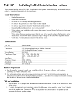
Connection Diagram
0 0 0 0 0
1 1 1 1 1
2 2 2 2 2
3 3 3 3 3
4 4 4 4 4
5 5 5 5 5
6 6 6 6 6
7 7 7 7 7
8 8 8 8 8
9 9 9 9 9
10 10 10 10 10
+12+12 -12-12
00
0
1
2
3
4
5
6
7
8
9
10
OUTPUT LEVEL
SOURCE1
ECA-70MIXAMP-1-240
POWER
SOURCE2 SOURCE3 SOURCE 4
ON
OFF
MIC1 MIC2 MIC3 MIC4 SOURCE BASS TREBLE
MASTER
Main Speaker Amp
+
-
To Additional
Speakers
+
-
+
-
+
-
+
-
Satellite
Speakers
Subwoofer

pg. 4
ECS-650-IC Owner’s Manual
Permanent Ceilings
1. Choose a location for each speaker that is free of obstructions created by joists, HVAC ductwork, electrical
wire runs, plumbing or anything else that might not allow for the depth of the speaker or create interference
or noise.
2. Onceyou have determined yourlocations,markthe hole tocutoutforthe speaker usingthesupplied
template.Don’tforgettoallowforthesizeofthespeakerbezelifyouarechoosingtoinstallthespeaker
near a side wall or other item that could become an obstacle.
3. If you are unsure of potential obstacles, carefully cut your holes using an angle to the inside of the cutout
areaasillustrated.Thiswillallowyouto‘plug’theholeeasilyifneeded.Iftheareaisclearandagood
location for the speaker, cut the edges of the opening at 90 degrees to accommodate the speaker diameter.
4. Make up the speaker wiring connection before installing the speaker. See “Wiring Connections” for
instructions.
5. Insert the speaker into the opening from below. Tighten the dogs on the speaker, making sure they clamp
onthesheetrock.Becareful-overtighteningtheclampscancausethespeakerbezeltowarpandmay
crack the ceiling.
8. Set the loudspeaker tap to the appropriate setting using the rotary switch on the front of the loudspeaker.
9. Inserttheloudspeakergrilleintothebafe,pressinggentlyoneachsideuntilitisfullyseated.
Tip: If you aren’t sure of the tap settings needed for the loudspeaker, leave the grille off so that settings
can easily be adjusted using the rotary knob.
10. Return the loudspeaker/tile assembly to the ceiling grid, attaching the removable wire connector when
appropriate.
11. Attach a security tie wire to the eyelet on top of the loudspeaker and attach the other end to the ceiling
support system per your local building code.

pg. 5
© 2013 Episode
®
ECS-650-IC Owner’s Manual
TRANSFORMER SETTING
After the speaker is installed, set the transformer to the correct setting.
Warning! Do not set the speaker for 8 ohm operation if using 70V or 100V amplier. This could cause
permanent damage to the speaker or amplier.
SPEAKER GRILLE
1. Insertthespeakergrillebypressinggentlyaroundtheedges.Thegrilleisdesignedforatighttbutwill
stillinstalleasily.Donotforceorbendthegrilleasthiscouldaffectthenaltandappearance.
2. Toremovethegrille,usethesuppliedscreenremovaltoolandcarefullypullthegrilledown.Pullthegrille
near the edges to avoid bending it with the removal tool.
70V Setting
100V Setting

pg. 6
ECS-650-IC Owner’s Manual
ECS-650-IC-4
Woofer: 4”Polypropylene
Tweeter: 1” Silk Dome
Power Handling: 40WattsRMS(@8Ω)
Nominal Impedance: 8Ohms
Tap Settings:
-70V:3.75w,7.5w,15w,30w
-100V:7.5w,15w,30w
-8ΩBypass
Frequency Response (-6dB): 65Hz-20KHz
Sensitivity -2.83 V / 1 Meter: 84dB
Crossover Frequency: 3.3 kHz
Weight: 4.5lbs.each
Grille Type: PowderCoatedPerforated
Cutout Dimensions: 7.9” Diameter
ECS-650-IC-6
Woofer: 6½”Polypropylene
Tweeter: 1” Silk Dome
Power Handling: 60WattsRMS(@8Ω)
Nominal Impedance: 8Ohms
Tap Settings:
-70V:7.5w,15w,30w,60w
-100V:15w,30w,65w
-8ΩBypass
Frequency Response (-6dB): 60Hz-20KHz
Sensitivity -2.83 V / 1 Meter: 87dB
Crossover Frequency: 2.8kHz
Weight: 5.8 lbs. each
Grille Type: PowderCoatedPerforated
Cutout Dimensions: 9.7” Diameter
SPECIFICATIONS

pg. 7
© 2013 Episode
®
ECS-650-IC Owner’s Manual
ECS-650-ICSUB-8
Woofer: 8”Polypropylene
Power Handling: 100WattsRMS(@8Ω)
Nominal Impedance: 8Ohms
Tap Settings:
-70V:10w,20w,40w,80w
-100V:20w,40w,80w
-8ΩBypass
Frequency Response (-6dB): 50Hz-120Hz
Sensitivity -2.83 V / 1 Meter: 86dB
Weight: 10.5 lbs. each
Grille Type: PowderCoatedPerforated
Cutout Dimensions: 12.2”Diameter

pg. 8
ECS-650-IC Owner’s Manual
TROUBLESHOOTING
CONTACTING TECHNICAL SUPPORT
WARRANTY
Episode
®
speakers are designed to function trouble-free. Most problems that occur are due to simple issues.
Ifyouhave trouble, please check thelist of simple xesbelow.If the problem persists, contactEpisode®
CustomerServiceat1.866.838.5052
Phone: (866)838-5052
Email: Techsupport@snapav.com
130510-1000
©2013Episode
®
Limited Lifetime Warranty
Episode
®
in-wall, in-ceiling and bookshelf Speakers have a Lifetime Limited
Warranty. This warranty includes parts and labor repairs on all components
found to be defective in material or workmanship under normal conditions
of use. This warranty shall not apply to products which have been abused,
modiedordisassembled.Productstoberepairedunderthiswarrantymust
bereturnedtoSnapAVoradesignatedservicecenterwithpriornotication
andanassignedreturnauthorizationnumber(RA).
No Sound
• Verifythatthereisaudiocomingfromthesourceselected.Selectanothersourceifnecessary.
• Ensurethattheaudiosourceisturnedonandconnectedproperly.
Lifetime
/