Page is loading ...

®
SuperWorkstation
5038A-IL
SUPER
USER’S MANUAL
1.0

The information in this User’s Manual has been carefully reviewed and is believed to be accurate.
The vendor assumes no responsibility for any inaccuracies that may be contained in this document,
makes no commitment to update or to keep current the information in this manual, or to notify any
person or organization of the updates. Please Note: For the most up-to-date version of this
manual, please see our web site at www.supermicro.com.
Super Micro Computer, Inc. ("Supermicro") reserves the right to make changes to the product
described in this manual at any time and without notice. This product, including software and docu-
mentation, is the property of Supermicro and/or its licensors, and is supplied only under a license.
Any use or reproduction of this product is not allowed, except as expressly permitted by the terms
of said license.
IN NO EVENT WILL SUPERMICRO BE LIABLE FOR DIRECT, INDIRECT, SPECIAL, INCIDENTAL,
SPECULATIVE OR CONSEQUENTIAL DAMAGES ARISING FROM THE USE OR INABILITY TO
USE THIS PRODUCT OR DOCUMENTATION, EVEN IF ADVISED OF THE POSSIBILITY OF
SUCH DAMAGES. IN PARTICULAR, SUPERMICRO SHALL NOT HAVE LIABILITY FOR ANY
HARDWARE, SOFTWARE, OR DATA STORED OR USED WITH THE PRODUCT, INCLUDING THE
COSTS OF REPAIRING, REPLACING, INTEGRATING, INSTALLING OR RECOVERING SUCH
HARDWARE, SOFTWARE, OR DATA.
Any disputes arising between manufacturer and customer shall be governed by the laws of Santa
Clara County in the State of California, USA. The State of California, County of Santa Clara shall
be the exclusive venue for the resolution of any such disputes. Super Micro's total liability for all
claims will not exceed the price paid for the hardware product.
FCC Statement: This equipment has been tested and found to comply with the limits for a Class A
digital device pursuant to Part 15 of the FCC Rules. These limits are designed to provide reasonable
protection against harmful interference when the equipment is operated in a commercial environ-
ment. This equipment generates, uses, and can radiate radio frequency energy and, if not installed
and used in accordance with the manufacturer’s instruction manual, may cause harmful interference
with radio communications. Operation of this equipment in a residential area is likely to cause harmful
interference, in which case you will be required to correct the interference at your own expense.
California Best Management Practices Regulations for Perchlorate Materials: This Perchlorate warn-
ing applies only to products containing CR (Manganese Dioxide) Lithium coin cells. “Perchlorate
Material-special handling may apply. See www.dtsc.ca.gov/hazardouswaste/perchlorate”
WARNING: Handling of lead solder materials used in this
product may expose you to lead, a chemical known to the
State of California to cause birth defects and other repro-
ductive harm.
Manual Revision 1.0
Release Date: June 14, 2013
Unless you request and receive written permission from Super Micro Computer, Inc., you may not
copy any part of this document.
Information in this document is subject to change without notice. Other products and companies
referred to herein are trademarks or registered trademarks of their respective companies or mark
holders.
Copyright © 2013 by Super Micro Computer, Inc.
All rights reserved.
Printed in the United States of America

iii
Preface
Preface
About This Manual
This manual is written for professional system integrators and PC technicians. It
provides information for the installation and use of the SuperWorkstation 5038A-IL.
Installation and maintenance should be performed by experienced technicians only.
The SuperWorkstation 5038A-IL is a high-end system based on the SC732D4F-
500B tower chassis and the X10SAE serverboard.
Manual Organization
Chapter 1: Introduction
The fi rst chapter provides a checklist of the main components included with the
system and describes the main features of the X10SAE serverboard and the
SC732D4F-500B chassis.
Chapter 2: Installation
This chapter describes the steps necessary to setup the SuperWorkstation 5038A-IL
into a rack and check out the server confi guration prior to powering up the system. If
your system was ordered without processor and memory components, this chapter
will refer you to the appropriate sections of the manual for their installation.
Chapter 3: System Interface
Refer here for details on the system interface, which includes the functions and
information provided by the control panel on the chassis as well as other LEDs
located throughout the system.
Chapter 4: Standardized Warning Statements
You should thoroughly familiarize yourself with this chapter for a general overview
of safety precautions that should be followed when installing and servicing the
SuperWorkstation 5038A-IL.

SuperWorkstation 5038A-IL User's Manual
iv
Chapter 5: Advanced Serverboard Setup
Chapter 5 provides detailed information on the X10SAE serverboard, including the
locations and functions of connections, headers and jumpers. Refer to this chapter
when adding or removing processors or main memory and when reconfi guring the
serverboard.
Chapter 6: Advanced Chassis Setup
Refer to Chapter 6 for detailed information on the SC732D4F-500B chassis. You
should follow the procedures given in this chapter when installing, removing or
reconfi guring SAS/SATA or peripheral drives and when replacing system power
supply units and cooling fans.
Chapter 7: BIOS
The BIOS chapter includes an introduction to BIOS and provides detailed informa-
tion on running the CMOS Setup Utility.
Appendix A: BIOS Error Beep Codes
Appendix B: System Specifi cations

v
Preface
Notes

vi
SuperWorkstation 5038A-IL User's Manual
Table of Contents
Chapter 1 Introduction
1-1 Overview .........................................................................................................1-1
1-2 Serverboard Features .....................................................................................1-2
Processors ......................................................................................................1-2
Memory ...........................................................................................................1-2
SATA ................................................................................................................1-2
PCI Expansion Slots .......................................................................................1-2
Onboard Controllers/Ports ..............................................................................1-2
1-3 Chassis Features ............................................................................................1-3
System Power ................................................................................................. 1-3
SATA Subsystem .............................................................................................1-3
Front Control Panel ......................................................................................... 1-3
Cooling System ............................................................................................... 1-3
1-4 Contacting Supermicro ....................................................................................1-5
Chapter 2 Installation
2-1 Overview .........................................................................................................2-1
2-2 Unpacking the System ....................................................................................2-1
2-3 Warnings and Precautions .............................................................................. 2-1
2-3 Accessing the Inside of the System................................................................2-2
Chapter 3 System Interface
3-1 Overview .........................................................................................................3-1
3-2 Control Panel Button .......................................................................................3-1
Power ..............................................................................................................3-1
3-3 Communications Panel Components .............................................................. 3-1
3-4 Control Panel LEDs ........................................................................................3-2
NIC ..................................................................................................................3-2
HDD ................................................................................................................. 3-2
Overheat/Fan Fail ...........................................................................................3-3
3-4 Drive Carrier LEDs ..........................................................................................3-3
Chapter 4 Standardized Warning Statements for AC Systems
4-1 About Standardized Warning Statements ....................................................... 4-1
Warning Defi nition ...........................................................................................4-1
Installation Instructions ....................................................................................4-4

vii
Table of Contents
Circuit Breaker ................................................................................................ 4-5
Power Disconnection Warning ........................................................................ 4-6
Equipment Installation .....................................................................................4-8
Restricted Area ................................................................................................ 4-9
Battery Handling ............................................................................................4-10
Redundant Power Supplies ..........................................................................4-12
Backplane Voltage ........................................................................................4-13
Comply with Local and National Electrical Codes ........................................ 4-14
Product Disposal ........................................................................................... 4-15
Hot Swap Fan Warning ................................................................................. 4-16
Power Cable and AC Adapter ...................................................................... 4-18
Chapter 5 Advanced Serverboard Setup
5-1 Handling the Serverboard ...............................................................................5-1
Precautions .....................................................................................................5-1
Unpacking .......................................................................................................5-1
5-2 Connecting Cables ..........................................................................................5-2
Connecting Data Cables .................................................................................5-2
Connecting Power Cables ..............................................................................5-2
Connecting the Control Panel ......................................................................... 5-2
5-3 I/O Ports ..........................................................................................................5-3
5-4 Processor and Heatsink Installation................................................................5-4
Installing an LGA 1150 Processor ................................................................... 5-4
Installing the Heatsink ..................................................................................... 5-6
Removing the Heatsink ................................................................................... 5-7
5-5 Installing Memory Modules ............................................................................. 5-8
Installing & Removing DIMMs .........................................................................5-8
5-6 Adding PCI Add-On Cards .............................................................................5-11
5-7 Serverboard Details ...................................................................................... 5-12
X10SAE Quick Reference ............................................................................. 5-12
5-8 Connector Defi nitions ................................................................................... 5-14
5-9 Jumper Settings ............................................................................................5-21
5-10 Onboard Indicators ........................................................................................5-24
5-11 SATA Ports ....................................................................................................5-24
5-12 Installing Software .........................................................................................5-25
SuperDoctor III .............................................................................................. 5-26
5-13 Onboard Battery ............................................................................................5-27

viii
SuperWorkstation 5038A-IL User's Manual
Chapter 6 Advanced Chassis Setup
6-1 Static-Sensitive Devices ..................................................................................6-1
Precautions .....................................................................................................6-1
Unpacking .......................................................................................................6-1
6-2 Accessing the Inside of the System................................................................6-2
6-3 Rotating the Hard Drive Cage.........................................................................6-3
6-4 Removing and Installing 3.5" Hard Drives ...................................................... 6-4
6-5 Removing and Installing 2.5" Hard Drives ...................................................... 6-7
6-6 Installing a 3.5" Device ................................................................................... 6-9
6-7 Installing System Fans ..................................................................................6-10
6-8 Installing the Front Bezel ..............................................................................6-12
6-9 Power Supply ................................................................................................ 6-13
Chapter 7 BIOS
7-1 Introduction ...................................................................................................... 7-1
Starting BIOS Setup Utility .............................................................................. 7-1
How To Change the Confi guration Data ......................................................... 7-1
How to Start the Setup Utility .........................................................................7-2
7-2 Main Setup ...................................................................................................... 7-2
7-3 Advanced Setup Confi gurations......................................................................7-4
7-4 Event Logs ....................................................................................................7-27
7-5 Boot Settings .................................................................................................7-29
7-6 Security Settings ...........................................................................................7-31
7-7 Save & Exit ................................................................................................... 7-32
Appendix A BIOS Error Beep Codes
Appendix B System Specifi cations

Chapter 1
Introduction
1-1 Overview
The 5038A-IL is a high-end workstation comprised of two main subsystems: the
SC732D4F-500B tower chassis and the X10SAE single Intel® Xeon® processor
serverboard. Please refer to our web site for information on operating systems that
have been certifi ed for use with the SuperWorkstation 5038A-IL (www.supermicro.
com).
In addition to the serverboard and chassis, various hardware components have
been included with the SuperWorkstation 5038A-IL, as listed below:
• Two 12-cm PWM "SuperQuiet" chassis fans (FAN-0124L4)
Optional:
• One active CPU heatsink (SNK-P0046A4)
Chapter 1: Introduction
1-1

SuperWorkstation 5038A-IL User's Manual
1-2
1-2 Serverboard Features
At the heart of the SuperWorkstation 5038A-IL lies the X10SAE, a single processor
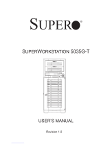
serverboard based on the Intel® C226 chipset. Below are the main features of the
X10SAE. (See Figure 1-1 for a block diagram of the chipset).
Processors
The X10SAE supports a single Intel Xeon E3-1200V3 series processor or 4th Gen-
eration Intel Core™ i7/i5/i3 DT processor in an LGA1150 socket. Please refer to the
serverboard description pages on our web site for a complete listing of supported
processors (www.supermicro.com).
Memory
The X10SAE has four DIMM slots that can support up to 32 GB of Unbuffered ECC/
non-ECC DDR3-1600/1333/1066 DIMMs. See Chapter 5 for details.
SATA
A SATA controller is integrated into the chipset to provide a SATA subsystem that
supports RAID 0, 1, 5 and 10. The X10SAE supports six SATA 3.0 (RAID 0, 1, 5,
10 supported by PCH) and two additional SATA 3.0 ports (RAID 0, 1 supported by
ASM1061(R)). RAID 5 is not supported with Linux OS.
PCI Expansion Slots
The X10SAE has one PCI-E 3.0 x16, one PCI-E 3.0 x8 (in a x16 slot), three PCI-E
2.0 x1 and two PCI-32 slots.
Onboard Controllers/Ports
The rear I/O ports include a VGA port, four USB 2.0 ports, two USB 3.0 ports, a
combination PS/2 mouse/keyboard port, a DVI port, an HDMI port two Gb Ethernet
ports and six HDA (High Defi nition Audio) ports.

1-3
Chapter 1: Introduction
1-3 Chassis Features
The SC732D4F-500B is mid-tower chassis. The following is a general outline of the
main features of the chassis.
System Power
The 5038A-IL features a single 500W power supply. This power supply unit has
been designed to operate at a low noise level to make it ideal for use in a worksta-
tion environment.
SATA Subsystem
The SC732D4F-500B chassis was designed to support eight SATA hard drives.
Front Control Panel
The control panel on the SuperWorkstation 5038A-IL includes system monitoring
LEDs and a main power button. In addition, two IEEE 1394a ports, two USB 2.0
ports, two USB 3.0 ports, one audio port and one microphone port are included on
the control panel. See Chapter 3 for details.
Cooling System
The SC732D4F-500B chassis has an innovative "Super Quiet" cooling design that
provides suffi cient cooling at very low noise level - ideal for a workplace environ-
ment. The chassis includes one 12-cm rear exhaust fan and an optional 12-cm
front cooling fan.

SuperWorkstation 5038A-IL User's Manual
1-4
Figure 1-1. Intel C226 Chipset:
System Block Diagram
Note: This is a general block diagram. Please see Chapter 5 for details.
1600/1333/1066MHz
4 USB 3.0 PORTS
5Gbps
USB3.0
VRD12.5
INTEL LGA1150
PCIe x16 SLOT #6
PCIe3.0_x16
8.0GT/s
SVID
VRM 12.5
DDR3 (CHA)
DIMM1B (Black)
DIMM1A (Blue)
DDR3 (CHB)
DIMM2B(Black)
DIMM2A (Blue)
1600/1333/1066MHz
5GT/s
x4 DMI
PCIe2.0_x1
5GT/s
PCIe x1 SLOT #3
PCIe x1 SLOT #5
PCIe2.0_x1
5GT/s
SATA-III
10 USB 2.0 PORTS
600MB/s
480Mbps
USB2.0
6 SATA-III PORTS
RJ45
2.5GT/s
PCIe2.0_x1 GLAN1
i217V
PCH
Intel
(Socket-H3)
2.7 Gb/s
x2 FDI
Analog port A
AZALIA
RealTEK ALC1150
VGA
RJ45
2.5GT/s
PCIe2.0_x1 GLAN2
i210IT
FLASH
SPI 128Mb
SPI
Display Port
HDMI
DVI-D
TPM1.2 (Header)
uPD720202
USB3.0 X2
HEALTH
INFO
COM1/2
NCT6776D
LPC I/O
ASMedia Switch
PCIe3.0_x8
8.0GT/s
ASM1480
PCIe3.0_x8
8.0GT/s
PCIe3.0_x8
8.0GT/s
PCIe x8 SLOT #4
PCIe x1 SLOT #7
PCIe2.0_x1
5GT/s
LPC
ASM1061
SATA6G X2
IDT 89HMPEB383
PCIE/PCI Bridge
PCIe2.0_x1
PCIe2.0_x1
PCIe2.0_x1
2.5GT/s
2.5GT/s
2.5GT/s
PCI Slot #1
PCI Slot #2
TI 1394
5V PCI
5V PCI
5V PCI
33MHz
33MHz
33MHz

1-5
Chapter 1: Introduction
1-4 Contacting Supermicro
Headquarters
Address: Super Micro Computer, Inc.
980 Rock Ave.
San Jose, CA 95131 U.S.A.
Tel: +1 (408) 503-8000
Fax: +1 (408) 503-8008
Email: [email protected] (General Information)
[email protected] (Technical Support)
Web Site:
www.supermicro.com
Europe
Address: Super Micro Computer B.V.
Het Sterrenbeeld 28, 5215 ML
's-Hertogenbosch, The Netherlands
Tel: +31 (0) 73-6400390
Fax: +31 (0) 73-6416525
Email: [email protected] (General Information)
[email protected] (Technical Support)
[email protected] (Customer Support)
Asia-Pacifi c
Address: Super Micro Computer, Inc.
3F, No. 150, Jian 1st Rd.
Zhonghe Dist., New Taipei City 23511
Taiwan (R.O.C)
Tel: +886-(2) 8226-3990
Fax: +886-(2) 8226-3992
Web Site:
www.supermicro.com.tw
Technical Support:
Email: [email protected]
Tel: +886-(2)-8226-3990

SuperWorkstation 5038A-IL User's Manual
1-6
Notes

Chapter 2: Installation
2-1
Chapter 2
Installation
2-1 Overview
This chapter provides a quick setup checklist to get your SuperWorkstation 5038A-IL
up and running. Following these steps in the order given should enable you to have
the system operational within a minimum amount of time. This quick setup assumes
that your system has come to you with the processor and memory preinstalled. If
your system is not already fully integrated with a serverboard, processor, system
memory etc., please turn to the chapter or section noted in each step for details on
installing specifi c components.
2-2 Unpacking the System
You should inspect the box the system was shipped in and note if it was damaged
in any way. If the system itself shows damage you should fi le a damage claim with
the carrier who delivered it.
Decide on a suitable location for the SuperWorkstation. It should be situated in
a clean, dust-free area that is well ventilated. Avoid areas where heat, electrical
noise and electromagnetic fi elds are generated. You will also need it placed near
a grounded power outlet. Be sure to read the Rack and Server Precautions in the
next section.
2-3 Warnings and Precautions
• Ensure that the caster wheels on the workstation are locked.
• Review the electrical and general safety precautions in Chapter 4.
• Use a regulating uninterruptible power supply (UPS) to protect the workstation
from power surges, voltage spikes and to keep your system operating in case
of a power failure.
• Allow the power supply units and hot-swap SATA drives to cool before touch-
ing them.
• To maintain proper cooling, always keep all chassis panels closed and all SATA
carriers installed when not being serviced.

2-2
SuperWorkstation 5038A-IL User's Manual
Figure 2-1. Removing the Chassis Side Covers
1
3
1
6
2
2
1
5
2-3 Accessing the Inside of the System
You may need to access the system periodically to perform maintenance or install
components such as hard drives. The SC732 features two removable side covers,
allowing easy access to the chassis interior.
Removing the Side Covers
1. Disconnect the chassis from any power souce.
2. Remove the two screws securing the left side cover to the chassis.
3. Slide the left cover toward the rear of the chassis.
4. Lift the left cover from the chassis.
5. Remove the three screws securing the right side cover to the chassis.
6. Slide the right cover toward the rear of the chassis
7. Lift the right cover from the chassis.

Chapter 3: System Interface
3-1
Chapter 3
System Interface
3-1 Overview
The control panel on the 5038A-IL has several LEDs and a power button. These
LEDs keep you constantly informed of the overall status of the system and the
activity and health of specifi c components.
3-2 Control Panel Button
A single push-button is located on the front of the chassis.
Power
3-3 Communications Panel Components
The SC732D4F features a front communication panel allowing easy access to the
chassis communication ports. The chassis models are equipped as follows:
• Two USB 3.0 ports
• Two USB 2.0 ports
• Two IEEE 1394A ports
• One audio port
• One microphone port
See diagram on the following page.
This is the main power button, which is used to apply or turn off the main system
power. Turning off system power with this button removes the main power but keeps
standby power supplied to the system.

3-2
SuperWorkstation 5038A-IL User's Manual
HDD
Indicates IDE channel activity on the SAS, SATA and/or DVD-ROM drive when
fl ashing.
NIC
Indicates network activity on the LAN port(s) when fl ashing.
3-4 Control Panel LEDs
The control panel located on the front of the SC732 chassis has three LEDs. These
LEDs provide you with critical information related to different parts of the system.
This section explains what each LED indicates when illuminated and any corrective
action you may need to take.
Power
Button
Audio
2x USB 2.0
2x USB 3.0
Mic
NIC LED
HDD LED
OH LED
2x 1394a

Chapter 3: System Interface
3-3
Overheat/Fan Fail
When this LED fl ashes, it indicates a chassis fan failure. When on continuously it
indicates an overheat condition, which may be caused by cables obstructing the
airfl ow in the system or the ambient room temperature being too warm. Check the
routing of the cables and make sure all fans are present and operating normally.
You should also check to make sure that the chassis covers are installed. Finally,
verify that the heatsinks are installed properly (see Chapter 5). This LED will remain
fl ashing or on as long as the indicated condition exists.

3-4
SuperWorkstation 5038A-IL User's Manual
Notes
/