Datalogic DS8100A Reference guide
- Category
- Bar code readers
- Type
- Reference guide
This manual is also suitable for

DS8100A
Reference Manual

Datalogic Automation Srl
Via Lavino, 265
40050 - Monte S. Pietro
Bologna - Italy
DS8100A Reference Manual
Ed.: 10/2012
© 2005 – 2012 Datalogic Automation S.r.l. ALL RIGHTS RESERVED. Protected to the fullest
extent under U.S. and international laws. Copying, or altering of this document is prohibited without
express written consent from Datalogic Automation S.r.l.
Datalogic and the Datalogic logo are registered trademarks of Datalogic S.p.A. in many countries,
including the U.S.A. and the E.U.
Genius, PackTrack, ACR, ASTRA, CD SQUARE and ID-NET are trademarks of Datalogic Automation
S.r.l. All other brand and product names mentioned herein are for identification purposes only and may
be trademarks or registered trademarks of their respective owners.
Datalogic shall not be liable for technical or editorial errors or omissions contained herein, nor for
incidental or consequential damages resulting from the use of this material.
02/10/12

iii
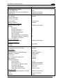
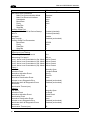
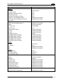
CONTENTS
REFERENCES ............................................................................................................vi
Reference Documentation........................................................................................... vi
Services and Support .................................................................................................. vi
Patents......................................................................................................................... vi
COMPLIANCE............................................................................................................vii
Electrical Safety...........................................................................................................vii
Laser Safety.................................................................................................................vii
Power Supply..............................................................................................................viii
CE Compliance...........................................................................................................viii
FCC Compliance ......................................................................................................... ix
GENERAL VIEW..........................................................................................................x
GUIDE TO INSTALLATION .......................................................................................xii
Point-to-Point Installation.............................................................................................xii
Master/Slave Lonworks Installation ............................................................................xiii
1 INTRODUCTION ..........................................................................................................1
1.1 Product Description ......................................................................................................1
1.2 Applications ..................................................................................................................1
1.3 Model Description.........................................................................................................3
1.4 Oscillating Mirror Models ..............................................................................................3
1.5 Indicators ......................................................................................................................4
1.6 Keypad and Display......................................................................................................5
1.6.1 Internal Net ...................................................................................................................5
1.6.2 Test Mode.....................................................................................................................5
1.6.3 PackTrack (Auto)..........................................................................................................6
1.7 Auto PackTrack™ Calibration for Reading Station Using Scanner Menu ....................7
1.7.1 Auto PackTrack Conditions and Limits.........................................................................7
1.7.2 Auto PackTrack Parameter Descriptions......................................................................8
1.7.3 Auto PackTrack Setup..................................................................................................9
1.8 Accessories ................................................................................................................12
2 INSTALLATION .........................................................................................................14
2.1 Package Contents ......................................................................................................14
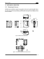
2.2 Mechanical Mounting..................................................................................................15
2.2.1 Mounting the Scanner.................................................................................................15
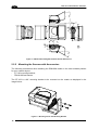
2.2.2 Mounting the Scanner with Accessories.....................................................................16
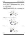
2.3 Positioning the Scanner..............................................................................................18
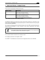
3 CBX ELECTRICAL CONNECTIONS.........................................................................19
3.1 Power Supply..............................................................................................................21
3.2 Main Serial Interface...................................................................................................21
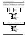
3.2.1 RS232 Interface..........................................................................................................22
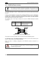
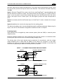
3.2.2 RS485 Full-Duplex Interface.......................................................................................23
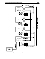
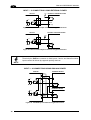
3.2.3 RS485 Half-Duplex Interface......................................................................................24
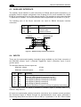
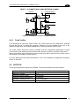
3.3 Auxiliary RS232 Interface ...........................................................................................26
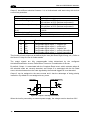
3.4 Inputs..........................................................................................................................27
3.4.1 Code Verifier...............................................................................................................31
3.5 Outputs .......................................................................................................................31

iv
3.6
User Interface - Host...................................................................................................34
4 CUSTOM CABLE ELECTRICAL CONNECTIONS ...................................................35
4.1 Power Supply..............................................................................................................37
4.2 Main Serial Interface...................................................................................................37
4.2.1 RS232 Interface..........................................................................................................38
4.2.2 RS485 Full-Duplex Interface.......................................................................................39
4.2.3 RS485 Half-Duplex Interface......................................................................................40
4.3 Auxiliary Interface .......................................................................................................42
4.4 Inputs..........................................................................................................................42
4.4.1 Code Verifier...............................................................................................................45
4.5 Outputs .......................................................................................................................45
4.6 User Interface .............................................................................................................47
5 LONWORKS CONNECTIONS...................................................................................48
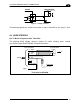
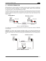
5.1 Network Termination...................................................................................................49
5.2 Lonworks Interface .....................................................................................................50
6 FIELDBUS CONNECTIONS ......................................................................................52
6.1 Ethernet Interface .......................................................................................................52
6.2 Ethernet Interface (older models) ...............................................................................53
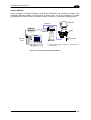
7 TYPICAL LAYOUTS ..................................................................................................55
7.1 Local Lonworks Network.............................................................................................55
7.1.1 Small Synchronized Network......................................................................................56
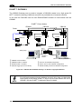
7.1.2 Large Synchronized Network......................................................................................58
7.1.3 Redundant System .....................................................................................................60
7.1.4 Multidata Network.......................................................................................................62
7.1.5 Fieldbus Networks ......................................................................................................63
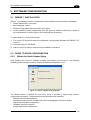
8 SOFTWARE CONFIGURATION................................................................................65
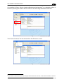
8.1 Genius™ Installation...................................................................................................65
8.2 Guide to Rapid Configuration .....................................................................................65
8.2.1 Wizard for Quick Reader Setup..................................................................................65
8.2.2 Genius™ Network Setup Through Master..................................................................68
8.2.3 Alternative Slave Address Assignment.......................................................................73
8.3 Advanced Genius™ Configuration .............................................................................73
8.3.1 Genius™ Shortcuts for Network Configuration...........................................................74
8.4 Parameter Default Values...........................................................................................76
9 READING FEATURES...............................................................................................81
9.1 Advanced Code Reconstruction (ACR™ 4)................................................................81
9.1.1 Tilt Angle for Advanced Code Reconstruction............................................................81
9.2 PackTrack™ ...............................................................................................................82
9.2.1 Auto PackTrack™ Calibration for Reading Station Using DLAPC..............................84
9.2.2 Manual PackTrack™ Calibration for DS8100A Scanner Using SPY..........................91
9.2.3 PackTrack™ Calibration for DS8100A Oscillating Mirror Models...............................94
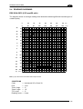
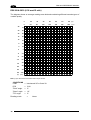
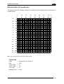
9.3 Performance ...............................................................................................................95
9.3.1 Reading Conditions ....................................................................................................95
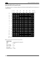
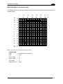
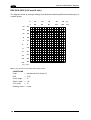
9.4 Reading Diagrams......................................................................................................97
10 MAINTENANCE .......................................................................................................107
10.1 Cleaning....................................................................................................................107
10.2 External Memory Backup & Restore.........................................................................107
10.3 Automatic Scanner Replacement (ASR) ..................................................................107

v
10.3.1
ASR Network Configuration......................................................................................108
10.3.2 Scanner Replacement Procedure.............................................................................108
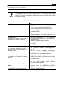
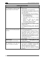
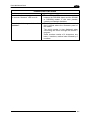
11 TROUBLESHOOTING .............................................................................................109
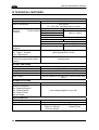
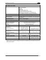
12 TECHNICAL FEATURES.........................................................................................112
A ALTERNATIVE LAYOUTS ......................................................................................114
Point-to-Point............................................................................................................114
ID-NET™ Gateway...................................................................................................116
Pass Through ...........................................................................................................117
RS232 Master/Slave.................................................................................................118
Multiplexer ................................................................................................................120
GLOSSARY..............................................................................................................121
INDEX.......................................................................................................................124

vi
REFERENCES
REFERENCE DOCUMENTATION
The documentation related to the DS8100A management is listed below:
PWR series power supply unit Installation Manuals
SC6000 Controller Reference Manual
PWO power supply unit Installation Manual
GFC-80 90° Deflecting Mirror
GFC-800A Adjustable Mirror for Close Distance Reading
CBX100/500 Installation Manuals
Document about the Ethernet connectivity
ID-NET™ Fixed Baudrate Application Note
Help On-Line in PDF format
SERVICES AND SUPPORT
Datalogic provides several services as well as technical support through its website. Log on
to www.automation.datalogic.com and click on the links
indicated for further information:
PRODUCTS
Search through the links to arrive at your product page which describes specific Info,
Features, Applications, Models, Accessories, and Downloads including the Genius™
utility program, which allows device configuration using a PC. It provides RS232 and
Ethernet interface configuration.
SERVICE
- Overview
- Warranty Extensions and Maintenance Agreements
- Sales Network
- Listing of Subsidiaries, Repair Centers, Partners
- Helpdesk
- Material Return Authorization
PATENTS
This product is covered by one or more of the following patents:
U.S. patents: Re. 36,251; 5,992,740; 6,347,740 B1; 6,177,979 B1; 6,394,352 B1;
6,443,360 B1; 6,527,184 B1; 6,629,639 B2; 6,742,710 B2; 7,161,685 B1.
European patents: 652,530 B1; 789,315 B1; 851,376 B1; 926,615 B1; 959,426 B9;
1,217,571 B1; 1,363,228 B1; 1,607,901 B1.
Japanese patents: 3,793,585 B2; 4,033,958 B2; 4,376,353 B2.

vii
COMPLIANCE
ELECTRICAL SAFETY
This product conforms to the applicable requirements contained in the European Standard for
electrical safety EN-60950 at the date of manufacture.
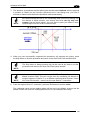
WARNING
This symbol refers to operations that must be performed by qualified
personnel only. Example: opening the device.
WARNING
This symbol refers to operations where there is danger of electrical
shock. Before opening the device make sure the power cable is
disconnected to avoid electric shock.
LASER SAFETY
The following information is provided to comply with the rules imposed by international
authorities and refers to the correct use of the DS8100A scanner.
Standard Regulations
This scanner utilizes up to 4 low-power laser diodes. Although staring directly at the laser
beam momentarily causes no known biological damage, avoid staring at the beam as one
would with any very strong light source, such as the sun.
Avoid that the laser beam hits the eye of an observer, even through reflective surfaces such
as mirrors, etc.
This product conforms to the applicable requirements of both EN60825-1 and
CDRH 21 CFR1040 at the date of manufacture. The reader is classified as a Class 2 laser
product according to EN60825-1 regulations and as a Class II laser product according to
CDRH regulations.
There is a safety device which allows the laser to be switched on only if the motor is rotating
above the threshold for its correct scanning speed.
WARNING
Use of controls or adjustments or performance of procedures other than those
specified herein may result in exposure to hazardous visible laser light.
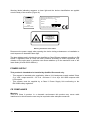
The laser light is visible to the human eye and is emitted from the window on the side of the
scanner (Figure A).

viii
Warning labels indicating exposure to laser light and the device classification are applied
onto the body of the scanner (Figure A):
AVOID EXPOSURE
LASER LIGHT IS EMITTED
FROM THIS APERTURE
CAUTION-CLASS 3B
LASER LIGHT
WHEN OPEN
AVOID
EXPOSURE TO BEAM
Model No. Amp.
Serial No.
DATALOGIC AUTOMATION S.r.l. - Via Lavino 265
40050 Monte San Pietro - Bologna - Italy
Manufactured Volt
This product conforms to the applicable requirements
of 21CFR1040 at the date of manufacture.
LASER LI GHT
DO N OT STAR E I NT O BE AM
C LASS 2 LASE R PRO DU CT
MAXIMUM OUTPUT RA DIATION 1 mW
EMI TT ED WA VEL EN GT H 630~680 nm
T O EN 60825-1:2001
Warning and Device Class Labels
Disconnect the power supply when opening the device during maintenance or installation to
avoid exposure to hazardous laser light.
The laser diodes used in this device are classified as Class 3B laser products according to EN
60825-1 regulations and as Class IIIb laser products according to CDRH regulations. Any
violation of the optic parts in particular can cause radiation up to the maximum level of the
laser diode (30 mW at 630~680 nm).
POWER SUPPLY
This product is intended to be installed by Qualified Personnel only.
- This scanner is intended to be supplied by either a UL Listed power supply marked 'Class
2' or 'LPS', output rated 20 – 30 V dc , minimum 1.3 A or by a UL Listed computer with
LPS outputs.
- This scanner must be supplied by a Class II Power Supply Unit conforming to the
EN 60950 safety regulation.
CE COMPLIANCE
Warning:
This is a Class A product. In a domestic environment this product may cause radio
interference in which case the user may be required to take adequate measures.

ix
FCC COMPLIANCE
Modifications or changes to this equipment without the expressed written approval of
Datalogic could void the authority to use the equipment.
This device complies with PART 15 of the FCC Rules. Operation is subject to the following
two conditions: (1) This device may not cause harmful interference, and (2) this device must
accept any interference received, including interference which may cause undesired
operation.
This equipment has been tested and found to comply with the limits for a Class A digital
device, pursuant to part 15 of the FCC Rules. These limits are designed to provide
reasonable protection against harmful interference when the equipment is operated in a
commercial environment. This equipment generates, uses, and can radiate radio frequency
energy and, if not installed and used in accordance with the instruction manual, may cause
harmful interference to radio communications. Operation of this equipment in a residential
area is likely to cause harmful interference in which case the user will be required to correct
the interference at his own expense.

x
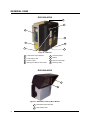
GENERAL VIEW
DS8100A-XXX0
Figure A – DS8100A
Laser Beam Output Window
Laser Safety Label
Product Label
Warning and Device Class Label
1
2
3
4
Connector Panel
Display
Service Access Cap
5
6
7
Mounting Holes
8
DS8100A-XXX5
Figure B – DS8100A Oscillating Mirror Models
Laser Beam Output Window
1
Laser Safety Label
2
1
2
1
2
8
5
3
4
6
7

xi
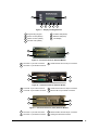
Figure C – Display and Keypad Panel
Programming Keypad
Power On LED (Green)
Phase On LED
(
Yellow
)
Encoder LED (Yellow)
1
2
3
4
TX Data LED (Green)
Network LED (Red)
LCD Display
5
6
7
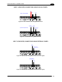
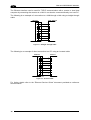
Figure D – Connector Panel for Standard Models
Lonworks 17-pin male connector
Lonworks 17-pin female connector
1
2
Serial interface and I/O 26-pin connector
3
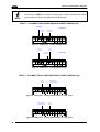
Figure E – Connector Panel for Ethernet Models
Figure F – Connector Panel for (older) Ethernet Models
Lonworks 17-pin male connector
Lonworks 17-pin female connector
Harting RJ industrial connector
1
2
4
Serial interface and I/O 26-pin connector
3
1
2
3
1
2
4
3
7
1
2 3
4 5 6
1
2
4
3
Lonworks 17-pin male connector
Lonworks 17-pin female connector
Ethernet M12 4-pin female connector
1
2
4
Serial interface and I/O 26-pin connector
3

xii
GUIDE TO INSTALLATION
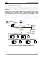
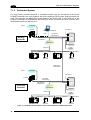
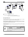
POINT-TO-POINT INSTALLATION
The following can be used as a checklist to verify all the necessary steps to complete
installation of the DS8100A scanner.
1) Read all information in the section “Safety Regulations” at the beginning of this manual.
2) Correctly mount the scanner according to the information in par. 2.2 and position it at the
correct reading distance
as shown in par. 2.3 and par. 9.4.
3)
Make electrical connections to your DS8100A scanner by:
a) Connecting the DS8100A scanner to the CBX connection box by means of one of the
CAB-F0x cables provided as accessory (see par. 1.8).
b)
Providing correct and complete system cabling through the CBX connection box
according to the signals necessary for the layout of your application (trigger, inputs,
outputs).
Cabling: Power, Interface, Inputs, Outputs, etc. For further details, see chapter 3
(chapter 4 for custom cabling).
Alternative Layouts: Point-to-Point, Pass Through, RS232 Master/Slave,
Mutliplexer. See appendix A for layout references.
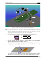
4)
Configure the DS8100A scanner by installing and running the Genius™ configuration
program from the CD-ROM provided. See chapter 8 and the Help On-Line for details.
The main steps are:
Select the codes to be read
Set-up the communication parameters
When PackTrack™ is required, perform PackTrack™ calibration
Define data formatting parameters
NOTE
Fine tuning of the scanner position for barcode reading can be
accomplished by performing a test through the SPY configuration tool in
Genius™.
5) Exit the configuration program and run your application.
The installation is now complete.

xiii
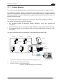
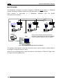
MASTER/SLAVE LONWORKS INSTALLATION
The following can be used as a checklist to verify all the steps necessary to complete
installation of the DS8100A scanner in a Master/Slave Lonworks network.
1) Read all information in the section “Safety Regulations” at the beginning of this manual.
2) Correctly mount the scanner according to the information in par. 2.2 and position it at the
correct reading distance
as shown in par. 2.3 and par. 9.4.
3)
Make electrical connections to your DS8100A scanner by:
a) Connecting the DS8100A Master
scanner to the CBX100 by means of one of the
CAB-F0x cables provided as accessory (see par. 1.8).
b)
Correctly terminating the DS8100A Master reader according to the information given
in par. 5.1 and par. 7.1.
c)
Completing the system wiring adding as many slave scanners as required by your
system layout (refer to par. 7.1).
d)
Correctly providing bus return to the last DS8100A Slave reader of the network
according to the information given in par. 5.1 and par. 7.1.
4)
Install and run the Genius™ configuration program from the CD-ROM provided.
Configure the Local Lonworks Network using one of the procedures given below
:
Configure the entire network through the Master as described in par. 8.2.2;
Configure the Master as described in par. 8.2.2 and locally define each slave scanner
address as
described in par. 8.2.3.
Define each scanner, master and slaves (with their addresses), by using the scanner
keypad according to the information given in par. 1.6.1.
5)
Configure the Master scanner through the Genius™ program. See chapter 8 and the
Help On-Line for details.
The main steps are:
Select the codes to be read
Set-up the communication parameters
When PackTrack™ is required, perform PackTrack™ calibration, see par. 9.2.1.
Define data formatting parameters
6) Configure each Slave scanner through the Master scanner using Genius™. See chapter
8 and the Help On-Line for details. The main steps are:
Select the codes to be read
When PackTrack™ is required, perform PackTrack™ calibration, see par. 9.2.1.
NOTE
Fine tuning of the scanner position for barcode reading can be
accomplished by performing a test through the SPY configuration tool in
Genius™.

xiv
7) Send the configuration to the Master.
8) Perform the External Memory Backup procedure for system backup purposes (see par.
10.2). For backward compatibility you can perform the ASR Network Configuration
procedure f
or system backup purposes (see par. 10.3.1).
9)
Exit the configuration program and run your application.
The installation is now complete.

INTRODUCTION
1
1
1 INTRODUCTION
1.1 PRODUCT DESCRIPTION
The DS8100A scanner is a barcode reader complete with decoder designed to provide an
innovative and high performance solution in omnidirectional reading applications by
combining the following advanced technologies with Datalogic solid experience in the
material handling sector.
Some of the main features of DS8100A are listed below:
scanning speed 1000 scans/sec.
reads all popular codes.
supply voltage from 20 to 30 Vdc.
test mode to verify the reading features and exact positioning of the scanner without the
need for external tools.
programmable in several different operating modes to suit the most various barcode
reading system requirements.
light source: solid state laser diodes; the light emitted has a wave length between
630~680 nm. For laser safety precautions refer to the “Compliance” section at the
beginning of this manual.
1.2 APPLICATIONS
The DS8100A barcode reader is specifically designed for industrial applications and for all
cases requiring high reading performance such as:
code reconstruction
reading of codes covered by plastic film
reading of codes with a wide depth of field
reading of high resolution codes positioned at long distances from the reader
code reading on fast moving objects.
DS8100A is designed for both single-reader layouts and multi-reader layouts. For typical
layouts see chapter 7 and appendix A.

DS8100A REFERENCE MANUAL
2
1
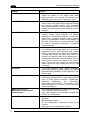
Feature
Benefit
ACR™
Advanced Code Reconstruction technology
allows the reading of low aspect ratio labels
placed anywhere on a parcel and enhances the
readability of poorly printed or damaged codes.
CD SQUARE™
CD SQUARE™ provides useful information on
label position and object shape elaborated during
the barcode reading phase. This innovative
technology identifies the area in which the code is
located and measures the code distance from the
scanner.
PACKTRACK™
PackTrack™ is a Datalogic patented parcel
tracking system which improves the reading
features in omnidirectional stations. In particular,
PackTrack™ manages 6-sided reading systems
when it is impossible to detect the real position of
the code on the parcel, thus overcoming the need
for external accessories essential in traditional
tracking systems.
ASTRA™
Automatically SwiTched Reading Area™ is the
new Datalogic technology based on a multi-laser
architecture and a fixed mounted optic system
which concentrates the multiple laser emissions in
a single laser beam. As each laser emitter is
focused on a specific range of the reading area, a
sophisticated electronic controller selects the best
focused laser emitter with respect to the code to
read. This allows the reading of medium-high
density codes in a large reading area on very fast
conveyors.
Flexibility
The high frequency laser diode modulation
system guarantees complete immunity to ambient
light and allows installation of the DS8100A in any
working area.
Reading parcels on conveyors
As a result of the ASTRA™ multiple laser
technology, DS8100A gives a great real time DOF
even on high speed conveyors. Furthermore,
DS8100A implements the Packtrack™
functionality which leads to an increase of the
plant production as a result of the augmented
system throughput.
Master working as a
Multiplexer on high speed
Lonworks bus
Great competitiveness of the offer, since the cost
of an external multiplexer is saved;
High data transfer on an industrial, reliable bus
running at 1.25 Mbit/sec.
Genius™ Configurator SW
Reduced learning time, with an easy wizard
approach;
Multilanguage platform;
All the configuration parameters stored in the
scanner;
Not dependent on the Physical interface.

INTRODUCTION
3
1
Feature
Benefit
Energy Saving
A software parameter group which allows
management of the energy saving feature. In
particular, it allows turning on/off the motor and
laser of all network scanners according to the
selected digital input, encoder, or communication
channel.
The time required to restart the system is less
than 1 minute independently from the number of
scanners connected.
It is suggested to use this parameter for example
when the conveyor is stopped for a lengthy
period.
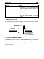
1.3 MODEL DESCRIPTION
The DS8100A scanner is available in versions that differ depending on the interface
connection, the optical resolution and on the optic version:
DS8100A - X X X
X
O
p
tic Version:
0 = Linear
O
p
tical Resolution:
0 = Low resolution
1 = Medium resolution
Communication Type:
0 = Standard version
1 = Ethernet version
2 = High resolution
3 = Very High resolution
5 = Oscillating mirror
Laser Number:
2 = Double laser
3 = Tri
p
le laser
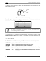
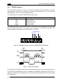
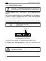
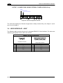
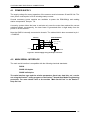
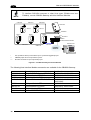
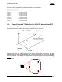
1.4 OSCILLATING MIRROR MODELS
Oscillating mirror models are used when coverage of a large reading area is required, mainly
in picket fence applications.
The oscillating mirror is placed in front of the reading aperture of the DS8100A scanner to
deflect the laser beam. As the mirror moves, this sweeping function of the laser beam allows
the coverage of a larger area to locate the barcodes. The code can also be reconstructed as
the beam sweeps over it.

DS8100A REFERENCE MANUAL
4
1
The aperture angle is symmetrical and the scan line perpendicular to the scanner is at 0° as
shown in the figure below.
0°
+25°
-25°
Figure 1- Oscillating Mirror Reference Angle
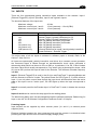
By configuring the oscillating speed up to the maximum value of 19 Hz, raster emulation can
be performed for reading fast moving objects.
Hz Max. Aperture
0-5 50°
6-10 30°
11-15 20°
16-19 10°
NOTE
By limiting the raster width to the minimum necessary, the number of scans
on the reading surface is increased.
The oscillating mirror is completely controlled by software commands and therefore avoids
complex mechanical calibrations. For details of the software configuration parameters see
the Genius™ Help On Line.
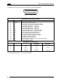
1.5 INDICATORS
The DS8100A has five LEDs on the rear panel. The indicators have the following functions:
POWER ON
(green) Indicates the scanner is turned on.
PHASE ON
(yellow) Indicates the external presence sensor is active.
ENCODER
(yellow) Indicates the external encoder signal is active.
TX DATA
(green) Indicates data transmission both on the main and on the auxiliary
interface.
NETWORK
(red) Indicates the Lonworks network is functioning correctly. This LED is
normally ON.

INTRODUCTION
5
1
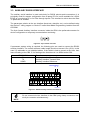
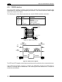
1.6 KEYPAD AND DISPLAY
The DS8100A keypad allows entering a menu for selection of one of the following functions:
Welcome: shows the current software release and operating mode;
Autolearn: starts the procedure making it possible to obtain an automatic, accurate
and fast configuration of DS8100A without the necessity of directly
checking/modifying the relevant parameters;
Internal Net: defines scanner function within the network (see below);
Ethernet Mode: allows setting the scanner IP address to be used within the network;
LCD Contrast: sets the LCD contrast ;
Bus: not used for DS8100A scanners;
Test Mode: allows verifying the scanner reading position and features (see below).
PackTrack: allows setting the Auto PackTrack Calibration procedure (see below).
The same settings may be performed by using the Genius™ program (see chapter 8 for
details).
1.6.1 Internal Net
This submenu can be used as an alternative to configuration through Genius™, to assign the
DS8100A scanner within a master/slave network.
It allows defining the scanner function (slave/master) within the network and, if configured as
Slave, its address.
To enter the Internal Net submenu and configure the scanner follow the given procedure:
1) Press and hold both the ▲ (up arrow) and ▼ (down arrow) keys for about 2 seconds to
enter the Main menu;
2) Use the ▲ (up arrow) or ▼ (down arrow) key to select the “Internal Net” item, then press
the ENT (enter) key to confirm;
3) Use the ▲ (up arrow) or ▼ (down arrow) key to select the “LonWAddrSel”” item, then
press the ENT (enter) key to confirm;
4) Use the ▲ (up arrow) or ▼ (down arrow) key to select your scanner function among
“Master”, “Slave n”, “Slave jolly”, “Disabled”; then, press the ENT (enter) key to confirm;
5) Use the ▲ (up arrow) or ▼ (down arrow) key to select the “Exit” item, then press the ENT
(enter) key to confirm. Repeat this step again to exit the Main Menu and return to the
scanner current operating mode.
1.6.2 Test Mode
Test Mode is particularly advised during the installation phase, since it causes the reader to
be continuously activated allowing verification of its reading features and its reading position
with respect to the barcode.

DS8100A REFERENCE MANUAL
6
1
To enter the Test Mode submenu and configure the scanner follow the given procedure:
1) Press and hold both the ▲ (up arrow) and ▼ (down arrow) keys for about 2 seconds to
enter the Main menu.
2) Use the ▲ (up arrow) or ▼ (down arrow) key to select the “Test Mode” item, then press
the ENT (enter) key to confirm. The reader enters Test Mode.
3) Press the ▲ (up arrow) key to exit the Test Mode.
4) Use the ▲ (up arrow) and ▼ (down arrow) key to select the “Exit” item, then press the
ENT (enter) key to confirm. The scanner exits the Main Menu and returns to its current
operating mode.
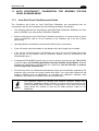
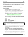
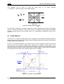
1.6.3 PackTrack (Auto)
This submenu can be used to execute the Automatic PackTrack Calibration procedure for
the Reading Station when the Master scanner is in PackTrack or Continuous Operating
Modes. Performing this procedure through the Keypad/Display Menu is an alternative to
Automatic PackTrack Calibration through the DLAPC tool in Genius™, see Help On-Line.
NOTE
This scanner must first be configured as Master of the master/slave network
(see par. 1.6.1, "Internal Net" procedure).
To enter the PackTrack submenu and configure the scanner follow the given procedure:
1) Read Par 1.7.1 regarding Auto PackTrack Conditions and Limits.
2)
Press and hold both the ▲ (up arrow) and ▼ (down arrow) keys for about 2 seconds to
enter the Main menu;
3) Use the ▲ (up arrow) or ▼ (down arrow) key to select the “PackTrack” item, then press
the ENT (enter) key to confirm;
4) Use the ▲ (up arrow) or ▼ (down arrow) key and the ENT (enter) key to select the items
in the following table and set them according to your application. See par. 1.7.2 for
details;
5)
After all items are set, use the ▲ (up arrow) or ▼ (down arrow) key to select “Start”; then,
press the ENT (enter) key to confirm. Follow the Procedure described in par. 1.7.3.
Page is loading ...
Page is loading ...
Page is loading ...
Page is loading ...
Page is loading ...
Page is loading ...
Page is loading ...
Page is loading ...
Page is loading ...
Page is loading ...
Page is loading ...
Page is loading ...
Page is loading ...
Page is loading ...
Page is loading ...
Page is loading ...
Page is loading ...
Page is loading ...
Page is loading ...
Page is loading ...
Page is loading ...
Page is loading ...
Page is loading ...
Page is loading ...
Page is loading ...
Page is loading ...
Page is loading ...
Page is loading ...
Page is loading ...
Page is loading ...
Page is loading ...
Page is loading ...
Page is loading ...
Page is loading ...
Page is loading ...
Page is loading ...
Page is loading ...
Page is loading ...
Page is loading ...
Page is loading ...
Page is loading ...
Page is loading ...
Page is loading ...
Page is loading ...
Page is loading ...
Page is loading ...
Page is loading ...
Page is loading ...
Page is loading ...
Page is loading ...
Page is loading ...
Page is loading ...
Page is loading ...
Page is loading ...
Page is loading ...
Page is loading ...
Page is loading ...
Page is loading ...
Page is loading ...
Page is loading ...
Page is loading ...
Page is loading ...
Page is loading ...
Page is loading ...
Page is loading ...
Page is loading ...
Page is loading ...
Page is loading ...
Page is loading ...
Page is loading ...
Page is loading ...
Page is loading ...
Page is loading ...
Page is loading ...
Page is loading ...
Page is loading ...
Page is loading ...
Page is loading ...
Page is loading ...
Page is loading ...
Page is loading ...
Page is loading ...
Page is loading ...
Page is loading ...
Page is loading ...
Page is loading ...
Page is loading ...
Page is loading ...
Page is loading ...
Page is loading ...
Page is loading ...
Page is loading ...
Page is loading ...
Page is loading ...
Page is loading ...
Page is loading ...
Page is loading ...
Page is loading ...
Page is loading ...
Page is loading ...
Page is loading ...
Page is loading ...
Page is loading ...
Page is loading ...
Page is loading ...
Page is loading ...
Page is loading ...
Page is loading ...
Page is loading ...
Page is loading ...
Page is loading ...
Page is loading ...
Page is loading ...
Page is loading ...
Page is loading ...
Page is loading ...
Page is loading ...
Page is loading ...
Page is loading ...
Page is loading ...
Page is loading ...
-
 1
1
-
 2
2
-
 3
3
-
 4
4
-
 5
5
-
 6
6
-
 7
7
-
 8
8
-
 9
9
-
 10
10
-
 11
11
-
 12
12
-
 13
13
-
 14
14
-
 15
15
-
 16
16
-
 17
17
-
 18
18
-
 19
19
-
 20
20
-
 21
21
-
 22
22
-
 23
23
-
 24
24
-
 25
25
-
 26
26
-
 27
27
-
 28
28
-
 29
29
-
 30
30
-
 31
31
-
 32
32
-
 33
33
-
 34
34
-
 35
35
-
 36
36
-
 37
37
-
 38
38
-
 39
39
-
 40
40
-
 41
41
-
 42
42
-
 43
43
-
 44
44
-
 45
45
-
 46
46
-
 47
47
-
 48
48
-
 49
49
-
 50
50
-
 51
51
-
 52
52
-
 53
53
-
 54
54
-
 55
55
-
 56
56
-
 57
57
-
 58
58
-
 59
59
-
 60
60
-
 61
61
-
 62
62
-
 63
63
-
 64
64
-
 65
65
-
 66
66
-
 67
67
-
 68
68
-
 69
69
-
 70
70
-
 71
71
-
 72
72
-
 73
73
-
 74
74
-
 75
75
-
 76
76
-
 77
77
-
 78
78
-
 79
79
-
 80
80
-
 81
81
-
 82
82
-
 83
83
-
 84
84
-
 85
85
-
 86
86
-
 87
87
-
 88
88
-
 89
89
-
 90
90
-
 91
91
-
 92
92
-
 93
93
-
 94
94
-
 95
95
-
 96
96
-
 97
97
-
 98
98
-
 99
99
-
 100
100
-
 101
101
-
 102
102
-
 103
103
-
 104
104
-
 105
105
-
 106
106
-
 107
107
-
 108
108
-
 109
109
-
 110
110
-
 111
111
-
 112
112
-
 113
113
-
 114
114
-
 115
115
-
 116
116
-
 117
117
-
 118
118
-
 119
119
-
 120
120
-
 121
121
-
 122
122
-
 123
123
-
 124
124
-
 125
125
-
 126
126
-
 127
127
-
 128
128
-
 129
129
-
 130
130
-
 131
131
-
 132
132
-
 133
133
-
 134
134
-
 135
135
-
 136
136
-
 137
137
-
 138
138
-
 139
139
-
 140
140
-
 141
141


Datalogic DS8100A Reference guide
- Category
- Bar code readers
- Type
- Reference guide
- This manual is also suitable for
Ask a question and I''ll find the answer in the document
Finding information in a document is now easier with AI
Related papers
-
Datalogic DS8100A-3115 Reference guide
-
-
-
-
Datalogic DX8200A-3011 User guide
-
Datalogic Scanning Connection Box CBX100 User manual
-
Datalogic CBX500 Installation guide
-
Datalogic DX8200A Installation guide
-
-
Datalogic CBX800 Installation guide
Other documents
-
Pepperl+Fuchs CBX100 Owner's manual
-
Yamaha CBX-D5 Owner's manual
-
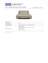
 Cables Direct SS-048 Datasheet
-
Datalogic Scanning Network Card DS2100N User manual
-
 Cables Direct SS-411 Datasheet
-
Vaisala GML20T User manual
-
-
ESD CAN-CBX-Air/2 Owner's manual
-
-
Soyal 701ServerSQL Quick start guide

