18 / 19
X
X
N
N
E
E
T
T
N
N
e
e
t
t
w
w
o
o
r
r
k
k
D
D
o
o
m
m
e
e
C
C
a
a
m
m
e
e
r
r
a
a
I
I
n
n
s
s
t
t
a
a
l
l
l
l
a
a
t
t
i
i
o
o
n
n
M
M
a
a
n
n
u
u
a
a
l
l
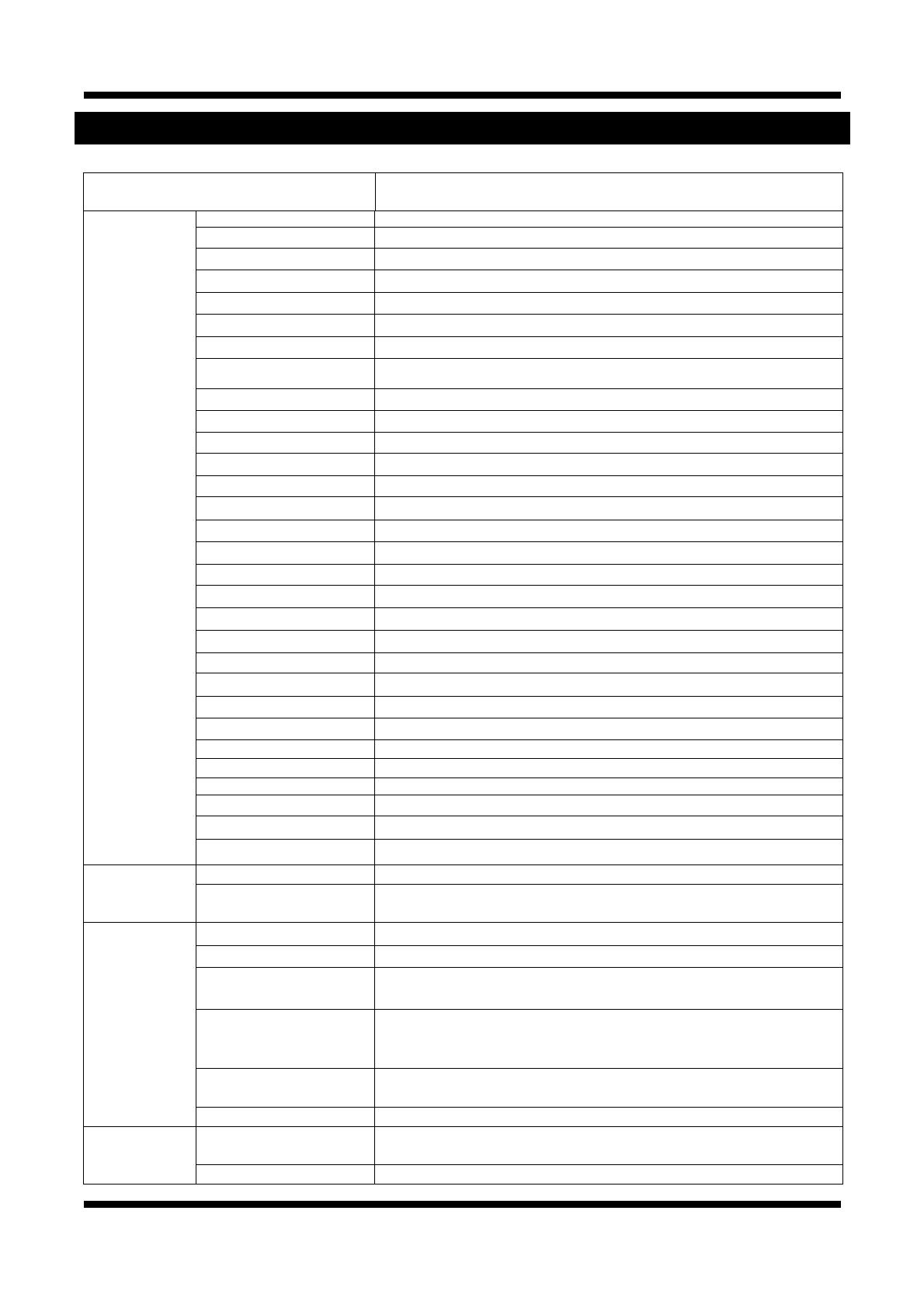
5. Specification
IDB4110NVF/ IDB4110PVF
IVB4110NVF/ IVB4110PVF
Specifications
Camera Signal System NTSC / PAL
Scanning System 10Bit Digital out - De-Interlace
Image Sensor 1/3" High sensitivity CCD
Sync. System Internal
Effective Pixel Number NTSC / 768 (H) x 494(V) PAL / 752 (H) x 582(V)
Horizontal Resolution 580 TV Lines(BW 650 TV lines)
Video Output Level 1.0Vp-p Composite Signal (BNC 75Ω)
Lens C/CS Mount, DC Iris (Recommend lens: SCVHM408D, CBC HG2Z0414FC-MP,
AMRON M13VG308, M13VG246, M12VG412
Min. Illumination 0.05 Lux (Color), 0.0002 Lux (Sens-up Auto), F1.2, 30 IRE
Back Light Compensation On/Off
White Balance ATW / PUSH / MANUAL
Exposure Control Auto/Manual
Functions B/W, Flickerless
Day & Night System AUTO / DAY / NIGHT / EXT / IRED
DSS
OFF / AUTO ⅹ(2 ~ 128)
3D-DNR ON / OFF ( 0 ~ 63)
AGC OFF / LOW / MID / HIGH
WDR Up to 60 dB (LOW / MIDDLE / HIGH)
BLC LOW / MIDDLE / HIGH
ECLIPSE ON / OFF (16 Zones)
Stabilizer ON / OFF
Digital-ZOOM
ⅹ1.00 ~ ⅹ6.13
Night Burst ON / OFF
Motion Detection ON/OFF(4 Programmable Zone)
Privacy ON/OFF(8 Programmable Zone)
D-EFFECT V – FLIP / MIRROR / ROTATE
Sharpness 1 ~ 100
Baud Rate 4800 / 9600 / 19200 / 38400 / 57600
OSD Language ENG / KOR / RSN / CHN / SPN / FRN
Electronic Shutter Speed
AUTO / OFF / A.FLK / ⅹ(2 ~ 512) / (1/90000 ~ 1/160)
System Main Processors 32bit Embedded CPU with Linux
System Memory
NAND Flash Memory : 64MB, DDR Memory : 128MB
SD Card : Support for Max 4GB Size
Video/Audio Compression MJPEG / MPEG4 / H.264
Frame rate
Dual Mode : MJPEG (15fps) MPEG4 / H.264 (30fps)
Resolution
D1 (NTSC:720 x 480, PAL:720 x 576)
CIF (NTSC:360 x 240, PAL:360 x 288)
Video streaming
MJPEG / MPEG4(or H.264) Dual mode
Constant and variable bit rate in MPEG4 (128kbps ~ 3M bps)
Controllable frame rate and bandwidth
Image settings
Compression level setting
Configurable Brightness, Sharpness, White Balance
Audio Two-way(full duplex / ADPCM G.711 or G.726)
Network Protocol
IPv4, HTTP, TCP, RTSP, RTP, RTCP, UDP,SMTP, FTP, ICMP, DHCP, UPnP, Bonjour,
ARP, DNS, DynDNS
Supported DDNS 1. DDNS 2. DynDNS.org 3. Reference code with SDK


