Page is loading ...

WARNING
Installation must be done by an electrician qualified
in the installation and service of control systems
for heating equipment.
Improper installation, adjustment, alteration, service
or maintenance can result in death, injury or
property damage. Read the Installation, Operation
and Service Manual thoroughly before installing or
servicing this equipment.
Installer
Please take the time to read and understand
these instructions prior to any installation.
Installer must give a copy of this manual to the owner.
Owner
Keep this manual in a safe place in order to provide
your service technician with necessary information.
Roberts-Gordon LLC
1250 William Street
P.O. Box 44
Buffalo, New York 14240-0044
Telephone: +1.716.852.4400
Fax: +1.716.852.0854
Toll Free: 800.828.7450
www.robertsgordon.com
© 2019 Roberts-Gordon LLC
For CORAYVAC
®
and Unitary
Infrared Heating Systems
Installation Manual
P/N 1006101NA Rev E 07/19


© 2019
Roberts-Gordon LLC
All rights reserved. No part of this work covered by the copyrights herein may be reproduced
or copied in any form or by any means - graphic, electronic, or mechanical, including
photocopying, recording, taping or information storage and retrieval systems - without the
written permission of Roberts-Gordon LLC.
TABLE OF CONTENTS
SECTION 1: Introduction........................................................1
1.1 Safety ...........................................................................1
1.2 Safety Labels and Their Placement..............................1
1.3 California Proposition 65 ..............................................1
1.4 What is a ROBERTS GORDON
®
CORAYVAC
®
Modulating Heating Control?.......................................1
1.5 What is a ROBERTS GORDON
®
COMPLETE™
Modulating Heating Control? .......................................1
1.6 General Requirements .................................................2
1.7 CORAYVAC
®
Design Requirements (Modulating
Systems) ......................................................................2
1.8 CORAYVAC
®
Design Requirements (On/Off Systems) 2
1.9 VANTAGE
®
CTHN Multiburner Systems.......................2
1.10 Unitary Design Requirements.....................................2
1.11 Control Board and Sensor Power ...............................2
1.12 Example Site Layout...................................................3
1.13 Carton Contents .........................................................8
SECTION 2: Specifications .................................................. 10
2.1 ROBERTS GORDON
®
CORAYVAC
®
Modulating
Heating Control and COMPLETE™ Modulating
Heating Control (Unitary Heaters).............................. 10
2.2 Terminating Resistor, BT485...................................... 10
2.3 Repeater .................................................................... 10
2.4 Load Reactor ............................................................. 11
2.5 Temperature Sensors................................................. 11
2.6 Touchscreen (HMI) (Located on Central Controller:... 11
2.7 Variable Frequency Drive (Located inside
CORAYVAC
®
Modulating Heating Control) ................ 11
SECTION 3: Installation........................................................13
3.1 Preparation ................................................................13
3.2 Positioning CORAYVAC
®
Modulating Heating
Control....................................................................... 15
3.3 Cable Requirements: ................................................. 16
3.4 CORAYVAC
®
and COMPLETE™ Modulating Heating
Control Installation Materials...................................... 16
3.5 Electrical Installation Requirements of CORAYVAC
®
Modulating Heating Control ....................................... 19
3.6 Pump Requirements .................................................. 19
3.7 Variable Frequency Drive Requirements....................20
3.8 Indoor Sensor Placement and Mounting ...................20
3.9 Indoor Sensor Addressing .........................................20
3.10 Outdoor Sensor (P/N 10081500) Placement ...........21
3.11 Outside Air Supply (P/N 90707501K) .......................21
SECTION 4: Typical Wiring Diagrams..................................23
SECTION 5: Communications..............................................38
5.1 WebCTRL
®
.................................................................38
5.2 BACnet/IP Connection...............................................38
5.3 Integration into Building Management
System (BMS)............................................................39
5.4 Communications Between Multiple CORAYVAC
®
Modulating Heating Controls......................................40
5.5 Setting Baud Rate......................................................41
5.6 Terminating Resistors.................................................41
5.7 Control Board Setup ..................................................42
5.8 Touchscreen...............................................................45
5.9 The REP485 Repeater (P/N 10060156).....................47
SECTION 6: Variable Frequency Drive Programming........ 48
6.1 VFD Parameter Settings For Use With ROBERTS
GORDON
®
CORAYVAC
®
Modulating Heating
Control....................................................................... 48
6.2 Altering VFD Parameters........................................... 49
6.3 Sequence of Operation CORAYVAC
®
Modulating
Heating Control ......................................................... 52
SECTION 7: Commissioning The CORAYVAC
®
System .... 55
7.1 Setting The CORAYVAC
®
End Burner Vacuum.......... 55
SECTION 8: Programming and Troubleshooting the
System.............................................................. 58
8.1 Passwords................................................................. 58
8.2 Home Screen and Programming the System ............ 59
8.3 Home Screen System Configuration ......................... 59
8.4 Zone Temperature Setpoints ..................................... 60
8.5 Schedule Creation..................................................... 60
8.6 Edit Existing Schedule .............................................. 62
8.7 Zone Configuration (Zone Setup).............................. 62
8.8 Maintenance.............................................................. 63
8.9 Alarms ....................................................................... 63
8.10 Alarm Configuration................................................. 63
8.11 VFD Status .............................................................. 63
8.12 Unit Configuration.................................................... 64
8.13 Adjust Time.............................................................. 64
SECTION 9: Troubleshooting............................................... 66
SECTION 10: Controls Start-Up Checklist ......................... 83
SECTION 11: Replacement Parts ........................................ 84
11.1 CORAYVAC
®
Modulating Heating Control Controller
Replacement Parts.................................................... 85
11.2 COMPLETE™ Modulating Heating Control Controller
Replacement Parts.................................................... 86
11.3 Repeater Replacement Parts ................................... 87
11.4 Replacement Parts Instructions ............................... 88
SECTION 12: Integration with Building Management
System (BMS) ................................................ 89
12.1 BACnet over ARC156 .............................................. 89
12.2 BACnet MS/TP ........................................................ 91
12.3 BACnet PTP ............................................................ 93
12.4 BACnet Over IP ....................................................... 94
12.5 BACnet over Ethernet.............................................. 96
12.6 Modbus ................................................................... 97
12.7 To set up the Modulating Controller for N2 on
Port 1......................................................................100
12.8 LonWorks ...............................................................102
SECTION 13: Touchscreen Tree..........................................104
SECTION 14: The ROBERTS GORDON
®
CORAYVAC
®
/
COMPLETE™ Modulating Heating Control
Limited Warranty .........................................113


SECTION 1: INTRODUCTION
1
SECTION 1: INTRODUCTION
1.1 Safety
Your Safety is Important to Us!
This symbol is used throughout
the manual to notify you of
possible fire, electrical or burn
hazards. Please pay special atten-
tion when reading and following
the warnings in these sections.
Installation, service and annual inspection of
controller must be done by an electrician qualified in
the installation and service of control systems for
heating equipment.
Installation, service and annual inspection of heater
must be done by a contractor qualified in the
installation and service of gas-fired heating
equipment.
Read this manual carefully before installation,
operation, or service of this equipment.
The appliance must be applied and operated under
the general concepts of reasonable use and installed
using best building practices.
This appliance is not intended for use by persons
(including children) with reduced physical, sensory or
mental capabilities, or lack of experience and knowl-
edge, unless they have been given supervision or
instruction concerning use of the appliance by a per-
son responsible for their safety.
Children should be supervised to ensure that they do
not play with the appliance.
For optimum heater performance and safe heating
conditions, inspect and maintain heater(s) before
every heating season and as necessary. Also, know
and maintain heater clearances to combustibles, see
heater Installation, Operation and Service Manual for
further details. If you require additional manuals, con-
tact your ROBERTS GORDON
®
independent distrib-
utor or Roberts-Gordon LLC at (716) 852-4400, (800)
828-7450 or at www.robertsgordon.com.
1.2 Safety Labels and Their Placement
Product safety signs or labels should be replaced by
the product user when they are no longer legible.
Please contact Roberts-Gordon LLC or your ROB-
ERTS GORDON
®
independent distributor to obtain
replacement signs or labels. see Page 4, Figure 2
through Page 5, Figure 4.
1.3 California Proposition 65
In accordance with California Proposition 65 require-
ments, a warning label must be placed in a highly
visible location on the outside of the equipment (i.e.,
near equipment’s serial plate). See label placement
drawings on Page 4, Figure 2 through Page 5, Figure
3 for label location. Avoid placing label on areas with
extreme heat, cold, corrosive chemicals or other ele-
ments. To order additional labels, please contact
Roberts-Gordon LLC or your ROBERTS GORDON
®
independent distributor.
1.4 What is a ROBERTS GORDON
®
CORAYVAC
®
Modulating Heating Control?
The ROBERTS GORDON
®
CORAYVAC
®
Modulating
Heating Control is a micro-processor based control
package designed for modulating control of CORAY-
VAC
®
system and/or control of ROBERTS GOR-
DON
®
modulating and single stage unitary heaters
based on outdoor temperatures.
This controller is capable of giving control outputs to
two vacuum pumps and four heating zones. The con-
troller also features inputs which are used for indoor
and outdoor signal condition monitoring.
For the overall view of connected components for
ROBERTS GORDON
®
CORAYVAC
®
Modulating
Heating Control, see Page 6, Figure 5.
System status and settings are viewed and altered
from a touchscreen, personal computer or smart
device (PC and smart device not supplied).
1.5 What is a ROBERTS GORDON
®
COMPLETE™
Modulating Heating Control?
Similar to the CORAYVAC
®
Modulating Heating Con-
trol, The ROBERTS GORDON
®
COMPLETE™ Mod-
ulating Heating Control is a micro-processor based
control package designed for modulating control of
VANTAGE
®
Modulating (model: CTH3/HEM) unitary
heaters, on/off control of single-stage ROBERTS
GORDON
®
unitary heaters, or on/off control of
CORAYVAC
®
or VANTAGE
®
Multiburner systems.
This controller is capable of giving control outputs to
two vacuum pumps and four heating zones. The con-
troller also features inputs which are used for indoor
and outdoor signal condition monitoring.
System status and settings are viewed and altered
from a touchscreen, personal computer, or smart
device (PC and smart device not supplied).

ROBERTS GORDON
®
CORAYVAC
®
MODULATING HEATING CONTROL CONTROLLER INSTALLATION MANUAL
2
1.6 General Requirements
The ROBERTS GORDON
®
CORAYVAC
®
Modulating
Heating Control series of controllers are supplied pre-
configured for use with ROBERTS GORDON
®
CORAYVAC
®
infrared heating equipment only. Fail-
ure to comply with the installation instructions and
configuration may invalidate the ROBERTS GOR-
DON
®
CORAYVAC
®
Modulating Heating Control lim-
ited warranty. See Page 113, Section 14.
The controller, variable frequency drive, burners,
pump and outside air blower must be electrically
grounded in accordance with the National Electrical
Code
®
ANSI/NFPA 70 - latest revision.
Before proceeding with the installation of the control-
ler, it will be necessary to check that the following
points have been considered:
1.7 CORAYVAC
®
Design Requirements
(Modulating Systems)
CORAYVAC
®
burners shall be CRV B-6, B-8, B-9,
B-10 or B-12 burners.
CORAYVAC
®
systems designed shall have
minimum radiant pipe length and 1.5 - 2.0’ per flow
unit of tailpipe length.
-OR-
CORAYVAC
®
systems designed shall have
recommended radiant pipe length and 1.2 - 1.5’ per
flow unit of tailpipe length. See the CORAYVAC
®
Design Manual (P/N 127500NA) for minimum and
recommended radiant pipe length.
1.8 CORAYVAC
®
Design Requirements (On/Off
Systems)
CORAYVAC
®
burners shall be CRV B-2, B-4, B-6, B-
8, B-9, B-10, B-12A, or B-12 burners.
Radiant and tail pipe lengths shall comply with
design requirements specified in CORAYVAC
®
Design Manual (P/N 127500NA).
See Page 34, Figure 18 and Page 59, Section 8.3 for
on/off system specific setup.
Note: Use COMPLETE™ Modulating Heating Con-
trol (P/N 10060042 or 10060142) for these installa-
tions.
1.9 VANTAGE
®
CTHN Multiburner Systems
Burners shall be VANTAGE
®
CTHN.
Radiant and manifold pipe lengths shall comply with
design requirements specified in VANTAGE
®
CTHN
Installation, Operation, and Service Manual (P/N
152101NA).
Note: Use COMPLETE™ Modulating Heating Con-
trol (P/N 10060042 or 10060142) for these installa-
tions.
1.10 Unitary Design Requirements
Burners shall be VANTAGE
®
CTH3, HEM, CTH2V,
HEV, TF, CTHN or GORDONRAY
®
BH. Only VAN-
TAG E
®
CTH3/HEM burners will modulate. All other
burners will operate as on/off.
Note: GORDONRAY
®
DF (two-stage unitary heater)
will not function with CORAYVAC
®
or COMPLETE™
Modulating Heating Control.
1.11 Control Board and Sensor Power
The power supply for all sensors is from the “+12 V”
terminal on the Rnet port of control board. Power for
the control board is 24 V provided by the transformer.
DANGER
Electrical Shock Hazard
Disconnect electric before service.
Controller must be properly grounded to an
electrical source.
Failure to follow these instructions can
result in death or electrical shock.
88F0
E143900
TYPE: 002003
Power
Off On
Power
Gnd
24Vac
Port 1
485
ARC-
Shield
Net -
Net +
156
Port 2a
Rnet
Gnd
Rnet +
Rnet -
+12V
Xnet +
Xnet -
Gnd
Xnet Expansion
Local
Rnet+
Gnd
Sense
+12V
Rnet-
Access
EIA-485
EIA-232
Thermistor/
dry-contact/
Mode Select
Universal Input
mA
RTD
Volts
10V Max, 20mA Max
Inputs: All
UI-4
UI-3
UI-2
UI-1
Gnd
+
Gnd
Gnd
+
+
Gnd
+
8
7
6
5
4
3
2
1
UI-8
Gnd
UI-6
UI-7
UI-5
Gnd
+
+
Gnd
+
Gnd
+
UI-12
UI-11
UI-10
UI-9
+
Gnd
+
Gnd
Gnd
+
Gnd
+
24 Vdc
24 Vdc
200mA maximum
Auto Off On
0-20mA
0-10Vdc
Relay
Controller
Address
1's
10's
Archive Valid
Port 2a Rx
Port 2a Tx
Port 1 Rx
Port 1 Tx
Battery low
Ext. Batt.
Int. Batt.
External
Battery
Gnd
+3V
Status
Module
3V Lithium Battery
CR-123A
0 = Download required
3 = Comm setup error
1 = Control Program Error
4 = System error
8 = Formatting
2 = RAM full
Chase = OK
Status Codes
Class 2
ONLY Use Copper
24Vac, 50VA
Without Keypad:
26Vdc, 23W, 0.9A
Outputs
24Vdc Max, 50mA Max
Format
Pot
2-wire
4-wire
2 wire4 wire
Rx -
Net-
Net+
n/c
Tx -
Tx +
Rx +n/c
EIA-232
DCD
Rx
Tx
DTR
Signal Ground
®
BACnet
Over ARCNET156 KBaud
Made in USA
Port 2a BT485
Port 1
Port 1 BT485
Conductors
2A, 50-60 Hz
Blinking Dot = 'Run'
On
Off
Enhanced
8
7
6
5
4
3
2
1
8
7
6
5
4
3
2
1
IP Addr
Assigned Default
10/100 BaseT
Ethernet Port E1
100 LAN LINK
®
8
7
6
5
See BAS Table Below
Protocols
6
MS/TP m
MS/TP s
Off
N2 On
Lon SLTA
Off
BAUD
4
5
9600 Off Off
19.2 K Off On
38.4 K On Off
76.8 K On On
On
Modbus
8
Off
Off
On
On
Off
4
BACnet
3
7
Off
On
Off
Off
Off
PTP Off
Off
On
Access Port 2a
Lon Option
Off
On
On
2
1
UO-1
UO-2
UO-3
UO-4
UO-8
UO-7
UO-6
UO-5
On
Off
2
1
BAS Port
BAS Port Settings
Set Pot Full CW
24Vac
DO NOT APPLY 24Vac TO
UNIVERSAL OUTPUTS
External 24Vdc relay coil only
Brownout
3
UO-2
UO-1
2
1
UO-4
UO-3
6
5
4
7
8
6
UO-7
UO-6
UO-5
3
1
2
4
5
UO-8
7
8
+
Gnd
+
Gnd
+
Gnd
+
Gnd
+
Gnd
+
Gnd
+
Gnd
+
Gnd
Aux Power Out
Port 2b
Port 2a
IOPro812u
07/10/12
Rev 6
Open Energy
Management Equipment
26Vdc

SECTION 1: INTRODUCTION
3
1.12 Example Site Layout
Below is an example layout for a building where
ROBERTS GORDON
®
CORAYVAC
®
Modulating
Heating Control will be used to control the infrared
heating systems shown. The layout consists of four
zones of ROBERTS GORDON
®
CORAYVAC
®
Modu-
lating Heating Control.
FIGURE 1: Example Site Layout
Zone 1
Zone 2
Zone 3
Zone 2
Sensor
Zone 1
Sensor
Zone 3
Sensor
North Wall
Outside
Sensor
Pump
Zone 4
Sensor
ROBERTS GORDON
®
Modulating Heating Control
and Variable Frequency
Drive
Zone 4

ROBERTS GORDON
®
CORAYVAC
®
MODULATING HEATING CONTROL CONTROLLER INSTALLATION MANUAL
4
FIGURE 2: CORAYVAC
®
Modulating Heating Control Label Placement
P/N 91006104 Orig.
Modulating Heating Control
External Wiring Diagram 1
schéma de câblage externe 1
PUMP 1
PUMP 2
U
ZONE 1
SENSOR
+12V
Rnet-
Rnet+
Gnd
ZONE 2
SENSOR
+12V
Rnet-
Rnet+
Gnd
ZONE 3
SENSOR
+12V
Rnet-
Rnet+
Gnd
ZONE 4
SENSOR
+12V
Rnet-
Rnet+
Gnd
L2
U1
V1
W1
U2
V2
W2
G
G
G
L1 L3
24Vac
24Vac
N1
L
Outside Air
Blower 1
Outside Air
Blower 2
VW
G
UVW
G
N
M
L
N
M
T1
T2T3
T1
T2T3
N
G
G
N
L
L
L
L
N
N
N
N
G
N1
24Vac
N1
24Vac
RELAY 3
RELAY 2
RELAY 1
RELAY 5
RELAY 6
RELAY 4
24Vac
24Vac
N1
Zone 1
Burners
Zone 2
Burners
Zone 3
Burners
Zone 4
Burners
Pump Operated Zones
G
NL
G
NL
G
NL
G
NL
Modulation signals
to Unitary heaters
Zone 1 Unitary
Zone 2 Unitary
Zone 3 Unitary
Zone 4 Unitary
VFD PWR IN
OUTDOOR
SENSOR
Relay
5
Relay
6
OA
BLWR 1
OA
BLWR 2
88F0
E143900
TYPE: 002003
Power
Off On
Power
Gnd
24Vac
Port 1
485
ARC-
Shield
Net -
Net +
156
Port 2a
Rnet
Gnd
Rnet +
Rnet -
+12V
Xnet +
Xnet -
Gnd
Xnet Expansion
Local
Rnet+
Gnd
Sense
+12V
Rnet-
Access
EIA-485
EIA-232
Thermistor/
dry-contact/
Mode Select
Universal Input
mA
RTD
Volts
10V Max, 20mA Max
Inputs: All
UI-4
UI-3
UI-2
UI-1
Gnd
+
Gnd
Gnd
+
+
Gnd
+
8
7
6
5
4
3
2
1
UI-8
Gnd
UI-6
UI-7
UI-5
Gnd
+
+
Gnd
+
Gnd
+
UI-12
UI-11
UI-10
UI-9
+
Gnd
+
Gnd
Gnd
+
Gnd
+
24 Vdc
24 Vdc
200mA maximum
Auto Off On
0-20mA
0-10Vdc
Relay
Controller
Address
1's
10's
Archive Valid
Port 2a Rx
Port 2a Tx
Port 1 Rx
Port 1 Tx
Battery low
Ext. Batt.
Int. Batt.
External
Battery
Gnd
+3V
Status
Module
3V Lithium Battery
CR-123A
0 = Download required
3 = Comm setup error
1 = Control Program Error
4 = System error
8 = Formatting
2 = RAM full
Chase = OK
Status Codes
Class 2
ONLY Use Copper
24Vac, 50VA
Without Keypad:
26Vdc, 23W, 0.9A
Outputs
24Vdc Max, 50mA Max
Format
Pot
2-wire
4-wire
2 wire4 wire
Rx -
Net-
Net+
n/c
Tx -
Tx +
Rx +n/c
EIA-232
DCD
Rx
Tx
DTR
Signal Ground
®
BACnet
Over ARCNET156 KBaud
Made in USA
Port 2a BT485
Port 1
Port 1 BT485
Conductors
2A, 50-60 Hz
Blinking Dot = 'Run'
On Off
Enhanced
8
7
6
5
4
3
2
1
8
7
6
5
4
3
2
1
IP Addr
AssignedDefault
10/100 BaseT
Ethernet Port E1
100 LAN LINK
®
8
7
6
5
See BAS Table Below
Protocols
6
MS/TP m
MS/TP s
Off
N2 On
Lon SLTA
Off
BAUD
45
9600Off Off
19.2 KOff On
38.4 KOn Off
76.8 KOn On
On
Modbus
8
Off
Off
On
On
Off
4
BACnet
3
7
Off
On
Off
Off
Off
PTP Off
Off
On
Access Port 2a
Lon Option
Off
On
On
2
1
UO-1
UO-2
UO-3
UO-4
UO-8
UO-7
UO-6
UO-5
On
Off
2
1
BAS Port
BAS Port Settings
Set Pot Full CW
24Vac
DO NOT APPLY 24Vac TO
UNIVERSAL OUTPUTS
External 24Vdc relay coil only
Brownout
3
UO-2
UO-1
2
1
UO-4
UO-3
6
5
4
7
8
6
UO-7
UO-6
UO-5
3
1
2
4
5
UO-8
7
8
+
Gnd
+
Gnd
+
Gnd
+
Gnd
+
Gnd
+
Gnd
+
Gnd
+
Gnd
Aux Power Out
Port 2b
Port 2a
IOPro812u
07/10/12
Rev 6
Open Energy
Management Equipment
26Vdc
I/O Pro 812u
CONTROLLER
+ -
BLOWERS OPTIONAL
TERMINAL BLOCK 2
CONNECTIONS INDICATED BY
CB2
20A
11
14
12
COM
NO
NC
11
14
12
COM
NO
NC
(A1)
(A2)
TERMINAL BLOCK 1
11
14
12
COM
NO
NC
(A1)
(A2)
11
14
12
COM
NO
NC
(A1)
(A2)
11
14
12
COM
NO
NC
(A1)
(A2)
11
14
12
COM
NO
NC
(A1)
(A2)
11
14
12
COM
NO
NC
11
14
12
COM
NO
NC
11
14
12
COM
NO
NC
11
14
12
COM
NO
NC
(A1)
(A2)
11
14
12
COM
NO
NC
11
14
12
COM
NO
NC
115V/230V 1
L1/L
L2/N GND
120V 60HZ
1 20A
L
N
GND
FROM
PS2
FROM
PS1
CONTROL PWR IN
TO PS 1
TO PS 2
120VAC
60HZ 15A
120VAC
60HZ 15A
BLK
WHT
GRN
BLK
WHT
GRN
N
G
G
N
L
L
L
L
N
N
N
N
L1/L
POWER INPUT
POWER OUTPUT
POWER INPUT
POWER OUTPUT
G
CB1
VFD1
VFD2
Disconnect, 30A
L2
U1
V1
W1
U2 V2
W2
G
G
G
L3
CB1
24Vac
N1/Gnd
TOUCH
SCREEN
+24V
MS/TP
+
Gnd
SENSOR
A
B
C
D
S2
S1
MS/TP
-
N1
24Vac
N1
24Vac
P1 P2
Z1
Z2
Z3
Z4
TRANSFORMER
24Vac
24Vac
N1
L2/N
L3
L1/L
L2/N
L3
RELAY 3
RELAY 2
RELAY 1
RELAY 5
RELAY 6
RELAY 4
24Vac
24Vac
N1
120V 60HZ
1 20A
L1/L
115V/230V 1
L2/N
GND
L
N
GND
FROM
PS2
FROM
PS1
88F0
E143900
TYPE: 002003
Power
Off On
Power
Gnd
24Vac
485
ARC-
Shield
Net -
Net +
156
Port 2a
Rnet
Gnd
Rnet +
Rnet -
+12V
Xnet +
Xnet -
Gnd
Xnet Expansion
Local
Rnet+
Gnd
Sense
+12V
Rnet-
Access
EIA-485
EIA-232
Thermistor/
dry-contact/
Mode Select
Universal Input
mA
RTD
Volts
10V Max, 20mA Max
Inputs: All
UI-4
UI-3
UI-2
UI-1
Gnd
+
Gnd
Gnd
+
+
Gnd
+
8
7
6
5
4
3
2
1
UI-8
Gnd
UI-6
UI-7
UI-5
Gnd
+
+
Gnd
+
Gnd
+
UI-12
UI-11
UI-10
UI-9
+
Gnd
+
Gnd
Gnd
+
Gnd
+
24 Vdc
24 Vdc
200mA maximum
Auto Off On
0-20mA
0-10Vdc
Relay
Controller
Address
1's
10's
Archive Valid
Port 2a Rx
Port 2a Tx
Port 1 Rx
Port 1 Tx
Battery low
Ext. Batt.
Int. Batt.
External
Battery
Gnd
+3V
Status
Module
3V Lithium Battery
CR-123A
0 = Download required
3 = Comm setup error
1 = Control Program Error
4 = System error
8 = Formatting
2 = RAM full
Chase = OK
Status Codes
Class 2
ONLY Use Copper
24Vac, 50VA
Without Keypad:
26Vdc, 23W, 0.9A
Outputs
24Vdc Max, 50mA Max
Format
Pot
2-wire
4-wire
2 wire4 wire
Rx -
Net-
Net+
n/c
Tx -
Tx +
Rx +n/c
EIA-232
DCD
Rx
Tx
DTR
Signal Ground
®
BACnet
Over ARCNET156 KBaud
Made in USA
Port 2a BT485
Port 1
Port 1 BT485
Conductors
2A, 50-60 Hz
Blinking Dot = 'Run'
On
Off
Enhanced
8
7
6
5
4
3
2
1
8
7
6
5
4
3
2
1
IP Addr
AssignedDefault
10/100 BaseT
Ethernet Port E1
100 LAN LINK
®
8
7
6
5
See BAS Table Below
Protocols
6
MS/TP m
MS/TP s
Off
N2 On
Lon SLTA
Off
BAUD
4
5
9600Off Off
19.2 KOff On
38.4 KOn Off
76.8 KOn On
On
Modbus
8
Off
Off
On
On
Off
4
BACnet
3
7
Off
On
Off
Off
Off
PTP Off
Off
On
Access Port 2a
Lon Option
Off
On
On
2
1
UO-1
UO-2
UO-3
UO-4
UO-8
UO-7
UO-6
UO-5
On
Off
2
1
BAS Port
BAS Port Settings
Set Pot Full CW
24Vac
DO NOT APPLY 24Vac TO
UNIVERSAL OUTPUTS
External 24Vdc relay coil only
Brownout
3
UO-2
UO-1
2
1
UO-4
UO-3
6
5
4
7
8
6
UO-7
UO-6
UO-5
3
1
2
4
5
UO-8
7
8
+
Gnd
+
Gnd
+
Gnd
+
Gnd
+
Gnd
+
Gnd
+
Gnd
+
Gnd
Aux Power Out
Port 2b
Port 2a
IOPro812u
07/10/12
Rev 6
Open Energy
Management Equipment
26Vdc
I/O Pro 812u
CONTROLLER
CB2
20A
3
10
U
OK
OK
11
14
12
COM
NO
NC
11
14
12
COM
NO
NC
(A1)
(A2)
VFD1
OUT
VFD2
OUT
TERMINAL BLOCK 1
VFD2
OPTIONAL
Single pole circuit
breaker for 115V
OA Blower 1
OA Blower 2
OA Blowers
CONNECTIONS INDICATED BY
45
6
7
8
9
2
1
11
3
10
45
6
7
8
9
2
1
11
VW
UVW
11
14
12
COM
NO
NC
(A1)
(A2)
11
14
12
COM
NO
NC
(A1)
(A2)
11
14
12
COM
NO
NC
(A1)
(A2)
11
14
12
COM
NO
NC
(A1)
(A2)
11
14
12
COM
NO
NC
11
14
12
COM
NO
NC
11
14
12
COM
NO
NC
11
14
12
COM
NO
NC
(A1)
(A2)
11
14
12
COM
NO
NC
11
14
12
COM
NO
NC
Modulation signals
to Unitary heaters
Zone 1 Unitary
Zone 2 Unitary
Zone 3 Unitary
Zone 4 Unitary
CONTROL PWR IN
VFD PWR IN
TO ZONE
SENSORS
TO RELAY 6
OUT AIR TEMP
L1
RS485
TERMINAL BLOCK 2
Indicator Lights
(Optional)
(Optional)
Zone 4
Zone 3
Zone 2
Zone 1
Pump
operated
zones
UI-1
UI-2
TO RELAY 5
TO PS 1
TO PS 2
BLK
WHT
GRN
BLK
WHT
GRN

SECTION 1: INTRODUCTION
5
FIGURE 3: COMPLETE™ Modulating Heating Control Label Placement
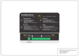
FIGURE 4: Repeater Label Placement
Unitary Controller Wiring
N
G
G
N
L
L
N
G
RELAY 1
RELAY 2
RELAY 3
RELAY 4
2
4
V
a
c
SPARE
SPARE
TOUCH
SCREEN
+24V
MS/TP
+
Gnd
SENSOR
A
B
C
D
S1
S2
MS/TP
-
OUTDOOR
SENSOR
ZONE 1
SENSOR
+12V
Rnet-
Rnet+
Gnd
ZONE 2
SENSOR
+12V
Rnet-
Rnet+
Gnd
ZONE 3
SENSOR
+12V
Rnet-
Rnet+
Gnd
ZONE 4
SENSOR
+12V
Rnet-
Rnet+
Gnd
N
N
L
L
24Vac
N1/Gnd
TRANSFORMER
N
N1
N1
2
4
V
ac
88F0
E143900
TYPE: 002003
Power
Off On
Power
Gnd
24Vac
Port 1
485
ARC-
Shield
Net -
Net +
156
Port 2a
Rnet
Gnd
Rnet +
Rnet -
+12V
Xnet +
Xnet -
Gnd
Xnet Expansion
Local
Rnet+
Gnd
Sense
+12V
Rnet-
Access
EIA-485
EIA-232
Thermistor/
dry-contact/
Mode Select
Universal Input
mA
RTD
Volts
10V Max, 20mA Max
Inputs: All
UI-4
UI-3
UI-2
UI-1
Gnd
+
Gnd
Gnd
+
+
Gnd
+
8
7
6
5
4
3
2
1
UI-8
Gnd
UI-6
UI-7
UI-5
Gnd
+
+
Gnd
+
Gnd
+
UI-12
UI-11
UI-10
UI-9
+
Gnd
+
Gnd
Gnd
+
Gnd
+
24 Vdc
24 Vdc
200mA maximum
Auto Off On
0-20mA
0-10Vdc
Relay
Controller
Address
1's
10's
Archive Valid
Port 2a Rx
Port 2a Tx
Port 1 Rx
Port 1 Tx
Battery low
Ext. Batt.
Int. Batt.
External
Battery
Gnd
+3V
Status
Module
3V Lithium Battery
CR-123A
0 = Download required
3 = Comm setup error
1 = Control Program Error
4 = System error
8 = Formatting
2 = RAM full
Chase = OK
Status Codes
Class 2
ONLY Use Copper
24Vac, 50VA
Without Keypad:
26Vdc, 23W, 0.9A
Outputs
24Vdc Max, 50mA Max
Format
Pot
2-wire
4-wire
2 wire4 wire
Rx -
Net-
Net+
n/c
Tx -
Tx +
Rx +n/c
EIA-232
DCD
Rx
Tx
DTR
Signal Ground
®
BACnet
Over ARCNET156 KBaud
Made in USA
Port 2a BT485
Port 1
Port 1 BT485
Conductors
2A, 50-60 Hz
Blinking Dot = 'Run'
On
Off
Enhanced
8
7
6
5
4
3
2
1
8
7
6
5
4
3
2
1
IP Addr
AssignedDefault
10/100 BaseT
Ethernet Port E1
100 LAN LINK
®
8
7
6
5
See BAS Table Below
Protocols
6
MS/TP m
MS/TP s
Off
N2 On
Lon SLTA
Off
BAUD
4
5
9600Off Off
19.2 KOff On
38.4 KOn Off
76.8 KOn On
On
Modbus
8
Off
Off
On
On
Off
4
BACnet
3
7
Off
On
Off
Off
Off
PTP Off
Off
On
Access Port 2a
Lon Option
Off
On
On
2
1
UO-1
UO-2
UO-3
UO-4
UO-8
UO-7
UO-6
UO-5
On
Off
2
1
BAS Port
BAS Port Settings
Set Pot Full CW
24Vac
DO NOT APPLY 24Vac TO
UNIVERSAL OUTPUTS
External 24Vdc relay coil only
Brownout
3
UO-2
UO-1
2
1
UO-4
UO-3
6
5
4
7
8
6
UO-7
UO-6
UO-5
3
1
2
4
5
UO-8
7
8
+
Gnd
+
Gnd
+
Gnd
+
Gnd
+
Gnd
+
Gnd
+
Gnd
+
Gnd
Aux Power Out
Port 2b
Port 2a
IOPro812u
07/10/12
Rev 6
Open Energy
Management Equipment
26Vdc
I/O Pro 812u
CONTROLLER
CB2
20A
11
14
12
COM
NO
NC
(A1)
(A2)
11
14
12
COM
NO
NC
(A1)
(A2)
11
14
12
COM
NO
NC
(A1)
(A2)
11
14
12
COM
NO
NC
(A1)
(A2)
TERMINAL BLOCK 1
+ -
Z1
Z2
Z3
Z4
CONNECTIONS INDICATED BY
(Optional)
Indicator Lights
BLK
WHT
GRN
L
120V 60HZ
1 20A
N
GND
ZONE 4
TO ADDITIONAL
BURNERS
L
N
G
CTH3
-
+
-
+
R
W
FIRE OUT
ANALOG IN
120VAC 60HZ
5A
L
N
G
CTH3
-
+
-
+
R
W
FIRE OUT
FIRE IN
120VAC 60HZ
5A
ZONE 3
L
N
G
CTH3
-
+
-
+
R
W
FIRE OUT
ANALOG IN
120VAC 60HZ
5A
L
N
G
CTH3
-
+
-
+
R
W
FIRE OUT
FIRE IN
120VAC 60HZ
5A
TO ADDITIONAL
BURNERS
ZONE 1
L
N
G
BURNER
ZONE 2
LOW VOLTAGE
THERMOSTAT
L
N
G
BURNER
LOW VOLTAGE
THERMOSTAT
TO ADDITIONAL
BURNERS
L
N
G
BURNER
LOW VOLTAGE
THERMOSTAT
L
N
G
BURNER
LOW VOLTAGE
THERMOSTAT
TO ADDITIONAL
BURNERS
P/N 91006114 Orig
REP 485
ON OFF
BT 485
CONNECTOR
ERTH GROUND
POWER
CONNECTOR
(NETWORK B)
(NETWORK B)
POWER
JUMPER
CONNECTOR
BT 485
CONNECTOR
(NETWORK A)
CONNECTOR
(NETWORK A)
LED1
LED2
24 Vac
LINE
LOAD
3
1
4
5
Shield
0.8 Amps. Fuse
To N ext Con tro lle r
1
2
Shield
2
1
3
2
1
1
2
3
LED3
120V 60HZ
24V 20VA
TRANSFORMER
Terminal Block
BASE PLATE
GREEN
BLACK
BLACK
WHITE
BLUE
YELLOW
From Central
Controller
Net -
Net +
Net-
Net+
120 Vac
HOT
NEUTRAL
GND
Satelaite 1
Satelaite 2
Repeater Wiring Diagram
GREEN

ROBERTS GORDON
®
CORAYVAC
®
MODULATING HEATING CONTROL CONTROLLER INSTALLATION MANUAL
6
FIGURE 5: Connected Components
BACnet
®
, Modbus
®
,
N2, or LonWorks
(requires separate LonWorks card)
RS 485 Wiring
(Central Controller)
(VFD(s) located inside
CORAYVAC
®
Modulating
Heating Control Enclosure)
RS 485 Wiring
BMS Operator’s Workstation
Outside Air Blower (optional)
Repeater
Outdoor Air Temperature Sensor
Vacuum
Pump
Indoor Sensor (one per zone)
CORAYVAC
®
Burners
(Zone 1)
Load Reactor
(as needed)
CORAYVAC
®
Burners
(Zone 2,
optional)

SECTION 1: INTRODUCTION
7
Connected Components (continued)
Indoor Sensor (one per zone)
RS 485 Wiring RS 485 Wiring
To Additional Controllers
(Maximum of 31 Satellite
Controllers per Central Controller)
(Satellite Controller)
CORAYVAC
®
Modulating Heating Control
(Satellite Controller)
COMPLETE™
Modulating Heating Control
Indoor Sensor (one per zone)
VANTAGE
®
CTH3
Modulating Heaters
VANTAGE
®
CTH2V
On/Off Heaters
NOTE: Any combination of CORAYVAC
®
,
VANTAGE
®
CTH2V or VANTAGE
®
CTH3/HEM heaters can be controlled from
a central and/or satellite controller. Diagram above only shows one possible combination.
If combining a CORAYVAC
®
system with VANTAGE
®
CTH3/HEM unitary heaters on a single CORAYVAC
®
Modulating
Heating Control, users are restricted to a maximum of 2 zones between and a single CORAYVAC
®
system and VANTAGE
®
CTH3/HEM unitary heaters.

ROBERTS GORDON
®
CORAYVAC
®
MODULATING HEATING CONTROL CONTROLLER INSTALLATION MANUAL
8
1.13 Carton Contents
100600XX: CORAYVAC
®
Modulating Heating Control Central Controller
10060XXX: CORAYVAC
®
Modulating Heating Control Satellite Controller
COMPLETE™ Modulating Heating Control
Installation Manual
(P/N 1006101NA)
CORAYVAC
®
Modulating
Heating Control Controller
with Modem Installed
Mounting Template
(P/N 91702810)
VFD Manual
CORAYVAC
®
Modulating
Heating Control Controller
with Modem Installed
Installation Manual
(P/N 1006101NA)
Mounting Template
(P/N 91702810)
VFD Manual
COMPLETE™ Modulating
Heating Control
Installation Manual
(P/N 1006101NA)
VFD Manual
Mounting Template
(P/N 91702810)

SECTION 1: INTRODUCTION
9
Accessories
Outdoor Sensor
(P/N 10081501)
Repeater (optional)
Supplied w/24 VAC
transformer inside
NEMA 1 enclosure
(P/N 10060156)
Indoor Sensor
(P/N 10061003)
Load Reactor
(P/N 10061019)
(P/N 10061020)
(P/N 10061021)
(P/N 10061022)
LonWorks Card
(P/N 10060160)
USB-L Cable
(P/N 10061017)
Terminating Resistor, BT485
(P/N 10061018)

ROBERTS GORDON
®
CORAYVAC
®
MODULATING HEATING CONTROL CONTROLLER INSTALLATION MANUAL
10
SECTION 2: SPECIFICATIONS
2.1 ROBERTS GORDON
®
CORAYVAC
®
Modulating Heating Control and COMPLETE™
Modulating Heating Control (Unitary Heaters)
2.1.1 Enclosures, Central and Satellite Controllers
Construction: 14 gauge painted steel, hinged
door, removable knockouts
provided.
Dimensions: W x H x D
CORAYVAC
®
Modulating Heating Control:
(in): 24.75 x 24.75 x 8.3
(cm): 16.8 x 20.75 x 8.2
COMPLETE™ Modulating Heating Control:
(in): 62.9 x 62.9 x 21.1
(cm): 41.7 x 52.7 x 20.8
Weight:
CORAYVAC
®
Modulating Heating Control:
70 lbs (31.7 Kg)
COMPLETE™ Modulating Heating Control:
(40 lbs (18.1 Kg)
2.1.2 Electrical
(Controller ONLY, VFD is powered separate of con-
troller, See Page 11, Section 2.7)
Power Supply: 120 V (+/- 10%) 1 Ø, 60 Hz, 20 Amps
UL Standard: 508A, UL Type 1
Universal Inputs:
Twelve Universal Inputs
0-5 Vdc
0-10 Vdc
0-20 mA
Thermister (10k ohm type II)
1K ohm RTD
Dry Contact
Universal Outputs:
0-10 Vdc
0-20 mA
Relay
HOA (hand/off/auto) switches for all outputs
Communication Ports:
Port 1: Configurable for ARC156 or EIA-485 (2-wire).
Built-in support for BACnet
(MS/TP or ARC156), N2, and Modbus
Port 2a: Configurable for EIA-232 or EIA-485 (2-wire
or 4-wire). Network protocol
selectable for BACnet (MS/TP or PTP), Modbus, N2,
LonWorks SLTA, or modem.
Port 2b: For LonWorks option Card.
Rnet port: Interface with a BACview5, BACview6, RS
sensors, or local laptop and Equipment Touch.
Battery: CR123A, 10 yr life, 720 cumulative hours of
power outage.
Note: Battery for time keeping purposes and saving
trend data during power outages.
Control Board Listed by: UL-916, CE, FCC Part 15-
Subpart B - Class A. BTL (BACnet Test Labs) - BAC-
net Building Controller (B-BC)
2.2 Terminating Resistor, BT485
(P/N 10061018)
Description: 1 plug-in terminating resistor, BT485
Operating Temperature Range: -29 to 60.0 °C; -20 to
140 °F
Overall dimensions: Width: 0.5 in, Height 0.6 in
2.3 Repeater
(P/N 10060156)
Enclosure: Fabricated in accordance with Non-
Metallic
UV-Rated
NEMA 3R
Dimensions: W x H x D
(in): 12 x 12 x 4
(cm): 30.5 x 30.5 x 10.5
Weight: 8 lbs (3.63 Kg)
Power: 24 Vac ±10%, 250 mA (6.0 VA), 50-60 Hz
Port: Net A and B are both EIA-485 (optically iso-
lated)
Power Supply: 120 V (+/- 10%) 1 Ø, 60 Hz, 0.8 Amps
Repeater Ports:
Net A and B are both EIA-485 (optically isolated)
Electronic board listed by, UL-916(PAZX)

SECTION 2: SPECIFICATIONS
11
CLU-916 (PAZX7) and CE
2.4 Load Reactor
(P/N 100610XX)
Load Reactor required on output side of VFD if total
wire length between VFD and vacuum pump is more
than 100' (30 m). Maximum length with load reactor
is 400' (121 m). For best performance, it is recom-
mended to mount load reactor as close to VFD as
possible. Load reactor protects the VFD from short
circuiting. Load reactors maximize pump perfor-
mance by improving voltage and current waveforms
from supply while also eliminating the possibility of
the pump overheating and noise emissions. Reactors
also minimize harmonic current levels within the drive
supply circuit.
Voltage: 460V/3Ø,2HP- 460V/3Ø,3/4 HP-230V/3Ø.
Frequency: 60Hz Fundamental Current Maximum.
Enclosure Dimension:
(in): 10 x 10 x 8.13
(cm): 25.4 x 25.4 x 20.65
IP: 20
2.5 Temperature Sensors
Indoor Sensor
(P/N 10061003)
Dimensions: W x H x D
(in): 4.75 x 3 x 0.75
(cm): 12.1 x 7.6 x 1.9
Power: 12 Vdc
Operating Temperature Range:
32 to 122 °F (0 to 50 °C)
Features: LCD temp display, setpoint display, set-
point adjustment, override button, information screen,
diagnostics screen
Outdoor Sensor
(P/N 10081501)
Dimensions: W x H x D
(in): 1.4 x 5.3 x 0.75
(cm): 3.6 x 13.5 x 1.9
Operating Temperature Range:
-40 to 221 °F (-40 to 105 °C)
Enclosure: NEMA 4 gasketed aluminum LB
housing, ½" threaded connection
2.6 Touchscreen (HMI) (Located on Central
Controller:
Dimensions: W x H x D
(in): 5.4 x 4.6 x 1.3
(cm): 13.7 x 11.7 x 3.3
Power: 24 Vac, 50-60 Hz
Operating temp range: -4 to 140 °F (-20 to 60 °C)
Features: 4.3" touchscreen color LCD display, temp
sensor, humidity sensor
2.7 Variable Frequency Drive (Located inside
CORAYVAC
®
Modulating Heating Control)
2.7.1 Electrical
Power Output: 230 V, 3 Ø, 0-60 Hz
(for 115 V and 230 V models)
460 V, 3 Ø, 0-60 Hz
(for 460 V models)
Speed Reference Follower: 0-10 Vdc or 4-20 mA
UL Standard: Industrial Controls Equipment
Ambient Operating Temp.:
32 - 104 °F (0 - 40 °C)
1 HP, 120V 1 Ø Drive (used with EP-203 pump)
(P/N 10061201)
Power Input: 115 V, 1 Ø, 50-60 Hz
Input Voltage Tolerance: +/- 10%
Amps: 4.3
1 HP, 208/230v 1 Ø Drive (used with EP-203 pump)
(P/N 10061202)
Power Input: 208/230 V, 1 Ø, 50-60 Hz
Input Voltage Tolerance: +/- 10%
Amps: 4.3
2 HP, 208/230V 1 Ø Drive (used with EP-303
pump)
(P/N 10061203)
Power Input: 208/230 V, 1 Ø, 50-60 Hz
Input Voltage Tolerance: +/- 10%
Amps: 7

ROBERTS GORDON
®
CORAYVAC
®
MODULATING HEATING CONTROL CONTROLLER INSTALLATION MANUAL
12
1 HP, 460V 3 Ø Drive (used with EP-203 pump)
(P/N 10061204)
Power Input: 460 V, 3 Ø, 50-60 Hz
Input Voltage Tolerance: +/- 10%
Amps: 2.2
2 HP, 460V 3 Ø Drive (used with EP-303 pump)
(P/N 10061205)
Power Input: 460 V, 3 Ø, 50-60 Hz
Input Voltage Tolerance: +/- 10%
Amps: 4.1
1 HP, 208/230V 3 Ø Drive (used with EP-203
pump)
(P/N 10061206)
Power Input: 208/230 V, 3 Ø, 50-60 Hz
Input Voltage Tolerance: +/- 10%
Amps: 4.3
2 HP, 208/230V 3 Ø Drive (used with EP-303
pump)
(P/N 10061207)
Power Input: 208/230 V, 3 Ø, 50-60 Hz
Input Voltage Tolerance: +/- 10%
Amps: 7

SECTION 3: INSTALLATION
13
SECTION 3: INSTALLATION
Installation of CORAYVAC
®
Modulating Heating Con-
trol and associated external electrical wiring must be
done by an electrician qualified in the installation of
control systems for heating equipment.
3.1 Preparation
Before installing controller, observe the following:
3.1.1 Ensure that you have a copy of the site layout
for the project that clearly identifies the separate
zones and wiring distances between all components.
3.1.2 Familiarize yourself with the Controller and Vari-
able Frequency Drive component names and loca-
tions. See Page 14, Figure 6, Figure 6.
Note: The VFD is located inside of the CORAYVAC
®
Modulating Heating Control panel. Be sure to plan
accordingly.
DANGER
Electrical Shock Hazard
Disconnect electric before service.
Controller must be properly grounded to an
electrical source.
Failure to follow these instructions can
result in death or electrical shock.

ROBERTS GORDON
®
CORAYVAC
®
MODULATING HEATING CONTROL CONTROLLER INSTALLATION MANUAL
14
FIGURE 6: ROBERTS GORDON
®
CORAYVAC
®
Modulating Heating Control Specifications
88F0
E143900
TYPE: 002003
Power
Off On
Power
Gnd
24Vac
Port 1
485
ARC-
Shield
Net -
Net +
156
Port 2a
Rnet
Gnd
Rnet +
Rnet -
+12V
Xnet +
Xnet -
Gnd
Xnet Expansion
Local
Rnet+
Gnd
Sense
+12V
Rnet-
Access
EIA-485
EIA-232
Thermistor/
dry-contact/
Mode Select
Universal Input
mA
RTD
Volts
10V Max, 20mA Max
Inputs: All
UI-4
UI-3
UI-2
UI-1
Gnd
+
Gnd
Gnd
+
+
Gnd
+
8
7
6
5
4
3
2
1
UI-8
Gnd
UI-6
UI-7
UI-5
Gnd
+
+
Gnd
+
Gnd
+
UI-12
UI-11
UI-10
UI-9
+
Gnd
+
Gnd
Gnd
+
Gnd
+
24 Vdc
24 Vdc
200mA maximum
Auto Off On
0-20mA
0-10Vdc
Relay
Controller
Address
1's
10's
Archive Valid
Port 2a Rx
Port 2a Tx
Port 1 Rx
Port 1 Tx
Battery low
Ext. Batt.
Int. Batt.
External
Battery
Gnd
+3V
Status
Module
3V Lithium Battery
CR-123A
0 = Download required
3 = Comm setup error
1 = Control Program Error
4 = System error
8 = Formatting
2 = RAM full
Chase = OK
Status Codes
Class 2
ONLY Use Copper
24Vac, 50VA
Without Keypad:
26Vdc, 23W, 0.9A
Outputs
24Vdc Max, 50mA Max
Format
Pot
2-wire
4-wire
2 wire 4 wire
Rx -
Net-
Net+
n/c
Tx -
Tx +
Rx +n/c
EIA-232
DCD
Rx
Tx
DTR
Signal Ground
®
BACnet
Over ARCNET156 KBaud
Made in USA
Port 2a BT485
Port 1
Port 1 BT485
Conductors
2A, 50-60 Hz
Blinking Dot = 'Run'
On
Off
Enhanced
8
7
6
5
4
3
2
1
8
7
6
5
4
3
2
1
IP Addr
Assigned Default
10/100 BaseT
Ethernet Port E1
100 LAN LINK
®
8
7
6
5
See BAS Table Below
Protocols
6
MS/TP m
MS/TP s
Off
N2 On
Lon SLTA
Off
BAUD
4
5
9600 Off Off
19.2 K Off On
38.4 K On Off
76.8 K On On
On
Modbus
8
Off
Off
On
On
Off
4
BACnet
3
7
Off
On
Off
Off
Off
PTP Off
Off
On
Access Port 2a
Lon Option
Off
On
On
2
1
UO-1
UO-2
UO-3
UO-4
UO-8
UO-7
UO-6
UO-5
On
Off
2
1
BAS Port
BAS Port Settings
Set Pot Full CW
24Vac
DO NOT APPLY 24Vac TO
UNIVERSAL OUTPUTS
External 24Vdc relay coil only
Brownout
3
UO-2
UO-1
2
1
UO-4
UO-3
6
5
4
7
8
6
UO-7
UO-6
UO-5
3
1
2
4
5
UO-8
7
8
+
Gnd
+
Gnd
+
Gnd
+
Gnd
+
Gnd
+
Gnd
+
Gnd
+
Gnd
Aux Power Out
Port 2b
Port 2a
IOPro812u
07/10/12
Rev 6
Open Energy
Management Equipment
26Vdc
Status LED's
Port Setup
Universal
Port 1
24 Vac Power in
BT485 Terminating Resistor Port
Power
Port 1Jumper
Port 2a
Rnet Port
(Sensors)
Port 2a
Jumpers
Jumpers
Universal
Inputs
Manual Switch for
VFD1 (Optional)
Manual Switch for
VFD2 (Optional)
Ethernet Port
Inputs
HOA
Switches
(Hand/Off/Auto)
Indicator Light
FOR outputs
Jumpers
Controller (MAC)
Address,RotarySwitches
DIP Switch
Battery

SECTION 3: INSTALLATION
15
3.2 Positioning CORAYVAC
®
Modulating Heating
Control
3.2.1 For serviceability, it is convenient to mount the
controller at occupant level in the vicinity of the
pump. For proper frequency between the VFD and
pump, the wire length between controller and vac-
uum pump should not be more than 100' (30 m). A
Load Reactor (P/N 100610XX) will be required for
distances greater than 100' (30 m). Maximum dis-
tance with Load Reactor is 400' (120 m). Load reac-
tor should be mounted as close to VFD as possible.
Consult factory if distance required is greater.
Do not mount controller outdoors. Controller must
not be installed where subjected to adverse condi-
tions such as: combustible, oily, or hazardous vapors
or dust; excessive moisture or dirt; vibration. To avoid
damage from possible condensation leaks, do not
mount controller directly beneath pump. Avoid install-
ing the controller in mezzanines, direct sunlight, or
near external heat sources because these locations
usually have unpredictable temperature rises.
FIGURE 7: Controller Mounting - CORAYVAC
®
Modulating Heating Control
(Dimensions shown in inches)
FIGURE 8: Controller Mounting - COMPLETE™
Modulating Heating Control
(Dimensions shown in inches)
Note: A paper mounting template is included with the
CORAYVAC
®
Modulating Heating Control and the
COMPLETE™ Modulating Heating Control panels.
Appropriately position the template on the mounting
surface, ensuring the template is level prior to mark-
ing each mounting hole shown on template. Pre-drill
mounting holes using a 9/32" drill bit. Position control
0.33
R0.16
R0.16
19.00
1.5 TYP.
1.5 TYP
1.5 TYP.
19.00
0.51
R0.27
R0.16
21.36
0.51
1.50
0.33
R0.16
R0.16
1.5 TYP
1.5 TYP.
0.51
R0.27
R0.16
0.51
1.50
17.88
11.00
11.00
17.88
R0.16
R0.27

ROBERTS GORDON
®
CORAYVAC
®
MODULATING HEATING CONTROL CONTROLLER INSTALLATION MANUAL
16
panel over pre-drilled holes and secure control panel
using minimum 5/16" - 18 x 2" bolts and washers (not
supplied).
3.3 Cable Requirements:
As per individual building specification for class of
cable to be used. Use copper conductors only. Below
is the recommended cable for the various connec-
tions for CORAYVAC
®
and COMPLETE™ Modulat-
ing Heating Control.
CAUTION:
• Separate line and low voltage circuits.
• Do not run line voltage wiring through bottom
section of enclosure that houses control
board.
• Do not run low voltage through top section of
enclosure that houses the relay board.
• Do not run line and low voltage wiring in same
conduit.
• Do not run wiring for vacuum pumps 1 and 2
from VFDs in the same conduit.
Note:
Avoid running communication wires or sensor input
wires next to AC power wires or the controller's relay
output wires. The resulting noise can affect signal
quality. Common sources of noise are:
• Spark igniters
• Radio transmitters
• Variable speed drives
• Electric motors (> 1hp)
• Generators
• Relays
• Transformers
• Induction heaters
• Large contactors (i.e., motor starters)
• Video display devices
• Lamp dimmers
• Fluorescent lights
3.4 CORAYVAC
®
and COMPLETE™ Modulating
Heating Control Installation Materials
Note: Systems must be electrically grounded in
accordance with the following codes: United States:
Refer to National Electrical Code®, NFPA 70 - latest
revision. Wiring must conform to the most current
National Electrical Code®, local ordinances and any
special diagrams furnished.
Canada: Refer to Canadian Electrical Code, CSA
C22.1 Part 1 - latest revision. Plan accordingly.
3.4.1 Switchable Loads
The controller relays are rated for switching loads no
greater than 6 A. The total added current load for all
4 relays must not exceed 20 A.
3.4.2 Control Programming Details
Controllers are pre-programmed. Can be configured
in the field to any combination of one/two pumps,
four heating zones, single stage or modulating uni-
tary heaters, CORAYVAC
®
or VANTAGE
®
Multiburner
systems.
• Control Power Supply Connection
The power connection should be made with cable,
size 12 AWG.
• Four Digital Output (Relays)
The control connection for load of each individual
relay should be made with cable, size 14 AWG.
• Modulation Signal from Control Board (UO 5-8)
0-10V control signal from outputs UO 5-8 on the
modulation controller to modulating heaters, should
be made with cable, size 18 AWG.
• Digital Input
The wiring connection for the pressure switch should
be unshielded cable, size 18 AWG.
• Indoor Sensor Cable
Rnet communication wires should be connected in a
daisy-chain or hybrid configuration. For star configu-
ration, contact factory. See examples on Page 17,
Figure 9 through Page 18, Figure 10.
Note: Use the specified type of wire and cable for
maximum signal integrity.
Description
4 conductor, shielded, CMP, plenum
rated cable
Conductor 22 AWG (7x0096) bare copper
Max Length 500’ (152 m)
Insulation Low-smoke PVC (or equivalent)
Color Code Black, white, green, red
Shielding If shielded, Aluminum/Mylar shield
(100% coverage) with TC drain
wire
UL Temperature
Rating
32-167°F (0-75°C)
Voltage 300 Vac, power limited
Listing UL: NEC CL2P, or better
/