Page is loading ...

1
Heimsport-Trainingsgerät
Ergometer
AL 4
Montage- und Bedienungsanleitung
für Bestell-Nr. 1611
Notice de montage et d’utilisation du
No. de commande 1611
Assembly and exercise instructions
for Order No. 1611
Montage- en bedieningshandleiding voor
Bestellnummer 1611
GBD
F NL
RU
Инструкция по монтажу и эксплуатации
№ заказа 1611

3
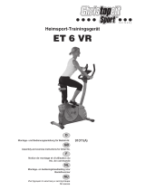
Montageübersicht:
Assembly overview:
Aperçu de l‘Assemblée:
Montage overzicht:
Обзор Ассамблея:
D
GB
F
NL
RU

16
Important Recommendations and
Safety Instructions
Our products are all tested and therefore represent the highest current safety
standards. However, this fact does not make it unnecessary to observe the
following principles strictly.
1. Assembly the machine exactly as described in the installation instructions
and use only the enclosed, specific parts of the machine. Before assembling,
verify the completeness of the delivery against the delivery notice and the
completeness of the carton against the assembly steps in the installation
and operating instructions.
2. Before the first use and at regular intervals (approximately every 50 Operat-
ing hours) check the tightness of all screws, nuts and other connections and
the access shafts and joints with some lubricant so that the safe operating
condition of the equipment is ensured. In particular, the adjustment of saddle
and handlebar need smooth function and good condition.
3. Set up the machine in a dry, level place and protect it from moisture and
water. Uneven parts of the floor must be compensated by suitable measures
and by the provided adjustable parts of the machine if such are installed.
Ensure that no contact occurs with moisture or water.
4. Place a suitable base (e.g. rubber mat, wooden board etc.) beneath the
machine if the area of the machine must be specially protected against
indentations, dirt etc.
5. Before beginning training, remove all objects within a radius of 2 metres
from the machine.
6. Do not use aggressive cleaning agents to clean the machine and employ
only the supplied tools or suitable tools of your own to assemble the machine
and for any necessary repairs. Remove drops of sweat from the machine
immediately after finishing training.
7. WARNING! Systems of the heart frequency supervision can be inexact.
Excessive training can lead to serious health damage or to the death. Consult
a doctor before beginning a planned training programme. He can define
the maximum exertion (pulse, Watts, duration of training etc.) to which you
may expose yourself and can give you precise information on the correct
posture during training, the targets of your training and your diet. Never
train after eating large meals.
8. Only train on the machine when it is in correct working order. Use original
spare parts only for any necessary repairs. WARNING! Replace the worm
parts immediately and keep this equipment out of use until repaired.
9. When setting the adjustable parts, observe the correct position and the
marked, maximum setting positions and ensure that the newly adjusted
position is correctly secured.
10. Unless otherwise described in the instructions, the machine must only
be used for training by one person at a time. The exercise time should not
overtake 60 min./daily.
11. Wear training clothes and shoes which are suitable for fitness training
with the machine. Your clothes must be such that they cannot catch dur-
ing training due to their shape (e.g. length). Your training shoes should be
appropriate for the trainer, must support your feet firmly and must have
non-slip soles.
12. WARNING! If you notice a feeling of dizziness, sickness, chest pain or
other abnormal symptoms, stop training and consult a doctor.
13. PNever forget that sports machines are not toys. This appliance can be
used by children aged from 8 years and above and persons with reduced
physical, sensory or mental capabilities or lack of experience and knowl-
edge if they have been given supervision or instruction concerning use of
the appliance in a safe way and
understand the hazards involved. Children shall not play with the appli-
ance. Cleaning and user maintenance shall not make by children without
supervision. Take suitable measures to ensure that children never use the
machine without supervision.
14. The appliance use only to be used with the power supply unit provided
with the appliance.
15. Ensure that the person conducting training and other people never move
or hold any parts of their body into the vicinity of moving parts.
16. At the end of its life span this product is not allowed to dispose over
the normal household waste, but it must be given to an assembly point for
the recycling of electric and electronic components. You may find the symbol
on the product, on the instructions or on the packing.
The materials are reusable in accordance with their marking. With the re-use,
the material utilization or the protection of our environment. Please ask the
local administration for the responsible disposal place.
17. To protect the environment, do not dispose of the packaging materials,
used batteries or parts of the machine as household waste. Put these in
the appropriate collection bins or bring them to a suitable collection point.
18. For speed dependent operation mode, the braking resistance level can
be adjustable manually and the variations of power will depend on the ped-
aling speed. For speed independent operation mode, the user can set the
wanted power consumption level in Watt, constant power level will be kept
by various braking resistance levels, that will be determined automatically
by system. That is independent on the pedaling speed.
19. The machine is equipped with 32-step resistance adjustment. This makes
it possible to reduce or increase the braking resistance and thereby the
training exertion. Pressing the button “-” for the resistance setting towards
stage 1 reduces the braking resistance and thereby the training exertion.
Pressing the button “+” for the resistance setting towards stage 24 increases
the braking resistance and thereby the training exertion.
20. This machine has been tested and certified in compliance with DIN EN
ISO 20957-1/2014 and EN 957-5/2009 “H,A”. The maximum permissible
load (=body weight) is specified as 150 kg. The classification of HA means
this exercise bike is designed foe home use only and with good accuracy
class, the variations of power consuming are within ±5W up to 50W and
±10% over 50W. This item’s computer corresponds to the basic demands
of the EMC Directive of 2014/30/EU.
Contents
1. Summary of Parts Page 3
2. Important Recommendations and Safety Information Page 16
3. Parts List-List of spare parts-tec. Data Page 17 - 19
4. Assembly Instructions With Exploded Diagrams Page 20 - 23
Mount, use and dismount
5. Watt table Page 24
6. Computer instructions-trouble shooting Page 25 - 27
Cleaning, Check and Storage
7. Training Instructions, Warm-up Page 28
Dear customer,
We congratulate you on your purchase of this home training sports unit and
hope that we will have a great deal of pleasure with it. Please take heed
of the enclosed notes and instructions and follow them closely concerning
assembly and use.
Please do not hesitate to contact us at any time if you should have any
questions.
Top-Sports Gilles GmbH
Friedrichstr. 55
42551 Velbert
GB

17
English
Please contact us if any components are defective or missing, or if
you need any spare parts or replacements in future:
Adress: Top-Sports Gilles GmbH
Friedrichstr. 55
42551 Velbert
Telefon: +49 (0) 20 51 - 6 06 70
Telefax: +49 (0) 20 51 - 6 06 74 4
e-mail: [email protected]
www.christopeit-sport.com
Parts List – Spare Parts List
AL 4 Order No. 1611
Technical data: Issue: 01. 04. 2016
Ergometer of Class HA with high accuracy
Combination of hometrainer and nordic walking.
Exercise your endurance and legs as well your arms
in a comfortable upright position.
• 32 –stepped Motor- and Computer-controlled magnetic resistance (Magne-
tic-Brake-System)
• Approx. 8 kg flywheel mass
• 12 stored training programs
• 4 heart rate programs with default of the maximum pulse rate (pulse guided)
• 4 individual programs
• 1 manual program
• 1 speed independent program (Default of wattage from 10 – 350 watt steps,
resistance adjustable in 5-watt steps)
• Hand pulse measurement
• Horizontally and vertically adjustable comfort saddle
• Floor level compensation
• Transport rollers
• Power plug (Adapter)
• Back light LCD display, 7 window display with simultaneous display of:
Time, Speed, Distance,
Illustration Designation Dimensions Quantity Attached to ET number
No. mm illustration No.
1 Computer 1 92 36-1611-03-BT
2 Screw M5x10 4 1+92 39-9903
3 Cable plug 12 3 6+92 36-9134-22-BT
4 Nylon bushing 19x38 6 16+92 36-9825328-BT
5 Washer 19//38.5 2 93 36-9925114-BT
6L Hand grip left 1 16L 33-1611-05-WS
6R Hand grip right 1 16R 33-1611-06-WS
7 Screw M4x25 2 10 36-9111-38-BT
8 End cap 2 6 36-1611-07-BT
9 Hand wrapping 2 6 36-1611-08- BT
10 Hand pulse sensor 2 6 36-9126-06-BT
11 Pulse cable 2 6 36-1611-09-BT
12 Pulse connection cable 2 1+11 36-1611-10-BT
13 Allen bolt M8x20 2 93 39-9886-CR
14 Spring washer for M8 14 13,56+99 39-9864-VC
15 Washer 8//36 2 13 39-10166
16L Connection tube left 1 6L+31 33-1611-07-WS
16R Connection tube right 1 6R+31 33-1611-08-WS
17 Self-tapping screw 4.5x25 13 16+46 36-9825338-BT
18L-1 Front plastic cover left 1 16L+18L-2 36-1611-11-BT
18L-2 Rear plastic cover left 1 16L+18L-1 36-1611-12-BT
18R-1 Front plastic cover right 1 16R+18L-2 36-1611-13-BT
18R-2 Rear plastic cover right 1 16R+18R-1 36-1611-14-BT
19 Connection cable 1 1+94 36-1507-15-BT
20 Seat 1 22 36-9806210-BT
21 Square plug 38x38 2 22 36-9211-23-BT
22 Seat slide 1 20+22 33-9211-07-WS
23 Fixed bracket 1 22 33-9211-08-SI
24 Washer 10//25 1 23 39-9989-CR
25 Hand grip nut M10 1 23 36-9211-19-BT
26 Seat support 1 22+57 33-1611-09-WS
27 Plastic slide 1 57 36-9211-40-BT
28 Quick release M16 1 57 36-9613220-BT
29 Nylon Nut M8 2 16 39-9918-CR
30 Washer 8//24 2 29 39-9844-CR
31 Connecting bar 2 16+42 33-1611-10-WS
32 Bushing 10x22 2 31 36-1611-15-BT
33 Plastic Washer 10//22 2 16 36-1611-16-BT
34 Washer 10//19 2 16 39-9989-CR
approx. Calorie consumption, RPM, Watt and Pulse frequency
• Input of individual limits: Time, Distance, approx. Calorie consumption, Pulse
frequency and Watt
• Announcement when limits are exceeded
• Body fat analysis (BMI)
• Load max. 150 kg (body weight)
Space requirement approx.: L 101 x W 64 x H 137 cm
Items weight: 33kg
Exercise space approx: min. 2,5m²

18
Illustration Designation Dimensions Quantity Attached to ET number
No. mm illustration No.
35L Pedal left 1 42L 36-1611-04-BT
35R Pedal right 1 42R 36-1611-05-BT
36 Washer 15//31 2 35 36-1611-29-BT
37 Plastic Washer 15//31 4 35 36-1611-30-BT
38 Bushing 15x31 2 31 36-1611-31-BT
39 Washer 13//31 2 35 39-10062-CR
40 Crank cap 2 35 36-9840-15-BT
41 Hex screw 2 35 39-9886-CR
42L Crank left 1 35L+82 33-1611-11-SW
42R Crank right 1 35R+82 33-1611-12-SW
43L Nylon nut left 1 35L 36-9111-19-BT
43R Nylon nut right 1 35R 36-9111-20-BT
44 Plastic screw 1 46 36-1611-17-BT
45 Rear plastic cover 1 46 36-1611-06-BT
46L Chain cover left 1 46R+57 36-1611-01-BT
46R Chain cover right 1 46L+57 36-1611-02-BT
47 Drill screw M5x15 11 46+57 39-9907
48 Safety clip C17 2 82 36-9825320-BT
49 Washer 17//22 2 82 39-10135
50 Bearing 6003-2RS 2 57+82 36-9806214-BT
51 Allen bolt M6x15 1 53 39-9860
52 Washer 6//14 1 51 39-9863
53 Idler wheel 24x37x20.5 1 57 36-9806216-BT
54 Wave washer 10//15 3 53 36-1508-11-BT
55 Axle nut M10x1.25 1 64 39-9820-SW
56 Allen bolt M8x20 8 16,57+92 39-9886-CR
57 Main Frame 1 33-1611-01-WS
58L Rear stabilizer cap left 1 59 36-1611-18-BT
58R Rear stabilizer cap right 1 59 36-1611-19-BT
59 Rear stabilizer 1 57 33-1611-04-WS
60 Axle nut small M10x1.25 2 64 39-9820
61 Safety clip C10 2 64 36-1611-20-BT
62 Bearing 6000-2RS 2 63 36-1611-21-BT
63 Flywheel 1 61+62 33-1611-13-SI
64 Flywheel axle 1 57+63 36-1611-25-BT
65 Chain adjuster set 2 57+63 39-10172
66 Axle nut 1 64 39-9820
67 Axis protection cap 2 55+66 36-1123-28-BT
68 Allen bolt M6x15 2 71 39-9911
69 Spring washer for M6 2 68 39-9865-SW
70 Washer 6//14 3 68 39-9863
71 Axle magnet bracket M6x14 1 72 36-9225-11-BT
72 Magnet bracket 1 57 33-1611-14-SI
73 Magnet 1 81 36-9825506-BT
74 Nylon nut M6 1 75 39-9816-VC
75 Double-thread screw 1 72 36-1611-22-BT
76 Spring 1 72 36-1611-23-BT
77 Nut M6 2 72 39-9861-VZ
78 Sensor cable 1 57 36-1507-05-BT
79 Washer 17//22 2 82 39-10135
80 Wave washer 17//22 1 82 36-9918-22-BT
81 Belt wheel 1 82 36-1611-24-BT
82 Pedal axle 1 50+81 33-1105-07-SI
83 Screw M8x12 3 81+82 39-9886-CR
84 Belt 360J6 1 63+81 36-1104-07-BT
85L Front stabilizer cap left 1 86 36-1611-26-BT
85R Front stabilizer cap right 1 86 36-1611-27-BT
86 Front stabilizer 1 57 33-1611-03-WS
87 Washer 8//19 4 99 39-9917-CR

19
English
Illustration Designation Dimensions Quantity Attached to ET number
No. mm illustration No.
88 Connection wire 1 72+96 36-1507-09-BT
89 Handlebar post cover 1 92 36-1611-28-BT
90 Rubber ring 1 89 36-1611-32-BT
91 Curved Washer 8//19 8 56 39-9966-CR
92 Handle bar post 1 57 33-1611-02-WS
93 Handgrip axle 1 16+92 33-1611-15-SI
94 Motor cable 1 19+96 36-1507-14-BT
95 Drill screw M5x10 4 96 39-9907
96 Motor 1 57+94 36-1507-07-BT
97 DC cable 1 16L+98 36-1507-08-BT
98 Adapter 9Volt=DC/500mA 1 97 36-1507-22-BT
99 Allen bolt M8x25 4 59,57+86 39-10455
100 Combination wrench 1 36-9107-27-BT
101 Open end wrench 1 36-1611-33-BT
102 Allen key wrench 2 36-9107-28-BT
103 Assembly and exercise instruction 1 36-1611-34-BT

20
Assembly Instructions
Remove all the separate parts from the packaging, lay them on the floor
and check roughly that all are there on the base of the assembly steps.
Please note that a number of parts are connected directly to the main
frame preassembled. In addition, there are several other individual parts
that have been attached to separate units. This will makes assembly
easier and quicker for you. Assembly time: 40 - 50 min.
Step 1:
Attach the stabilizer (59+86) at main frame (57).
1. Attach the front foot (86) with preassembled transportation roller (85) to
the main frame (57). Do this with screws M8x25 (99), washers (87) and
spring washers (14).
2. Attach the rear foot (59) with preassembled height adjustable caps (58)
to the main frame (57). Do this with screws M8x25 (99), washers (87)
and spring washers (14). After assembly has been complete, you can
compensate for minor irregularities in the floor by turning the wheel at
foot caps (58). The equipment should be set up that the equipment does
not move of its own accord during a training session.
Step 2:
Connection of cables (19+94) and assembly of support (92) at the main
frame (57).
1. Place screws M8x20 (56), curved washers (91) and spring washers (14)
accessibly beside the front part of the main frame (57).
2. Place the lower end of the support (92) against the main frame (57) and
push the support cover (89) with rubber ring (90) onto the support (92).
Plug the ends of the two computer cable harnesses (19+94) projecting
from (57+92) together.
(Note: The computer cable harness (19) projecting from the support (92)
must not slide into the tube, as it is required for later steps of installa-
tion.) When joining the tubes, ensure that the cable connection will not
trapped.
3. Put one spring washer (14) and one curved washer (91) on each screw
(56). Push the screws (56) through the holes in the support (92), screw
into the threaded holes of the main frame (57) and tighten lightly. (This
screw connection point will screw firmly at least in Step 4.)
Step 3:
Installation of the handgrips (6) with connecting tubes (16) at support
(92).
1. Push the axle (93) into the middle position at handlebar support (92) and
put one wave washer (5) and the connecting tube right (16R) onto the
right axles’ end (93). Put on the screw M8x20 (13) a spring washer (14)
and a big washer 8//38 (15) and tighten it firmly. (Note: Right is specified
as viewed standing on the machine during training.)
2. Install the left connection tube (16L) incl. all additionally required parts
on the left hand side of the machine as described in 1.
3. Push the hand grips (6L+6R) onto the connecting tubes (16L+16R) and
adjust the holes in the tubes so that they are aligned.
(Note: the handgrip bars must be aligned after assembly so that the
upper ends are inclined outwards (away from the support (92)).
4. Push the bolt M8x20 (56) through the holes and tighten the handgrip
bars (6) with curved washers (91) and spring washers (14) at connection
tubes (16L+16R) firmly.
5. Connect the pulse connection cables (12) with pulse cables (11).

21
English
Step 4:
Attach the pedals (35L+35R) and connecting bars (31).
1. Put onto the right pedal (35R) one big washer 15//31 (36) and one big
plastic washer 15//31 (37) and then put it through the bushing 15//31
(38) and connecting bar (31) with right direction. Then slide again one
big plastic washer (37) and a washer 13//31 (39) onto it and screw into
the right pedal crank (42R) at the right-hand side. (as seen in operation.)
(Warning! the screw direction is clockwise).
2. Screw the left pedal (35L) with all necessary parts same way as describe
in Pos.1 into the left pedal crank (42R) at the left-hand side (as seen in
operation.) (Warning! the screw direction is anti-clockwise).
3. Then mount the pedal straps left and right on the associated pedals
(35). (The pedals are sign with “L” for Left and “R” for Right.)
4. Put onto the threat ends of connection tubes (16) one washer 10//19
(34) and one small plastic washer 10//22 (33) and the connecting bar
(31) with small bushing (32). Secure the position of connecting bar (31)
with washer 8//24 (30) and self-locking nut M8 (29).
Step 5:
Attach the saddle (20) and saddle support (26).
1. Push the saddle (20) with saddle bracket into the saddle slide (22) and
tight it up in desired position.
2. Place the saddle slide (22) into the holder of saddle support (26), set
it at the desired position and screw it onto the saddle support (26) by
screw (23) washer (24) and star grip nut (25).
3. Push the saddle support tube (26) into the matching locator in the main
frame (57), set it at the desired position and lock it by inserting the bolt
with the quick release (28) in place and doing it up tight.
(The setting of the saddle support can adjust easily as desired later
through turning and pulling the quick release (28).) Furthermore, you
must ensure when setting this desired position that the saddle support
is not pulled out of the main frame further than the highest setting posi-
tion, which is marked.
Attention: Ensure before every exercising that the saddle is tighten
firmly
5. Mount the left cover set (18L-1+18L-2) to left connection tube (16L) and
secure with screws (17).
6. Install the right handgrip cover set (18R-1+18R-2) to the right connection
tube (16R) and secure with screws (17).
7. Now turn the construction by hand 3-4 times and tighten the screws of
support (92) to main frame (57) as mentioned in Step 2 firmly. Push the
support cover (89) into right position.

22
Step 8:
Checks
1. Check the correct installation and function of all screwed and plug
connections.
Installation is thereby complete.
2. When everything is in order, familiarise yourself with the machine at a
low resistance setting and make your individual adjustments.
Note:
Please keep the tool set and the instructions in a safe place as these may
be required for repairs or spare parts orders becoming necessary later.
Step 7:
Attach the AC adaptor (98).
1. Please insert the plug of adaptor (98) to the power plug (97) at end of
chain cover.
2. Please insert the plug of adaptor (98) to the jack of wall power
(230V~50Hz).
Step 6:
Attach the computer (1) at support (92).
1. Put the plug of connection cable (19) into the plug from computer (1)
backside.
2. Insert the plug of pulse connection cables (12) to the jack of the computer
(1) and attach the computer (1) to top monitor bracket of front post (92)
with screws (2) which you find on backside of computer. (Attention:
Ensure that the cable loom are not crunched or pinched during instal-
lation.)

23
Mount, Use & Dismount
Transportation of Equipment:
There are two rollers equipped on the front foot. For moving, you can lift
up the rear foot and drive it to where you would like to locate or store it.
Adjustment – Seat Position
For an effective workout, the seat must be adjusted properly. While your
are pedaling, your Knees should be slightly bent when the pedals are in the
farthest position. In order to adjust the seat, unscrew the knob few turns
and draw it out slightly. Adjust the seat to the right height, then release the
knob and tighten it all the way.
Important:
Make sure to put the knob back into place in the seat post and tighten it
completely. Never exceed the maximum height of the seat. Always get off
the bicycle before making any adjustment.
A biomechanically optimal seating position ensures optimum power trans-
mission. The aim is that the existing force as large as possible arrives on the
pedals and the muscles with optimal effect works. The seat position affects
which muscles are in use primarily in essence. The right handlebar position
is responsible for keeping the upper body portion. Is the handlebar settings
chosen horizontally so you get an athletic posture. With each further step
towards the body, you adjust a more relaxed attitude. To adjust the hand-
lebar, simply loosen the screw handlebar until the handlebar can brought
into the desired position and tighten them after adjustment again firmly.
To avoid any problems such as back- / knee pain or numbness in the feet
through bad seat position on the bike, the maintenance of a proper adjust-
ment of the saddle and handlebar we strongly recommend.
Mount, Use & Dismount
Mount:
a. After the seat is adjusted to properly position, insert your foot into
retaining strap of pedal step on the pedal and hold
the handlebar tightly.
b. Try to put whole body weight on your foot and simultaneously cross
over the trainer and land your another foot on the other side.
c. Now you are in the position to start your training.
Use:
a. Keep you hands on the handlebar, and both feet are insert into retaining
straps of both pedal properly.
b. Pedal your exercise bike by your both feet alternately.
c. Then you can increase the pedaling speed gradually and adjust braking
resistance levels to increase the exercise intension.
Dismount:
a. Slow down the pedaling speed until it comes to rest.
b. Keep the left hand grabbing the left handlebar tightly, put your feet
cross over the equipment and land on the floor, then
land the other one.
Note:
This training equipment is a stationary exercise machine used to simulate
without causing excessive pressure to the joints, hence decreasing the risk
of impact injuries.
Exercise bike offer a non-impact cardiovascular workout that can vary from
light to high intensity based on the resistance preference set by the user.
It will strengthen your muscles of legs and increase cardio capacity and
maintain fitness of your body also.
English

24
RPM and Power in Watt of Level 1 - Level 32 for AL 4 Art.-Nr. 1611
Remarks:
1. The power consumptions (Watt) are calibrated by measuring the driving speed (min-1) of axle and the braking torque (Nm).
2. Your equipment was calibrated to fulfill the requirements of its accuracy classification before shipment, If you have doubts about the accuracy, please
contact with your local retailer or send it to accredited test laboratory to ensure or calibrate it.
(Please note that a deviation tolerance as noted on page 16, is permissible.)
LEVEL 30 RPM WATT 40 RPM WATT 50 RPM WATT 60 RPM WATT 70 RPM WATT
1 16 25 35 48 62
2 18 28 40 55 71
3 20 32 45 62 80
4 22 35 51 69 89
5 24 39 56 76 98
6 26 42 61 83 107
7 28 46 66 89 115
8 30 49 71 96 124
9 32 53 77 103 133
10 34 56 82 110 142
11 36 60 87 117 151
12 38 63 92 124 160
13 40 66 97 131 169
14 42 70 102 138 178
15 44 73 108 145 187
16 46 77 113 152 196
17 48 80 118 158 204
18 50 84 123 165 213
19 52 87 128 172 222
20 54 91 134 179 231
21 56 94 139 186 240
22 58 97 144 193 249
23 60 101 149 200 258
24 62 104 154 207 267
25 64 108 160 214 276
26 66 111 165 221 285
27 68 115 170 227 293
28 70 118 175 234 302
29 72 122 180 241 311
30 74 125 186 248 320
31 76 129 191 255 329
32 78 132 196 262 338

25
English
Trainingscomputer
DISPLAYS:
RPM = Rotation per minute: 0~999
(Change all 6 sec. with SPEED (km/h) display)
SPEED (Km/h) = Speed: 0.0~99.9 km/h (Change all 6 sec. with RPM dis-
play)
TIME =Workout time: 00:00~99:59.
DISTANCE (Km) = Distance: 0.0~99.99 km
CALORIES = burned calories: 0~9999kcal
WATT = Power consumption (Range of:10~350) (Change all 25sec. with
Load display)
Load = Resistance level:1~32 Levels
(Change all 25sec. with WATT display)
Pulse: bpm display P30~230 Heart symbol flash when use hand pulse
PROGRAM = Program selection 1-12programs
Program displays:
MANUAL = Manual mode workout
PROGRAM = Exercise programs P1-P12
USER = User creates resistance level profile
H.R.C. =target HR training mode 55%, 75%, 90% and TAG (target pulse)
WATT = constant training mode
KEYS:
1. F and +/- key: Function select and confirmation key.
User press / hold „F“ key 2 SECS, return to
original setting mold, let user to set up User data
(U1-U4, sex, age, height, weight) and Function value
(setting TIME / DISTANCE / CALORIES/PULSE / WATT)
+/- key : Increase and decrease or select option.
2. START/STOP -key: Start or Stop the program
3. RESET (L) -key: Reverse to main menu during presetting workout value
or stop mode. Hold on pressing for 2 sec. Computer will reboot and start
from user setting.
4. RECOVERY (Test) -key: test the heart rate recovery status.
5. BODY FAT -key: test body fat% and BMI in regard to user setting.
OPERATION
POWER ON:
Exercising without enter data:
1. Plug in power supply, computer will power on and display show all seg-
ments on LCD for 2 sec..
and then LCD display show user choice:
No need choose user and start exercising directly through pressing START/
STOP-key. With UP/DOWN (+/-) -turnkey you can adjust the resistance
level. All exercise data will show on display. You are in manual program.
Exercising with enter data:
1. Plug in power supply, computer will power on and display show all seg-
ments on LCD for 2 sec. then LCD display flash user (U1-U4). Select user
by turning UP/DOWN (+/-) -turnkey. Confirm setting by pressing MODE
(F) –key:
2. Put in individual user data gender (SEX - Male/Female) / Age / Height
and Weight through turning UP/DOWN (+/-) –turnkey and confirm setting
by pressing Mode (F) –key.
3. After presetting user, LCD display show program choice. You can select
1 of 5 program modes (MANUAL / PROGRAM / USER / HRC / WATT) by
turning UP/DOWN (+/-) –turnkey and confirm setting by pressing MODE
(F) – key. Press MODE (F) –key again for enter presetting TIME. You can
adjust with UP/DOWN (+/-) –turnkey, but you need not. All settings has to
confirm by pressing MODE (F) -key. Presetting will count down in function
TIME, DISTANCE and CALORIES. If there exists no presetting, the function
will count up.
4. If the program and presetting’s done press START/STOP –key to start
the exercise.
5. Pressing START/STOP –key again stops the program.
In General:
1. If user stop cycling within 4 min. you can continuous the program by
pressing START/STOP –key again. After 4 min. without any key function
the computer switched off to power save mode
2. The display which flashes is adjustable
3. The exercise profile is divided into 20 columns but at display are shown
only the first 8 columns. If exercise program reached the 9th column, the
display columns follow the exercise profile till last column.
4. If the computer act abnormal please plug out the AC adapter and plug
in again
5. Keep moisture away from computer.
6. Only use a suitable AC adapter with Output data of 9 Volt=DC/500mA.

26
Program Mode:
After presetting user 1-4, LCD display show program choice. You can se-
lect 1 of 5 program modes (MANUAL / PROGRAM / USER / HRC / WATT)
by turning UP/DOWN (+/-) –turnkey and confirm setting by pressing MODE
(F) –key.
Manual Mode:
Press START/STOP –key in main menu may start workout in manual mode.
1. Turn UP/DOWN (+/-) –turnkey to select workout program, choose Ma-
nual and press MODE (F) –key to enter.
2. Turn UP/DOWN (+/-) –turnkey to preset TIME, DISTANCE, CALORIES
and PULSE and press MODE (F) –key to confirm.
3. Press START/STOP –key to start workout.
4. During workout, user can turn UP/DOWN (+/-) –turnkey to adjust load
level from 1 to 32 levels.
5. Press START/STOP –key to break workout. Press RESET (L) -key to
reverse to main menu.
Program Mode P1-P12:
1. Turn UP/DOWN (+/-) –turnkey to select workout program, choose PRO-
GRAM with 12 files and press MODE (F) -key to enter.
2. Turn UP/DOWN (+/-) –turnkey to preset workout TIME.
3. Press START/STOP –key to start workout.
4. During workout, user can turn UP/DOWN (+/-) –turnkey to adjust load
level.
5. Press START/STOP –key to break workout. Press RESET (L) –key to
reverse to main menu.
User Program mode
1. Turn UP/DOWN (+/-) –turnkey to select workout program, choose User
program and press MODE (F) -key to enter.
2. Turn UP/DOWN (+/-) –turnkey to set load level of each column, and
press MODE (F) -key to confirm and get next one. (Total column = 20)
3. Hold on pressing MODE (F) -key for 2sec. to finish or quit setting.
4. Turn UP/DOWN (+/-) –turnkey to preset workout TIME.
5. Press START/STOP –key to start workout.
6. Press START/STOP –key to break workout. Press RESET (L) –key to
reverse to main menu.
7. During workout, user can turn UP/DOWN (+/-) –turnkey to adjust load
level from 1 to 32 levels.
H.R.C. mode:
1. Turn UP/DOWN (+/-) –turnkey to select workout program, choose H.R.C.
and press MODE (F) –key to enter.
2. Turn UP/DOWN (+/-) –turnkey to select 55%, 75%, 90% or TAG (TAR-
GET H.R. (default 100)
3. Turn UP/DOWN (+/-) –turnkey to preset workout TIME.
4. Press START/STOP –key to start or stop workout. Press RESET (L) -key
to reverse to main menu.
5. During workout, if no hand pulse detected, console will stop to reminder.
Watt: unabhängiges Wattprogramm:
1. Turn UP/DOWN (+/-) –turnkey to select workout program, choose WATT
and press MODE (F) –key to enter.
2. Turn UP/DOWN (+/-) –turnkey to preset WATT target (default: 120).
Press MODE (F) –key to confirm.
3. Turn UP/DOWN (+/-) –turnkey to preset TIME.
4. Press START/STOP –key to start or stop workout. Press RESET (L) -key
to reverse to main menu.
5. During workout, user can turn UP/DOWN (+/-) –turnkey to adjust WATT
target.
Body Fat mode:
1. When workout stop, press BODY FAT (Körperfett) -key.
2. Hold on hand pulse sensor, after 8 seconds, computer will show BMI,
FAT% and fat symbol.
3. Press BODY FAT (Körperfett) -key again reverse to main menu.
B.M.I. (Body Mass Index)
Body Fat:
Recovery:
1. When pulse value display on the computer (hold handgrip), press RE-
COVERY (Test) -key.
2. TIME shows „0:60“ (seconds) and start counting down to “00:00”.
3. Computer will show F1 to F6 after count down to zero to test heart rate
recovery status.
F 1 ~ F6 = RECOVERY
Pulse Rate:
The whole set of heart rate detector include 2 sensors each side. Each
sensor has 2 pieces of metal parts. The correct way to detect is, to hold
gently both metal parts each hand. With the good signals picked up by the
computer, the heart symbol in the HEART RATE Display shall flash. Some-
times the heart rate value is not useable, based on wet hands or any other
contact problems during exercising. If you need high accuracy heart rate
value, you have to use an external heart rate measurement with a pulse
belt and pulse watch.
SYMBOL - + u
FAT% - Low Low/Medium Medium Medium/high
Gender
Male <13% 13%-25.9% 26%-30% >30%
Female <23% 23%-35.9% 36%-40% >40%
1.0 Outstanding
1.0 < F < 1.9 Excellent
2.0 < F < 2.9 Good
3.0 < F < 3.9 Fair
4.0 < F < 5.9 Below average
6.0 Poor
B.M.I Scale Low Low/Medium Medium Medium/high
Range <20 20-24 24.1-26.5 >26.5

27
English
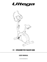
Training area in mm
(for home trainer and user)
Free area in mm
(Training area and security area
(rotating 60cm))
Cleaning, Checks and Storage of the Ergometer
bike:
1. Cleaning
Use only a less wet cloth for cleaning. Caution: Never use benzene,
thinner or other aggressive cleaning agents for surface cleaning as
this damage caused.
The device is only for private home use and for use suitable indoors.
Keep the unit clean and moisture from the device.
2. Storage
Plug out the power supply unit while intending the unit for more than
4 weeks not to use. Push the saddle slide toward the handlebar
and the seat support tube as deeply as possible into the frame.
Choose a dry storage in-house and put some spray oil to the pedal
bearings left and right and on the thread of the quick release for
saddle support.
Cover the bike to protect it from being discolor by any sunlight and
dirty through dust.
3. Checks
We recommend every 50 hours to review the screw connections for
tightness, which were prepared in the assembly. Every 100 operating
hours, you should put some spray oil at the pedal bearings left and
right to the thread of quick release for saddle support.
Troubleshooting
If you cannot solve the problem with the following information,
please contact the authorized service center.
Problem Possible Cause Solution
Computer has
no value at Dis-
play if you press
any key.
No power
adapter is well
plugged or wall
power is without
power.
Check that the power adapter
is properly plugged in, possibly
with another electric device
check if the wall power is fine.
Computer is
not counting
data and do not
switch on after
start cycling.
Sensor impulse
missing base on
not well plugged
connection
Check the plug connections at
computer and inside of handle-
bar support.
Computer is
not counting
data and do not
switch on after
start cycling.
Sensor impulse
missing base on
not correct posi-
tion of sensor.
Take off the cover and check
the distance between magnet
and Sensor. The magnet at
turning belt wheel should have
only less than < 5mm distance
against the sensor position.
No pulse value Pulse cable is
not plugged in.
Check the separately pulse
cable is well connected with
computer.
No pulse value Pulse sensors
not well connec-
ted
Screw out the screw for pulse
measurement and check if
plugs are well connected and no
damage at pulse cable.

28
Training instructions
You must consider the following factors in determining the amount of training
effort required in order to attain tangible physical and health benefits:
1. Intensity:
The level of physical exertion in training must exceed the level of normal
exertion without reaching the point of breathlessness and / or exhaustion.
A suitable guideline for effective training can be taken from the pulse rate.
During training this should rise to the region of between 70% to 85% of
the maximum pulse rate (see the table and formular for determination and
calculation of this).
During the first weeks, the pulse rate should remain at the lower end of this
region, at around 70% of the maximum pulse rate. In the course of the follo-
wing weeks and months, the pulse rate should be slowly raised to the upper
limit of 85% of the maximum pulse rate. The better the physical condition
of the person doing the exercise, the more the level of training should be
encreased to remain in the region of between 70% to 85% of the maximum
pulse rate. This should be done by lengthening the time for the training and
/ or encreasing the level of difficulty.
If the pulse rate is not shown on the computer display or if for safety reasons
you wish to check your pulse rate, which could have been displayed wrongly
due to error in use, etc., you can do the following:
a. Pulse rate measurement in the conventional way (feeling the pulse at the
wrist, for example, and counting the number of beats in one minute).
b. Pulse rate measurement with a suitable specialised device (available from
dealers specialising in health-related equipment).
2.Frequency
Most experts recommend a combination of health-conscious nutrition, which
must be determined on the basis of your training goal, and physical training
three times a week. A normal adult must train twice a week to maintain his
current level of condition. At least three training sessions a week are required
to improve one’s condition and reduce one’s weight. Of course the ideal
frequency of training is five sessions a week.
3. Planning the training
Each training session should consist of three phases: the warm-up phase,
the training phase, and the cool-down phase. The body temperature and
oxygen intake should be raised slowly in the warm-up phase. This can be
done with gymnastic exercises lasting five to ten minutes.
Then the actual training (training phase) should begin. The training exertion
should be relatively low for the first few minutes and then raised over a period
of 15 to 30 minutes such that the pulse rate reaches the region of between
70% to 85% of the maximum pulse rate.
In order to support the circulation after the training phase and to prevent
aching or strained muscles later, it is necessary to follow the training phase
with a cool-down phase. This should be consist of stretching exercises and
/ or light gymnastic exercises for a period of five to ten minutes.
Calculation formula: Maximum pulse rate = 220 - age
(220 minus your age)
90% of the maximum pulse rate = (220 - age) x 0.9
85% of the maximum pulse rate = (220 - age) x 0.85
70% of the maximum pulse rate = (220 - age) x 0.7
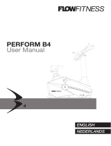
Warm up exercises (Warm Up)
Start your warm up by walking on the spot for at least 3 minutes and then perform the following gymnastic exercises to the body for the training phase to
prepare accordingly. The exercises do not overdo it and only as far run until a slight drag felt. This position will hold a while.
Reach with your left hand
behind your head to the right
shoulder and pull with the
right hand slightly to the left
elbow. After 20sec. switch
arm.
Bend forward as far forward
as possible and let your
legs almost stretched. Show
it with your fingers in the
direction of toe. 2 x 20sec.
Sit down with one leg
stretched out on the floor
and bend forward and try
to reach the foot with your
hands. 2 x 20sec.
Kneel in a wide lunge for-
ward and support yourself
with your hands on the
floor. Press the pelvis down.
Change after 20 sec leg.
After the warm-up exercises by some arms and legs shake loose.
Don’t finish the exercise phase abruptly, but will cycle leisurely something without resistance from to return to the normal pulse-zone. (Cool down) We re-
commend the warm-up exercises at the end of the training be conducted and to end your workout with shaking of the extremities.
You find further information on the subject warm-up exercises, stretch exer-
cises or general gymnastics exercises in our download area under www.
christopeit-sport.com
4. Motivation
The key to a successful program is regular training. You should set a fixed
time and place for each day of training and prepare yourself mentally for the
training. Only train when you are in the mood for it and always have your goal
in view. With continuous training you will be able to see how you are progres-
sing day by day and are approaching your personal training goal bit by bit.
/