Page is loading ...

1
Heimsport-Trainingsgerät
ET 6 VR
Montage- und Bedienungsanleitung für Bestell-Nr.
Notice de montage et d’utilisation du
No. de commande
Assembly and exercise instructions for Order No.
Montage- en bedieningshandleiding voor
Bestellnummer
GB
D
F
NL
91071(A)
RU
Инструкция по монтажу и эксплуатации
№ заказа

5
Nach Öffnen der Verpackung bitte kontrollieren, ob alle Teile ent-
sprechend der nachfolgenden Montageanleitung vorhanden sind.
Ist dies der Fall, können Sie mit dem Zusammenbau beginnen.
Wenn ein Bauteil nicht in Ordnung ist oder fehlt, oder wenn Sie in
Zukunft ein Ersatzteil benötigen, wenden Sie sich bitte an:
Adresse: Top-Sports Gilles GmbH
Friedrichstr. 55
42551 Velbert
Telefon: +49 (0) 20 51 - 6 06 70
Telefax: +49 (0) 20 51 - 6 06 74 4
e-mail: info@christopeit-sport.com
www.christopeit-sport.com
Stückliste - Ersatzteilliste
ET 6 VR Best.-Nr. 91071(A)
Technische Daten: Stand: 01. 09. 2009
l Magnet-Brems-System mit ca. 9Kg Schwungmasse
l Computergesteuerte 24 stufige Widerstandseinstellung
l 12 Trainingsprogramme
l 4 Herzfrequenzprogramme mit Zielpulsprogramm
l 5 individuelle Programme
l 1 manuelles Programm und 1 Zufallsprogramm
l 1Watt-Programm (drehzahlunabhängig)
Vorgabe der Wattleistung von 30-350Watt in 5 Watt Schritten
l CD mit NetAthlon Sofware für virtuelles Simultraining (10 Tage Vollversion)
(Nach 10Tagen bleibt 1 Rennstrecke, weitere Rennstrecken optional
erwerbbar bei www.simultrainer.com )
l Netzteil
l Handpulsmesssung/Empfänger für Pulsgurt im Computer
l Lenker und Sattel neigungsverstellbar
l Sattel vertikal und horizontal verstellbar
l USB Verbindungskabel for Interaktives Training mit NetAthlon
l Computer mit hinterleuchtetem LCD Display und gleichzeitiger Anzeige
von Zeit, Entfernung, Geschwindigkeit, RPM, Kalorien, Watt und Pulsfrequenz
l Geeignet bis zu einem Körpergewicht von max. 150Kg
l Stellmaße L96xB52xH140cm
Abbildungs- Bezeichnung Abmessung Menge Montiert an ET-Nummer
Nr. mm Stück
1 Grundrahmen 1 33-9107101-SI
2 Vorderer Fuß 1 1 33-9805-02-SI
3L Fußkappe mit Transportrollen Links 1 2 36-9107-29-BT
3R Fußkappe mit Transportrollen Rechts 1 2 36-9107-30-BT
4 Schlosschraube M8 x 52 2 1,2 39-10448-CR
5 Unterlegscheibe 8//16 12 4,10 39-10018-CR
6 Federring für M8 14 4,10,68 39-9864-CR
7 Hutmutter M8 2 4 39-9900-CR
8 Hinterer Fuß 1 1 33-9805-03-SI
9 Fußkappen 2 8 36-9107-33-BT
10 Innensechskantschraube M 8 x 15 10 1 39-9888-CR
11 Verkleidung Links 1 1+12 36-9107121-BT
12 Verkleidung Rechts 1 1+11 36-9107122-BT
13 Lenkerstützrohr 1 1 33-9107102-SI
14 Verbindungskabel 1 15,22 36-9107104-BT
15 Stellmotorkabel 1 14,48 36-9107106-BT
16 Sattelstützrohr 1 1,18 33-9805-05-SI
17 Stützrohrüberzug 1 16 36-9805-11-BT
18 Sattelschlitten 1 16 33-9814-05-SI
19 Sattel 1 19a 36-9107-06-BT
19a Sattelhalterung 1 18 36-9814-12-BT
20 Sterngriffmutter 1 44 36-9814-14-BT
21 Schnellverschluß 1 1 36-9805-13-BT
22 Computer 1 13 36-9107103-BT
23 Schraube M 5 x 12 2 22 39-9988
24 Handpulskabel 1 22 36-9107-07-BT
25 Lenkerüberzug 2 27 36-9805-15-BT
26 Pulsgriffeinheit 2 27 36-9107-08-BT
27 Lenker 1 13 33-9805-06-SI
28 Vordere Lenkerverkleidung 1 13,29 36-9107-34-BT
29 Hintere Lenkerverkleidung 1 13,28 36-9107-35-BT
30 Schraube M 5 x 20 2 13,28,29 39-10165
31 Schraube M 4 x 15 2 28,29 36-9805-41-BT
32 Sterngriffschraube 1 13 36-9805-19-BT
33 L Pedale Links 1 88 36-9805-20-BT
33 R Pedale Rechts 1 34 36-9805-21-BT
34 Pedalaufnahme Rechts 1 65 33-9805-07-SI
35 Netzgerät 6VoltDC/1000mA 1 50 36-9107105-BT
36 Schraube M 4 x 25 5 1,11,12 36-9805-42-BT
37 Schraube M 4 x 30 1 11,12 36-9805-43-BT
38 Rundverkleidung 2 89,90 36-9107-11-BT
39 Gleiter 1 1 36-9805-23-BT
Deutsch

6
Abbildungs- Bezeichnung Abmessung Menge Montiert an ET-Nummer
Nr. mm Stück
40 Schraube ¾“ x 10-32 4 65 36-9805-24-BT
41 Schraube für Höhenausgleich 2 8 36-9805-25-BT
42 Unterlegscheibe 10//20 3 18,78 36-9718-40-BT
43 Kugellager 6000ZZ 1 78 39-9998
44 Befestigungsteil 1 16,18 33-9814-09-SI
45 Vierkantstopfen 2 18 39-9881
46 Rundstopfen 2 27 36-9718-12-BT
47 Achsmutter 3/8x26 2 65 36-9107-12-BT
48 Stellmotor 1 1,55 36-9107107-BT
49 Anschlußbuchsenaufnahme 1 50 36-9107108-BT
50 Anschlußkabel mit Buchse 1 35+48 36-9107109-BT
51 Schraube M5 x 18 4 1,48 39-10190
52 Sensorhalter 2 53,98 36-9814-21-BT
53 Sensor 1 1 52 36-9107110-BT
54 Schraube M6 x 12 2 52 39-10078-SW
55 Seilzug 1 48,59 36-9107-17-BT
56 Feder 1 1,59 36-9107-18-BT
57 Selbstsichernde Mutter M 8 1 58 39-9818
58 Sechskantschraube M 8 x 52 1 1,59 36-9718-43-BT
59 Magnetbügel 1 1 33-9107-03-SI
60 Kugellager 6203ZZ 4 1,70 36-9805-31-BT
61 Sicherungsclip C17 3 65 36-9805-32-BT
62 Magnet 1 63 36-9107-19-BT
63 Riemenrad 1 65 33-9805-10-SI
64 Unterlegscheibe 17//22 1 63,65 36-9805-34-BT
65 Tretkurbelachse 1 60 33-9107-04-SI
66 Schraube M6 x 15 4 63,65,75 39-9911
67 Flachriemen 1 63,83 36-9805-35-BT
68 Sechskantschraube M8 x 15 2 1,69 39-9821
69 Halterung für Magnetbügel 1 1,59 33-9107-05-SI
70 Spannbügel 1 1 36-9107-20-BT
71 Spannfeder 1 70 36-9805-42-BT
72 Distanzstück 3 70 36-9805-43-BT
73 Unterlegscheibe 6//12 3 74 39-10013-VC
74 Schraube M 6 x 15 3 70 36-9805-44-BT
75 Selbstsichernde Mutter M6 5 74+95 39-9816-VC
76 Federring für M6 4 74 39-9865-SW
77 Schwungrad 1 78,79 33-9505-15-SI
78 Schwungradachse 1 79 33-9805-16-SI
79 Kugellager 6003ZZ 2 78,77 36-9107-21-BT
80 Gleitlager 1 78 36-9814-25-BT
81 Achsmutter 3/8“x9 1 78 39-9820-SW
82 Kugellager 6300ZZ 1 78 39-9946
83 Riemenrad 1 81,82 36-9814-28-BT
84 Unterlegscheibe 8//18 2 68 39-9966
85 Sicherungsclip C10 2 78 36-9805-36-BT
86 Mutter 3/8“ 2 78 39-9820
87 Schraube M 5 x 12 14 34,88 39-9988
88 Pedalaufnahme Links 1 65 33-9805-08-SI
89 Rundverkleidung 2 34+88 36-9107120-BT
90 Achsmutter 3/8“x3 1 78 39-9820-CR
91 Mutter M6 1 95 39-9861-VZ
92 Kunststoffscheibe 6//22 1 95 36-9107-23-BT
93 Unterlegscheibe 6//12 1 95 39-9993
94 Unterlegscheibe M30 1 77 36-9107-24-BT
95 Sechskantschraube M6x65 1 59 39-10411-SW
96 Karton 1 36-9107-25-BT
97 Montage und Bedienungsanleitung 1 36-9107119-BT
98 Sensor 2 1 52 36-9107111-BT
99 USB Verbindungskabel 1 22 36-9107112-BT
100 Multi-Gabelschlüssel 10/13/14/15 1 36-9107-27-BT
101 Multi-Innensechskantschlüssel 6mm/Cross 1 36-9107-28-BT

13
Contents
1. Summary of Parts Page 3 - 4
2. Important Recommendations and Safety Information Page 13
3. Parts List (List of spare parts) Page 14 - 15
4. Assembly Instructions With Exploded Diagrams Page 16 - 17
5. Mount, Use & Dismount Page 18
6. Computer instructions Page 19 - 20
7. Training Instructions Page 20
Dear customer,
We congratulate you on your purchase of this home training sports unit and
hope that we will have a great deal of pleasure with it. Please take heed of
the enclosed notes and instructions and follow them closely concerning
assembly and use.
Please do not hesitate to contact us at any time if you should have any
questions.
Top-Sports Gilles GmbH
Friedrichstr. 55
42551 Velbert
GB
Important Recommendations and
Safety Instructions
Our products are all tested and therefore represent the highest current safety
standards. However, this fact does not make it unnecessary to observe the
following principles strictly.
1. Assembly the machine exactly as described in the installation instructions
and use only the enclosed, specific parts of the machine contained in the
parts list. Before assembling, verify the completeness of the delivery against
the delivery notice and the completeness of the carton against the parts list
in the installation and operating instructions.
2. Check the firm seating off all screws, nuts and other connections before
using the machine for the first time and at regular intervals to ensure that
the trainer is in a safe condition.
3. Set up the machine in a dry, level place and protect it from moisture and
water. Uneven parts of the floor must be compensated by suitable measures
and by the provided adjustable parts of the machine if such are installed.
Ensure that no contact occurs with moisture or water.
4. Place a suitable base (e.g. rubber mat, wooden board etc.) beneath the
machine if the area of the machine must be specially protected against
indentations, dirt etc.
5. Before beginning training, remove all objects within a radius of 2 metres
from the machine.
6. Do not use aggressive cleaning agents to clean the machine and employ
only the supplied tools or suitable tools of your own to assemble the machine
and for any necessary repairs. Remove drops of sweat from the machine
immediately after finishing training.
7. WARNING! Your health can be impaired by incorrect or excessive train-
ing. Consult a doctor before beginning a planned training programme. He
can define the maximum exertion (pulse, Watts, duration of training etc.) to
which you may expose yourself and can give you precise information on the
correct posture during training, the targets of your training and your diet.
Never train after eating large meals.
8. Only train on the machine when it is in correct working order. Use original
spare parts only for any necessary repairs. WARNING: Replace the worm
parts immediately and keep this equipment out of use until repaired.
9. When setting the adjustable parts, observe the correct position and the
marked, maximum setting positions and ensure that the newly adjusted
position is correctly secured.
10. Unless otherwise described in the instructions, the machine must only
be used for training by one person at a time.
11. Wear training clothes and shoes which are suitable for fitness training
with the machine. Your clothes must be such that they cannot catch dur-
ing training due to their shape (e.g. length). Your training shoes should be
appropriate for the trainer, must support your feet firmly and must have
non-slip soles.
12. WARNING! If you notice a feeling of dizziness, sickness, chest pain or
other abnormal symptoms, stop training and consult a doctor.
13. Never forget that sports machines are not toys. They must therefore
only be used according to their purpose and by suitably informed and
instructed persons.
14. People such as children, invalids and handicapped persons should
only use the machine in the presence of another person who can give aid
and advice. Take suitable measures to ensure that children never use the
machine without supervision.
15. Ensure that the person conducting training and other people never move
or hold any parts of their body into the vicinity of moving parts.
16. At the end of its life span this product is not allowed to dispose over
the normal household waste, but it must be given to an assembly point for
the recycling of electric and electronic components. You may find the symbol
on the product, on the instructions or on the packing.
The materials are reusable in accordance with their marking. With the re-use,
the material utilization or the protection of our environment. Please ask the
local administration for the responsible disposal place.
17. For speed dependent operation mode, the braking resistance level can
be adjustable manually and the variations of power will depend on the pe-
daling speed. For speed independent operation mode, the user can set the
wanted power consumption level in Watt, constant power level will be kept
by various braking resistance levels, that will be determined automatically
by system. That is independent on the pedaling speed.
18. The unit has a resistance device with 24 levels. This makes it possible
to increase or reduce the braking resistance and thus the amount of effort
required in the training. Turning the button into „-“ reduces the braking
resistance and thus the amount of effort required in the training. Turning
the button into „+“ increases the braking resistance and thus the amount
of effort required in the training.
19. The maximum permissible load (=body weight) is specified as 150 kg.
English

14
Please check after opening the packing that all the parts shown in
the following parts lists are there. Once you are sure that this is the
case, you can start assembly.
Please contact us if any components are defective or missing, or if
you need any spare parts or replacements in future:
Adresse: Top-Sports Gilles GmbH
Friedrichstr. 55
42551 Velbert
Telefon: +49 (0) 20 51 - 6 06 70
Telefax: +49 (0) 20 51 - 6 06 74 4
e-mail: info@christopeit-sport.com
www.christopeit-sport.com
Illustration Designation Dimensions Quantity Attached to ET number
No. mm illustration No.
1 Main frame 1 33-9107101-SI
2 Front foot 1 1 33-9805-02-SI
3L Front foot cover Left 1 2 36-9107-29-BT
3R Front foot cover Right 1 2 36-9107-30-BT
4 Carriage bolt M8 x 52 2 1,2 39-10448-CR
5 Washer 8//16 12 4,10 39-10018-CR
6 Spring washer for M8 14 4,10,68 39-9864-CR
7 Cap nut M8 2 4 39-9900-CR
8 Rear foot 1 1 33-9805-03-SI
9 Rear foot Cover 2 8 36-9107-33-BT
10 Allen head screw M 8 x 15 10 1 39-9888-CR
11 Left chain cover 1 1+12 36-9107121-BT
12 Right chain cover 1 1+11 36-9107122-BT
13 Handlebar post 1 1 33-9107102-SI
14 Computer upper cable 1 15,22 36-9107104-BT
15 Computer lower cable 1 14,48 36-9107106-BT
16 Saddle post 1 1,18 33-9805-05-SI
17 Plastic collar 1 16 36-9805-11-BT
18 Movable seat post 1 16 33-9814-05-SI
19 Saddle 1 19a 36-9107-06-BT
19a Saddle holder 1 18 36-9814-12-BT
20 Star grip nut 1 44 36-9814-14-BT
21 Seat knob 1 1 36-9805-13-BT
22 Computer 1 13 36-9107103-BT
23 Screw M 5 x 12 2 22 39-9988
24 Hand pulse wire 1 22 36-9107-07-BT
25 Foam Grip 2 27 36-9805-15-BT
26 Pulse grip unit 2 27 36-9107-08-BT
27 Handlebar 1 13 33-9805-06-SI
28 Back handlebar cover 1 13,29 36-9107-34-BT
29 Front handlebar cover 1 13,28 36-9107-35-BT
30 Screw M 5 x 20 2 13,28,29 39-10165
31 Screw M 4 x 15 2 28,29 36-9805-41-BT
32 Handlebar screw 1 13 36-9805-19-BT
33 L Pedal left 1 88 36-9805-20-BT
33 R Pedal right 1 34 36-9805-21-BT
34 Cross frame right 1 65 33-9805-07-SI
35 Adaptor 6VoltDC/1000mA 1 50 36-9107105-BT
36 Screw M 4 x 25 5 1,11,12 36-9805-42-BT
37 Screw M 4 x 30 1 11,12 36-9805-43-BT
38 Turning plate cover 2 89,90 36-9107-11-BT
39 Saddle support tube insert 1 1 36-9805-23-BT
40 Screw ¾“ x 10-32 4 65 36-9805-24-BT
Parts list – List of spare parts
ET 6 VR order No. 91071(A)
Technical data: Issue: 01. 09. 2009
l Magnetic-Brake-System with approx. 9Kg flywheel mass
l Computer controlled resistance with 24 level adjustment
l 12 stored xercise programs
l 4 H.R.C. programs with target H.R.C. program
l 5 User programs
l 1 manually program and 1 random program
l 1 watt program (RPM independent)
Enter of Watt from 30-350 with 5Watt steps)
l CD with NetAthlon Software for virtual simultraining (10 days full version)
After 10 days you keep 1 race, more races are available to buy from
www.simultrainer.com )
l AC adapter
l Handpulse measurement/Pulse belt receiver included
l Handlebar and Sattel incline adjustable
l Saddle vertical and horizontally adjustable
l USB connection cable for web racing with NetAthlon
l Computer with easy to view Back/Light LCD Display and 7 windows
simultaneously show time, distance, speed, Watt, calories, RPM and Pulse.
l Load max. 150Kg body weight
l Space requirement approx. L96xB52xH140cm

15
English
Illustration Designation Dimensions Quantity Attached to ET number
No. mm illustration No.
41 Round screw for adjustable height 2 8 36-9805-25-BT
42 Washer 10//20 3 18,78 36-9718-40-BT
43 Bearing 6000ZZ 1 78 39-9998
44 Fix plate 1 16,18 33-9814-09-SI
45 Plastic bush 2 18 39-9881
46 Handlebar cap 2 27 36-9718-12-BT
47 Axle nut 3/8x26 2 65 36-9107-12-BT
48 Servo motor 1 1,55 36-9107107-BT
49 DC cable support 1 50 36-9107108-BT
50 DC cable 1 35+48 36-9107109-BT
51 Screw M5 x 18 4 1,48 39-10190
52 Sensor bracket 2 53,98 36-9814-21-BT
53 Sensor 1 1 52 36-9107110-BT
54 Screw M6 x 12 2 52 39-10078-SW
55 Wire rod 1 48,59 36-9107-17-BT
56 Small spring 1 1,59 36-9107-18-BT
57 Nylon nut M 8 1 58 39-9818
58 Hex head bolt M 8 x 52 1 1,59 36-9718-43-BT
59 Magnetic holder 1 1 33-9107-03-SI
60 Bearing 6203ZZ 4 1,70 36-9805-31-BT
61 Clip C C17 3 65 36-9805-32-BT
62 Magnet 1 63 36-9107-19-BT
63 Rear pulley 1 65 33-9805-10-SI
64 Washer 17//22 1 63,65 36-9805-34-BT
65 Axle for pulley 1 60 33-9107-04-SI
66 Screw M6 x 15 4 63,65,75 39-9911
67 Belt 1 63,83 36-9805-35-BT
68 Hex head screw M8 x 15 2 1,69 39-9821
69 Magnetic holder bracket 1 1,59 33-9107-05-SI
70 Bracket 1 1 36-9107-20-BT
71 Carge spring 1 70 36-9805-42-BT
72 Spacer sleeve 3 70 36-9805-43-BT
73 Washer 6//12 3 74 39-10013-VC
74 Screw M 6 x 15 3 70 36-9805-44-BT
75 Nylon nut M6 5 74+95 39-9816-VC
76 Spring washer For M6 4 74 39-9865-SW
77 Flywheel 1 78,79 33-9505-15-SI
78 Flywheel axle 1 79 33-9805-16-SI
79 Bearing 6003ZZ 2 78,77 36-9107-21-BT
80 Metal bushing 1 78 36-9814-25-BT
81 Axle nut 3/8“x9 1 78 39-9820-SW
82 Bearing 6300ZZ 1 78 39-9946
83 Front pulley 1 81,82 36-9814-28-BT
84 Washer 8//18 2 68 39-9966
85 Clip C10 2 78 36-9805-36-BT
86 Nut 3/8“ 2 78 39-9820
87 Screw M 5 x 12 14 34,88 39-9988
88 Cross frame left 1 65 33-9805-08-SI
89 Turning plate 2 34,88 36-9107120-BT
90 Axle nut 3/8“x3 1 78 39-9820-CR
91 Nut M6 1 95 39-9861-VZ
92 Plastic washer 6//22 1 95 36-9107-23-BT
93 Washer 6//12 1 95 39-9993
94 Washer M30 1 77 36-9107-24-BT
95 Hex head screw M6x65 1 59 39-10411-SW
96 Carton 1 36-9107-25-BT
97 Installation and operating instructions 1 36-9107119-BT
98 Sensor 2 1 52 36-9107111-BT
99 Computer upper cable USB 1 22 36-9107112-BT
100 Hex wrench 10/13/14/15 1 36-9107-27-BT
101 Allen wrench 6mm/Cross 1 36-9107-28-BT

16
Assembly Instructions
Before beginning assembly, be sure to observe our recommendat-ions
and safety instruction. Remove all the part of your cycle from the carton
and place them on the floor carefully.
Some parts are pre-assembled.
Step 1:
Attach the stabilizer
1. Attach the rear stabilizer (8) assembled with 2 rear cross bar caps (9)
and 2 adjustable knob (41) to main frame (1), using 2 allen head bolts
(10), 2 washers (5) and 2 spring washers(6).
You can use adjustable knob (41) to level the bike.
2. Attach the front stabilizer (2) assembled with 2 front cross bar caps (3)
to main frame (1), using 2 carriages bolts (4), 2 washers (5), 2 spring
washers (6) and two cap nuts (7).
Step 2:
Attach the seat and seat post
1. Slide the plastic collar (17) to cover the seat post (16).
2. Insert the seat post (16) to seat post mounting tube of main frame
(1) and secure in position with the seat post quick release (21).
3. Put the clamp of seat (19) to the seat slide post (18A) and tighten
the seat firmly into your desired position.
4. After assembling the seat slide post (18) at the seat post with washer
(42) star grip nut (20), you can move the hole of seat slide post to adjust
your desired position.
Step 3:
Attach the front post
1. Remove the pre-assembled 4 allen head bolt (10), 4 washers (5) and
4 spring washers (6) from main frame(1).
2. Attach the front post (13) to the front post mounting tube of main
frame (1) and connect the plug of middle section motor cable (14) to
the socket of the motor cable (15).
3. Insert the front post (13) to main frame (1) and secure, using 4 allen
head bolts (10), 4 spring washers (6) and 4 washers (5).

17
English
Step 5:
Attach the pedal
1. Attach the pedal straps to the pedals (33R/33L).
NOTE: The end with four adjustable holes must be set outwards.
2. The pedals (33R/33L) are marked with „R“ & „L“
NOTE: Right and Left are specified as viewed seated on the machine
during training.
Connect each pedal (33R/33L) to the matching crank arm (34+88)
(NOTE: The right pedal „R“ should be threaded on clockwise. The
left pedal „L“ should be threaded on counter-clockwise.)
Step 6:
Attach the power
1. Please insert the plug of adaptor (35) to the jack (50) of chain guard.
2. Please insert the adaptor (35) to the jack of wall power (230 V/50Hz)
Step 7:
Checks
1. Check the correct installation and function of all screwed and plug
connections.
Installation is thereby complete.
2. When everything is in order, familiarize yourself with the machine at a
low resistance
Setting and make your individual adjustments.
Note:
Please keep the tool set and the instructions in a safe place as these
may be required for repairs or spare parts orders becoming necessary
later.
Step 4:
Attach the handlebar and computer
1. Put the plug of middle section motor cable (14) into the socket from
monitor (22) backside.
2. Attach the monitor (22) to top monitor bracket of front post (13) with
screws (23). (Attention: Ensure that the cable loom are not crunched
or pinched during installation.)
3. Attach the handlebar (27) with hand pulses (26) to welded clamp of front
post (13) and secure with clamp, clamp decoration cover (28) and star
grip screw (32) in your desired position. Fix the decoration cap (28) with
screw (30).
4. Insert the plug of hand pulse wire (24) to the jack of the monitor (22).
Attach the handlebar covers (28 + 29) with screws (30 + 31).

18
Mount, Use & Dismount
Transportation of Equipment:
There are two rollers equipped on the front foot. For moving, you can lift up the rear foot and drive it to where you would like
to locate or store it.
Adjustment – Seat Position
For an effective workout, the seat must be adjusted properly. While your are pedaling, your Knees should be slightly bent when
the pedals are in the farthest position. In order to adjust the seat, unscrew the knob few turns and draw it out slightly. Adjust the
seat to the right height, then release the knob and tighten it all the way.
Important:
Make sure to put the knob back into place in the seat post and tighten it completely. Never exceed the maximum height of the
seat. Always get off the bicycle before making any adjustment.
Mount, Use & Dismount
Mount:
a. After the seat is adjusted to properly position, insert your foot into retaining strap of pedal step on the pedal and hold
the handlebar tightly.
b. Try to put whole body weight on your foot and simultaneously cross over the trainer and land your another foot on the
other side.
c. Now you are in the position to start your training.
Use:
a. Keep you hands on the handlebar, and both feet are insert into retaining straps of both pedal properly.
b. Pedal your exercise bike by your both feet alternately.
c. Then you can increase the pedaling speed gradually and adjust braking resistance levels to increase the exercise intension.
Dismount:
a. Slow down the pedaling speed until it comes to rest.
b. Keep the left hand grabbing the left handlebar tightly, put your feet cross over the equipment and land on the floor, then
land the other one.
This training equipment is a stationary exercise machine used to simulate without causing excessive pressure to the joints,
hence decreasing the risk of impact injuries.
Exercise bike offer a non-impact cardiovascular workout that can vary from light to high intensity based on the resistance prefe-
rence set by the user. It will strengthen your muscles of legs and increase cardio capacity and maintain fitness of your body also.

19
English
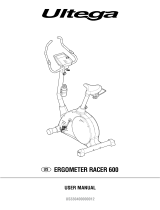
Computer instructions for ET 6 VR
FUNCTIONS
SCAN : Alternates between WATTS/CALORIES
and RPM/SPEED
6seconds per display
RPM : 0~15~999
SPEED : 0.0~99.9 km/h
TIME : 00:00~99:59.
DISTANCE : 0.00~99.99 km
CALORIES : 0~999 kcal
WATTS : 0~999 watts
WATTS :10~350
HEART-SYMBOL : flashes (only by using pulse measurement)
PULSE : P~30~240 max. value is available.
MANUAL : 1~24 level
PROGRAM : P1~P12 (exercise profiles)
PERSONAL : U1~U4
H.R.C : 55%, 75%, 90%, IND (Target H.R.C.)
RANDOM : U1~U4
USER DATA : U0 ~U4 (U1 ~ U4 memorized user data)
KEYS
1. Enter -key : Press key to select function and confirm setting value.
If press key for 2 seconds get back start modus to select User Input of User
Data (Sex/Age/Height Weight)
2. +/- -Turn-key : Increase or decrease the pre setting values.
3. START/STOP -key: Starts or Stops the programs.
4. RECOVERY -key : Fitness-Test with automatically evaluate your fitness
level (F1-F6)
5. QUICK START -key : Starts manually program directly
6. RESET –key: Press this key to get back to start modus to select program
If press key for 2 seconds get back start modus to select User
Input of User Data (Sex/Age/Height Weight)
DISPLAYS
1. Time: Displays minutes and seconds. The computer count up if no
time was pre-entered. If pre-entered time with +/- turn-key, the value counts
down. After reach value 0:00 a signal sounds for end of exercising.
2. Distance: Displays kilo meters. The computer count up if no
distance was pre-entered. If pre-entered distance with +/- turn-key, the value
counts down. After reach value 0:00 a signal sounds for end of exercising.
3. RPM: Displays the current pedal turns per minute.
4. WATT: Displays the current power in watts during exercising.(Level & RPM)
5. SPEED: Displays the speed with kilo meters per hour.
6. CALORIES: Displays the kilocalories of exercising.
7. PULSE: Displays heart beat per minute (H.R.C.) during the exercising by
using Hand pulse measurement or pulse belt.
START
Put the AC adapter into wall power and connect the AC adapter plug with
item.
The Computer starts with a mall sound and displays start menu.
HANDLING
1) At start menu you can select user and put in user data (Sex/Age/Height
Weight) by using turn-key and confirm data by press Enter key.
2) Select program of Manual- ; Program- ( P1-P12 Pre-set Profiles); Watt-;
Personal-; HRC- and Random-program) with +/- turn-key and confirm with
Enter-key.
3) If the program is entered you can select at Program one exercise program
from P1-P12, and at H.R.C. one H.R.C. program of 55%; 75%; 90% or target
by using +/-turn-key and confirm with Enter-key.
After that you can pre-set data like of TIME / DISTANCE / CALORIES /
PULSE / WATTS depend of selected program. Use +/- turn-key to adjust
the value and confirm with Enter-key.
4) START/STOP-key press to start with exercising.
PROGRAMS
1) MANUAL -program
Einstellung des Widerstandes während des Trainings möglich. Wider-
standsstufe
anhand der Balkenanzeige auf dem Display ablesbar,(1-24)
Einstellung der Trainingsparameter ZEIT / ENTFERNUNG / KALORIEN /
PULS möglich.
Mit der Taste START/STOP beginnen und stoppen Sie das manuelle Pro-
gramm.
2) PROGRAM (P1-P12)
12 automatically Exercise programs with different Profiles (P1~P12).
During the exercising you can adjust the resistance into higher or lower level
Pres-settings of Time / Distance / Calories and Pulse is possible.
3) WATT (independent Watt-program)
Pre-setting of Watt value with +/- turn -key. Display starts at „100“.
Possibility to adjust Watt in 5Watt load steps from 10-350Watt. Have you
pre-set a Watt value the resistance will adjust automatically in regard to
the RPM. (If you exercise slowly the resistance will become harder, if you
exercise with higher speed the resistance will adjust lower according to the
Watt you pre-set.)
4) PERSONAL (U0-U4)
Create your own exercise profile. At User programs you can adjust the
level of every individual segment by yourself. Use +/- turn-key to adjust the
resistance level and confirm with Enter -key. The Programs U1-U4 will keep
the data saved for future.
U 0 can be set same as U1-U4 but cannot be saved.
5) H.R.C (heart rate control programs)
Programs to control you heart frequency. Select you own target heart rate
and choose one of pre-set programs of 55%, 75%, 90% or target heart rate.
With help of the pre-entered User data of AGE you ensure that your target
heart rate is set correctly. The PULS display will flash when you reached the
target heart rate according to the program you have selected.
1) 55% -- DIÄT-PROGRAM
2) 75% -- HEALTH-PROGRAM
3) 90% -- SPORTS-PROGRAM
4) TARGET—user set target heart rate
During the exercising you cannot adjust the resistance into higher or lower
level.

20
6) RANDOM
This exercise computer creates amazing exercising program chart by auto-
random producing.
Sometimes user is tired of user pre-setting program charts, he/she can
choose RANDOM to let computer auto-producing it’s program chart. There
are over hundred programs can be offered playing.
RECOVERY:
After you finish your workout with pulse, press this key and put both hands
on the pulse measurement.
Time will count down from 1 Minute and then your fitness level from F1-F6
will be displayed.
NOTE: During RECOVERY, no other display will operate.
PULSE RATE:
The whole set of heart rate detector include 2 sensors each side. Each
sensor has 2 pieces of metal parts. The correct way to get detected is
to gently hold both metal parts each hand. With the good signals picked
up by the computer, the heart mark in the HEART Display shall flash.
(You can also use a pulse belt which is not codified and has got a
frequency of 5.0 – 5,5 KHz)
NOTICE
1. Option: Plug in AC adapter (6 VOLT=DC/ 1000 mA).
2. Option: USB cable for connection of Exercise-Computer personal home
computer.
for inter activity „Simultraining“ with NetAthlon Software
3. Keep moisture away from computer.
WEB-RACING
The key function of Web racing with NetAthlon Software as follows:
+/- turn-key increase or decrease the value. Enter-key starts the Web racing
games Start/Stop-key stops the web racing game
All information for Installation of Software and Using the programs you find on
the NetAthlon Software CD. The hotline for help and Service you find on :
www.simultrainer.com
Training instructions
You must consider the following factors in determining the amount of training
effort required in order to attain tangible physical and health benefits:
1. Intensity:
The level of physical exertion in training must exceed the level of normal
exertion without reaching the point of breathlessness and / or exhaustion.
A suitable guideline for effective training can be taken from the pulse rate.
During training this should rise to the region of between 70% to 85% of
the maximum pulse rate (see the table and formular for determination and
calculation of this).
During the first weeks, the pulse rate should remain at the lower end of
this region, at around 70% of the maximum pulse rate. In the course of
the following weeks and months, the pulse rate should be slowly raised to
the upper limit of 85% of the maximum pulse rate. The better the physical
condition of the person doing the exercise, the more the level of training
should be encreased to remain in the region of between 70% to 85% of the
maximum pulse rate. This should be done by lengthening the time for the
training and / or encreasing the level of difficulty.
If the pulse rate is not shown on the computer display or if for safety reasons
you wish to check your pulse rate, which could have been displayed wrongly
due to error in use, etc., you can do the following:
a. Pulse rate measurement in the conventional way (feeling the pulse at the
wrist, for example, and counting the number of beats in one minute).
b. Pulse rate measurement with a suitable specialised device (available from
dealers specialising in health-related equipment).
2.Frequency
Most experts recommend a combination of health-conscious nutrition, which
must be determined on the basis of your training goal, and physical training
three times a week. A normal adult must train twice a week to maintain his
current level of condition. At least three training sessions a week are required
to improve one’s condition and reduce one’s weight. Of course the ideal
frequency of training is five sessions a week.
3. Planning the training
Each training session should consist of three phases: the warm-up phase,
the training phase, and the cool-down phase. The body temperature and
oxygen intake should be raised slowly in the warm-up phase. This can be
done with gymnastic exercises lasting five to ten minutes.
Then the actual training (training phase) should begin. The training exertion
should be relatively low for the first few minutes and then raised over a
period of 15 to 30 minutes such that the pulse rate reaches the region of
between 70% to 85% of the maximum pulse rate.
In order to support the circulation after the training phase and to prevent
aching or strained muscles later, it is necessary to follow the training phase
with a cool-down phase. This should be consist of stretching exercises and
/ or light gymnastic exercises for a period of five to ten minutes.
Calculation formula: Maximum pulse rate = 220 - age
(220 minus your age)
90% of the maximum pulse rate = (220 - age) x 0.9
85% of the maximum pulse rate = (220 - age) x 0.85
70% of the maximum pulse rate = (220 - age) x 0.7
4. Motivation
The key to a successful program is regular training. You should set a fixed
time and place for each day of training and prepare yourself mentally for
the training. Only train when you are in the mood for it and always have
your goal in view. With continuous training you will be able to see how you
are progressing day by day and are approaching your personal training
goal bit by bit.

22
Après avoir ouvert l’emballage, veuillez contrôler s’il y a toutes les
pièces conformément à la liste suivante. Si c’est le cas, vous pouvez
commencer l’assemblage.
Si une pièce n’est pas correcte, s’il manque une pièce ou si vous
avez besoin d’une pièce de rechange à l’avenir, veuillez vous
adresser à :
Adresse: Top-Sports Gilles GmbH
Friedrichstr. 55
42551 Velbert
Telefon: +49 (0) 20 51 - 6 06 70
Telefax: +49 (0) 20 51 - 6 06 74 4
e-mail: info@christopeit-sport.com
www.christopeit-sport.com
Schéma Désignation Dimensions Quantité Monté sur Numéro ET
n° en mm Unités schéma n°
1 Châssis 1 33-9107101-SI
2 Tube de piet avant 1 1 33-9805-02-SI
3L Coiffe avec unite des roulettes de transport gauche 1 2 36-9107-29-BT
3R Coiffe avec unite des roulettes de transport droite 1 2 36-9107-30-BT
4 Vis à tête bombèe et collet carrè M8 x 52 2 1,2 39-10448-CR
5 Rondelle intercalaire 8//16 12 4,10 39-10018-CR
6 Bague ressort for M8 14 4,10,68 39-9864-CR
7 Ecrou à chapeau M8 2 4 39-9900-CR
8 Tube de pied arrière 1 1 33-9805-03-SI
9 Coiffe pour N° 8 2 8 36-9107-33-BT
10 Vis à tête ronde et 6 pans creux M 8 x 15 10 1 39-9888-CR
11 Capotage gauche 1 1+12 36-9107121-BT
12 Capotage droit 1 1+11 36-9107122-BT
13 Tube d`appui du guidon 1 1 33-9107102-SI
14 Faisceau de fils de l`oerinateur, sortant du guidon 1 15,22 36-9107104-BT
15 Câble de connexion du moteur 1 14,48 36-9107106-BT
16 Tube dàppui du guidon 1 1,18 33-9805-05-SI
17 Gaine du tube d`appui de la selle 1 16 36-9805-11-BT
18 Pièce coulissante de selle 1 16 33-9814-05-SI
19 Selle 1 19a 36-9107-06-BT
19a Fixation de selle 1 18 36-9814-12-BT
20 Ecrou à poignée étoile 1 44 36-9814-14-BT
21 Fermeture à vis à clé 1 1 36-9805-13-BT
22 Ordinateur 1 13 36-9107103-BT
23 Vis M 5 x 12 2 22 39-9988
24 Faisceau de fils de mesure du pouls 1 22 36-9107-07-BT
25 Revêtement de guidon 2 27 36-9805-15-BT
26 Unité à poignée de mesure du pouls 2 27 36-9107-08-BT
27 Guidon 1 13 33-9805-06-SI
28 Revêtement avant pour de guidon 1 13,29 36-9107-34-BT
29 Revêtement arrière de guidon 1 13,28 36-9107-35-BT
30 Vis M 5 x 20 2 13,28,29 39-10165
31 Vis M 4 x 15 2 28,29 36-9805-41-BT
32 Vis à poignée étoile 1 13 36-9805-19-BT
33 L Pédale gauche 1 88 36-9805-20-BT
33 R Pédale droite 1 34 36-9805-21-BT
34 Pédalier droite 1 65 33-9805-07-SI
35 Appareil d’alimentation électrique 6VoltDC/1000mA 1 50 36-9107105-BT
36 Vis M 4 x 25 5 1,11,12 36-9805-42-BT
37 Vis M 4 x 30 1 11,12 36-9805-43-BT
38 Revêtement Rondelle 2 89,90 36-9107-11-BT
39 Insert en caoutchouc 1 1 36-9805-23-BT
40 Vis ¾“ x 10-32 4 65 36-9805-24-BT
41 Palier 2 8 36-9805-25-BT
Liste des pièces- Liste des pièces de rechange
ET 6 VR N° de commande 91071(A)
Caractéristiques techniques : Version du : 01/ 09/ 2009
• Masse tournante: environ 9 kg
• Réglage automatisé de 24 niveaux de résistance
• 12 programmes de résistance prévus
• 4 programmes de fréquence cardiaque (fonctionnant par impulsion)
• 5 programmes personnalisables
• 1 manuel programme et 1 programme de hazard
• 1 programme indépendant de la vitesse de rotation (par défaut, puissance en watt)
• CD avec NetAthlon Software pour virtuellment entraînement (Simultraining) (10 siège une pleine
version apres 10 siège 1 espace de course.optional différent espace de course acheter à
www.simultrainer.com )
• Appareil d’alimentation électrique
• Mesure des pulsations au guidon/ L’ordinateur est équipé d’un récepteur des
données en provenance de l’émetteur de fréquence cardiaque.
• Réglable inclinaison de la guidon et selle
• Réglable horizontal et vertical de la selle (verrouillage rapide)
• USB cable de connexion pour virtuellment entraînement avec NetAthlon
• L’écran de l’ordinateur dispose de l’afchage digital des sept types de données
suivantes: Durée, vitesse, distance qui correspond plus ou moins à la dépense
de calories, les pulsations, les watts et la récupération.
• Adapté pour des poids jusqu’environ 150 kg.
• Dimensions : L 96 x l 52 x H 140 cm.

23
Français
Schéma Désignation Dimensions Quantité Monté sur Numéro ET
n° en mm Unités schéma n°
42 Rondelle intercalaire 10//20 3 18,78 36-9718-40-BT
43 Roulement à billes 6000ZZ 1 78 39-9998
44 Fixation 1 16,18 33-9814-09-SI
45 Bouchon carré 2 18 39-9881
46 Bouchon rond 2 27 36-9718-12-BT
47 Ecrou de axe 3/8x26 2 65 36-9107-12-BT
48 Servomoteur 1 1,55 36-9107107-BT
49 Fixation de N°. 50 1 50 36-9107108-BT
50 Câble de d’alimentation électrique 1 35+48 36-9107109-BT
51 Vis M5 x 18 4 1,48 39-10190
52 Fixation de capteur 2 53,98 36-9814-21-BT
53 Capteur 1 1 52 36-9107110-BT
54 Vis M6 x 12 2 52 39-10078-SW
55 Câble gainé 1 48,59 36-9107-17-BT
56 Ressort 1 1,59 36-9107-18-BT
57 Ecrou autobloquant M 8 1 58 39-9818
58 Vis hexagonal M 8 x 52 1 1,59 36-9718-43-BT
59 Etrier magnétique 1 1 33-9107-03-SI
60 Roulement à billes 6203ZZ 4 1,70 36-9805-31-BT
61 Bague de sécurité C17 3 65 36-9805-32-BT
62 Aimant 1 63 36-9107-19-BT
63 Roue à courroie 1 65 33-9805-10-SI
64 Rondelle intercalaire 17//22 1 63,65 36-9805-34-BT
65 Axe de pédalier 1 60 33-9107-04-SI
66 Vis M6 x 15 4 63,65,75 39-9911
67 Courroie trapézoidale 1 63,83 36-9805-35-BT
68 Vis hexagonal M8 x 15 2 1,69 36-9821
69 Fixation pour Etrier magnétique 1 1,59 33-9107-05-SI
70 Étrier de serrage 1 1 36-9107-20-BT
71 Ressort d´ étrier de serrage 1 70 36-9805-42-BT
72 Pièce d`ecartement 3 70 36-9805-43-BT
73 Rondelle intercalaire 6//12 3 74 39-10013-VC
74 Vis M 6 x 15 3 70 36-9805-44-BT
75 Ecrou autobloquant M6 5 74+95 39-9816-VC
76 Rondelle elastique bombée For M6 4 74 39-9865-SW
77 Volant cinétique 1 78,79 33-9505-15-SI
78 Axe volant cinètique 1 79 33-9805-16-SI
79 Roulement à billes 6003ZZ 2 78,77 36-9107-21-BT
80 Roulement 1 78 36-9814-25-BT
81 Ecrou de axe 3/8“x9 1 78 39-9820-SW
82 Roulement à billes 6300ZZ 1 78 39-9946
83 Roue à courroie 1 81,82 36-9814-28-BT
84 Rondelle intercalaire 8//18 2 68 39-9966
85 Bague de sécurité C10 2 78 36-9805-36-BT
86 Ecrou 3/8“ 2 78 39-9820
87 Vis M 5 x 12 14 34,88 39-9988
88 Pédalier gauche 1 65 33-9805-08-SI
89 Revêtement rondelle 2 34+88 36-9107120-BT
90 Ecrou de axe 3/8“x3 1 78 39-9820-CR
91 Ecrou M6 1 95 39-9861-VZ
92 Rondelle de plastique 6//22 1 95 36-9107-23-BT
93 Rondelle 6//12 1 95 39-9993
94 Rondelle M30 1 77 36-9107-24-BT
95 Vis hexagonal M6x65 1 59 39-10411-SW
96 Carton 1 36-9107-25-BT
97 Notice de montage et dùtilisation 1 36-9107119-BT
98 Capteur 2 1 52 36-9107111-BT
99 Faisceau de fils de l`oerinateur, sortant du guidon USB 1 22 36-9107112-BT
100 Kit d`outillage 6 mm 1 36-9107-28-BT
101 Kit d`outillage 10/13/14/15 1 36-9107-27-BT

31
Nederlands
Afbeeldings- Beschrijving Afmetingen Aantal Gemonteerd aan ET-nummer
nr. mm stuks afbeeldingsnr.
1 Basisframe 1 33-9107101-SI
2 Voorste voetbuis 1 1 33-9805-02-SI
3L Voet kappen met transportrollen links 1 2 36-9107-29-BT
3R Voet kappen met transportrollen rechts 1 2 36-9107-30-BT
4 Slotschroef M8 x 52 2 1,2 39-10448-CR
5 Onderlegplatje 8//16 12 4,10 39-10018-CR
6 Veerring for M8 14 4,10,68 39-9864-CR
7 Hefmoer M8 2 4 39-9900-CR
8 Achterste voetbuis 1 1 33-9805-03-SI
9 Voet kappen 2 8 36-9107-33-BT
10 Rondkopschroef met binnenzeskant M 8 x 15 10 1 39-9888-CR
11 Linkse bekleding 1 1+12 36-9107121-BT
12 Rechtse bekleding 1 1+11 36-9107122-BT
13 Steunpijp 1 1 33-9107102-SI
14 Stelmotor verbindingskabel 1 15,22 36-9107104-BT
15 Stelmotor 1 14,48 36-9107106-BT
16 Steunbuis voor zadel 1 1,18 33-9805-05-SI
17 Afdekking zadel steunbuis 1 16 36-9805-11-BT
18 Zadelglijder 1 16 33-9814-05-SI
19 Zadel 1 19a 36-9107-06-BT
19a Zadelopname 1 18 36-9814-12-BT
20 Stergreepmoer 1 44 36-9814-14-BT
21 Snelslot 1 1 36-9805-13-BT
22 Computer 1 13 36-9107103-BT
23 Schroef M 5 x 12 2 22 39-9988
24 Pulskabel 1 22 36-9107-07-BT
25 Stuurovertrek 2 27 36-9805-15-BT
26 Handpulseenheid 2 27 36-9107-08-BT
27 Stuur 1 13 33-9805-06-SI
28 Voorste Stuurafdekkap 1 13,29 36-9107-34-BT
29 Achterste Stuurafdekkap 1 13,28 36-9107-35-BT
30 Schroef M 5 x 20 2 13,28,29 39-10165
31 Schroef M 4 x 15 2 28,29 36-9805-41-BT
32 Stergreepschroef 1 13 36-9805-19-BT
33 L Pedaal Links 1 88 36-9805-20-BT
33 R Pedaal Rechts 1 34 36-9805-21-BT
34 Pedaalopname rechts 1 65 33-9805-07-SI
35 Nettoestel 6VoltDC/1000mA 1 50 36-9107105-BT
36 Schroef M 4 x 25 5 1,11,12 36-9805-42-BT
37 Schroef M 4 x 30 1 11,12 36-9805-43-BT
38 Ronde afdekking 2 89,90 36-9107-11-BT
39 Glijder 1 1 36-9805-23-BT
40 Schroef 3/4“ x 10-32 4 65 36-9805-24-BT
41 Schroef voor hoogtecompensatie 2 8 36-9805-25-BT
Controleer na het openen van de verpakking a.u.b. aan de hand van
de onderstaande stuklijst of alle onderdelen aanwezig zijn. Wanneer
dit het geval is, kunt u met de montage beginnen.
Wanneer een bepaald onderdeel niet in orde is of ontbreekt, of
wanneer u in de toekomst een reserveronderdeel nodig heeft, kunt
u zich wenden tot:
Adresse: Top-Sports Gilles GmbH
Friedrichstr. 55
42551 Velbert
Telefon: +49 (0) 20 51 - 6 06 70
Telefax: +49 (0) 20 51 - 6 06 74 4
e-mail: info@christopeit-sport.com
www.christopeit-sport.com
Stuklijst - reserveonderdelenlijst
ET 6 VR best.nr. 91071(A)
Technische specificatie: Stand: 01.09. 2009
●
Magnetisch remsysteem met ca. 9 kg vliegwielmassa
●
Motor-en computer gestuurde weerstandsregeling met 24 weerstandfases
●
12 voorgeprogrammeerde weerstandsprogramma’s
●
4 hartslag programma’s (polsgestuurd)
●
5 individuele instelbare trainingsprogramma’s
●
1 handmatig programma en 1 tref programma
●
1 omwentelings onafhankelijk programma (instelbaarheid watt prestatie van 30 tot
350 watt in 5 stappen)
●
CD met NetAthlon Software voor virtual simultraining (10 etmalen alle versie)
Na 10 etmalen verblijf 1 circuit, meer circuits uw kan koop respectievelijk
www.simultrainer.com)
●
Adapter
●
Handpolsslag meting/ Computer ontvangst via hartslag frequentie zender
●
Zadel en stuur zijn stemming verstelbaar
●
Horizontaal en vertikaal verstelbare zadelpositie (snelsluiting)
●
USB verbinding kabel voor web racing met NetAthlon
●
Bedieningsvriendelijke computer met gelijktijdige aanduiding van; tijd,
snelheid, afstand, ca. calorieverbruik, pedaalomwentelingen, Wattage,
polsslagfrequentie en Fitness-Test aanduiding.
●
Belastbaar met een lichaamsgewicht tot ca. 150 kg
●
Afmeting: ca. L 96x B 52 x H 140 cm

32
Afbeeldings- Beschrijving Afmetingen Aantal Gemonteerd aan ET-nummer
nr. mm stuks afbeeldingsnr.
42 Onderlegplatje 10//20 3 18,78 36-9718-40-BT
43 Lager 6000ZZ 1 78 39-9998
44 Klemstuk 1 16+18 33-9814-09-SI
45 Dopsluiting 2 18 39-9881
46 Ronde dop 2 27 36-9718-12-BT
47 As moer 3/8x26 2 65 36-9107-12-BT
48 Stelmotor 1 1,55 36-9107107-BT
49 DC kabel houder 1 50 36-9107108-BT
50 DC kabel 1 35+48 36-9107109-BT
51 Schroef M5 x 18 4 1,48 39-10190
52 Sensoropname 2 53,98 36-9814-21-BT
53 Sensor 1 1 52 36-9107110-BT
54 Schroef M6 x 12 2 52 39-10078-SW
55 Kettingveelhoeg 1 48,59 36-9107-17-BT
56 Veer 1 1,59 36-9107-18-BT
57 Zelfborgende moer M 8 1 58 39-9818
58 Zeskantschroef M 8 x 52 1 1,59 36-9718-43-BT
59 Magneetbeugel 1 1 33-9107-03-SI
60 Lager 6203ZZ 4 1,70 36-9805-31-BT
61 Vastzetring C17 3 65 36-9805-32-BT
62 Magneet 1 63 36-9107-19-BT
63 Riemwiel 1 65 33-9805-10-SI
64 Onderlegplatje 17//22 1 63,65 36-9805-34-BT
65 Pedaalkrukas 1 60 33-9107-04-SI
66 Schroef M6 x 15 4 63,65,75 39-9911
67 Vlakke riem 1 63,83 36-9805-35-BT
68 Zeskantschroef M8 x 15 2 1,69 36-9821
69 Opname voor Magneetbeugel 1 1,59 33-9107-05-SI
70 Spanbeugel 1 1 36-9107-20-BT
71 Spanveer 1 70 36-9805-42-BT
72 Afstandsstuk 3 70 36-9805-43-BT
73 Onderlegplatje 6//12 3 74 39-10013-VC
74 Schroef M 6 x 15 3 70 36-9805-44-BT
75 Zelfborgende moer M6 5 74+95 39-9816-VC
76 Veerring For M6 4 74 39-9865-SW
77 Vliegwiel 1 78,79 33-9505-15-SI
78 Vliegwielas 1 79 33-9805-16-SI
79 Lager 6003ZZ 2 78,77 36-9107-21-BT
80 Glijdlager 1 78 36-9814-25-BT
81 Asmoer 3/8“x9 1 78 39-9820-SW
82 Lager 6300ZZ 1 78 39-9946
83 Andrijfschijf 1 81,82 36-9814-28-BT
84 Onderlegplatje 8//18 2 68 39-9966
85 Vastzetring C10 2 78 36-9805-36-BT
86 Moer 3/8“ 2 78 39-9820
87 Schroef M 5 x 12 14 34,88 39-9988
88 Pedaalopname links 1 65 33-9805-08-SI
89 Ronde bekleding 2 34+88 36-9107120-BT
90 Asmoer 3/8“x3 1 78 39-9820-CR
91 Moer M6 1 95 39-9861-VZ
92 Kunstofplatje 6//22 1 95 36-9107-23-BT
93 Onderlegplatje 6//12 1 95 39-9993
94 Onderlegplatje M30 1 77 36-9107-24-BT
95 Zeskantschroef M6x65 1 59 39-10411-SW
96 Karton 1 36-9107-25-BT
97 Montage- en bedieningshandleiding 1 36-9107119-BT
98 Sensor 2 1 52 36-9107111-BT
99 Stelmotor verbindingskabel USB 1 22 36-9107112-BT
100 Werktuig Set 6 mm 1 36-9107-28-BT
101 Werktuig Set 10/13/14/15 1 36-9107-27-BT

40
Сняв упаковку, проверьте по списку, все ли детали на месте.
Если все в порядке, то можно начинать сборку. Если какой-
нибудь агрегат не в порядке или отсутствует, обращайтесь к
нам:
Adresse: Top-Sports Gilles GmbH
Friedrichstr. 55
42551 Velbert
Telefon: +49 (0) 20 51 - 6 06 70
Telefax: +49 (0) 20 51 - 6 06 74 4
e-mail: info@christopeit-sport.com
www.christopeit-sport.com
№ Наименование Размеры в мм Кол-во Монтируется на № ЕТ-№
картинки штук
1 Основная рама 1 33-9107101-SI
2 Передняя ножка 1 1 33-9805-02-SI
3L Колпачки ножек с транспортными роликами 1 2 36-9107-29-BT
3R Колпачки ножек с транспортными роликами 1 2 36-9107-30-BT
4 Болт M8 x 52 2 1,2 39-10448-CR
5 Шайба 8//16 12 4,10 39-10018-CR
6 Шайба пружинная for M8 14 4,10,68 39-9864-CR
7 Колпачковая гайка M8 2 4 39-9900-CR
8 Задняя ножка 1 1 33-9805-03-SI
9 Колпачки ножек 2 8 36-9107-33-BT
10 Болт с внутренним шестигранником M 8 x 15 10 1 39-9888-CR
11 Обшивка слева 1 1+12 36-9107121-BT
12 Обшивка справа 1 1+11 36-9107122-BT
13 Опорная труба руля 1 1 33-9107102-SI
14 Соеденител ьный кабель 1 15,22 36-9107104-BT
15 Соеденител ьный кабель серводвигателя 1 14,48 36-9107106-BT
16 Опорная труба сидения 1 1,18 33-9805-05-SI
17 Кожух трубы 1 16 36-9805-11-BT
18 Салазки сидения 1 16 33-9814-05-SI
19 Сидение 1 19a 36-9107-06-BT
19a Крепление сидения 1 18 36-9814-12-BT
20 Гайка в виде звездочки 1 44 36-9814-14-BT
21 Ускоренный зажим 1 1 36-9805-13-BT
22 Компьютер 1 13 36-9107103-BT
23 Болт M 5 x 12 2 22 39-9988
24 Кабель ручного пульса 1 22 36-9107-07-BT
25 Оболочка руля 2 27 36-9805-15-BT
26 Датчик пульса 2 27 36-9107-08-BT
27 Рул ь 1 13 33-9805-06-SI
28 Передний кожух руля 1 13,29 36-9107-34-BT
29 Задний кожух руля 1 13,28 36-9107-35-BT
30 Винт M 5 x 20 2 13,28,29 39-10165
31 Винт M 4 x 15 2 28,29 36-9805-41-BT
32 Винт с рукояткой в виде звездочки 1 13 36-9805-19-BT
33 L Левая педаль 1 88 36-9805-20-BT
33 R Правая педаль 1 34 36-9805-21-BT
34 Крепление педали справа 1 65 33-9805-07-SI
35 Блок питания 6VoltDC/500mA 1 50 36-9107105-BT
36 Винт M 4 x 25 5 1,11,12 36-9805-42-BT
37 Винт M 4 x 30 1 11,12 36-9805-43-BT
38 Круглый кожух 2 89,90 36-9107-11-BT
39 Подшипник скольжения 1 1 36-9805-23-BT
40 Винт 3/4“ x 10-32 4 65 36-9805-24-BT
41 Винт для выравнивания высоты 2 8 36-9805-25-BT
42 Прокладочная шайба 10//20 3 18,78 36-9718-40-BT
43 Подшипник 6000ZZ 1 78 39-9998
Спецификация - Список запасных частей
ET 6 VR № заказа 91071(A)
Технические характеристики По состоянию на 01.09.2009
• Магнитнаясистеманагружения
• Иннерционнаямасса9кг
• Электроннаярегулировканагрузкиспультакомпьютера
• 12встроенныхпрограммтренировки
• 4пульсозависимыхпрограмм
• 5программыручнойустановки,24уровнейнагрузки
• 1программаизмеренияпроцентногосодержанияжира
• 1независимаяотскоростивращенияпрограмма(регулировка
сопротивления: 30–350 Вт с шагом 5 Вт)
• CDдискспрограммойNetAthlonдлявиртуальнойсимультанной
тренировки (10 дней полная версия программы).(По истечении 10 дней
остается одна гоночная трасса, остальные гоночные трассы можно
приобрестинастраницеwww.simultrainer.com)
• Измерениепульсадатчикаминарукоятках/Встроенныйвкомпьютер
приемник сигналов для нагрудного кардиодатчика
• Горизонтальноеивертикальноерегулированиеседла
• Регулировкаугланаклонаседлаируля
• Компенсаторынеровностипола
• Транспортировочныеролики
• Блокпитания
• КабельUSBдляинтерактивнойтренировкисNetAthlon
Максимальный вес пользователя 150 кг
Габаритныеразмеры:прибл.Д96xШ52xВ140см
• КомпьютерсподсветкойLCDдисплеясодновременнойиндикацией
ледующих параметров: время, дистанция, скорость, частота вращения
педалей, прибл. расход калорий, нагрузка в ваттах и пульс
• Возможность задавать собственные параметры:
время, дистанция и прибл. расход калорий
• Извещение о превышении заданных параметров
• Фитнесс-тест

41
Русский
№ Наименование Размеры в мм Кол-во Монтируется на № ЕТ-№
картинки штук
38 Круглый кожух 2 89,90 36-9107-11-BT
39 Подшипник скольжения 1 1 36-9805-23-BT
40 Винт 3/4“ x 10-32 4 65 36-9805-24-BT
41 Винт для выравнивания высоты 2 8 36-9805-25-BT
42 Прокладочная шайба 10//20 3 18,78 36-9718-40-BT
43 Подшипник 6000ZZ 1 78 39-9998
44 Закрепление 1 16+18 33-9814-09-SI
45 Четырехугольная заглушка 2 18 39-9881
46 Круглая заглушка 2 27 36-9718-12-BT
47 Ось Гайка 3/8x26 2 65 36-9107-12-BT
48 Серводвигатель 1 1,55 36-9107107-BT
49 Держатель Жгут проводов двигателя с гнездом для блока питания 1 50 36-9107108-BT
50 Жгут проводов двигателя с гнездом для блока питания 1 35+48 36-9107109-BT
51 Болт M5 x 18 4 1,48 39-10190
52 Держатель сенсора 2 53,98 36-9814-21-BT
53 Сенсор 1 1 52 36-9107110-BT
54 Болт M6 x 12 2 52 39-10078-SW
55 Тросик 1 48,59 36-9107-17-BT
56 Пружина 1 1,59 36-9107-18-BT
57 Самострахующаяся гайка M 8 1 58 39-9818
58 Шестигранный болт M 8 x 52 1 1,59 36-9718-43-BT
59 Магнитная колодка 1 1 33-9107-03-SI
60 Подшипник 6203ZZ 4 1,70 36-9805-31-BT
61 Стопорное кольцо C17 3 65 36-9805-32-BT
62 Магнит 1 63 36-9107-19-BT
63 Ременное колесо 1 65 33-9805-10-SI
64 Шайба прокладочная 17//22 1 63,65 36-9805-34-BT
65 Ось кривошипа 1 60 33-9107-04-SI
66 Болт M6 x 15 4 63,65,75 39-9911
67 Ремень плоский 1 63,83 36-9805-35-BT
68 Шестигранный болт M8 x 15 2 1,69 36-9821
69 основание к магнитной колодке 1 1,59 33-9107-05-SI
70 Натяжной элемент 1 1 36-9107-20-BT
71 Натяжная пружина 1 70 36-9805-42-BT
72 Дистанционная часть 3 70 36-9805-43-BT
73 Шайба прокладочная 6//12 3 74 39-10013-VC
74 Болт M 6 x 15 3 70 36-9805-44-BT
75 Самострахующаяся гайка M6 5 74+95 39-9816-VC
76 Шайба пружинная For M6 4 74 39-9865-SW
77 Маховик 1 78,79 33-9505-15-SI
78 Ось маховика 1 79 33-9805-16-SI
79 Подшипник 6003ZZ 2 78,77 36-9107-21-BT
80 Подшипник скольжения 1 78 36-9814-25-BT
81 Ось Гайка 3/8“x9 1 78 39-9820-SW
82 Подшипник 6300ZZ 1 78 39-9946
83 Шкив 1 81,82 36-9814-28-BT
84 Шайба прокладочная 8//18 2 68 39-9966
85 Стопорное кольцо C10 2 78 36-9805-36-BT
86 Гайка 3/8“ 2 78 39-9820
87 Болт M 5 x 12 14 34,88 39-9988
88 Крепление педали слева 1 65 33-9805-08-SI
89 Обшивка круглая справа 2 34+88 36-9107120-BT
90 Ось Гайка 3/8“x3 1 78 39-9820-CR
91 Гайка M6 1 95 39-9861-VZ
92 Шайба прокладочная 6//22 1 95 36-9107-23-BT
93 Шайба прокладочная 6//12 1 95 39-9993
94 Шайба прокладочная M30 1 77 36-9107-24-BT
95 Шестигранный болт M6x65 1 59 39-10411-SW
96 Картон 1 36-9107-25-BT
97 Руководство по монтажу и Эксплуатации 1 36-9107119-BT
98 Сенсор 2 1 52 36-9107111-BT
99 Соеденител ьный кабель USB 1 22 36-9107112-BT
100 Набор инструмента 6 mm 1 36-9107-28-BT
101 Набор инструмента 1 36-9107-27-BT

48
09/09 (Wecom)
Service / Hersteller
Bei Reklamationen, notwendigen Ersatzteilbestellungen oder
Reparaturen wenden Sie sich bitte an unsere Service Abteilung.
Service: Top-Sports Gilles GmbH
Tel.: +49 (0)2051/6067-0 Friedrichstrasse 55 info@christopeit-sport.com
Fax: +49 (0)2051/6067-44 D - 42551 Velbert http://www.christopeit-sport.com
© by Top-Sports Gilles GmbH
D-42551 Velbert (Germany)
1/48