Page is loading ...

MW22-SE0
Intel® Socket LGA1151 processor motherboard
User Manual
Rev. 2.0

Copyright
© 2019 GIGA-BYTE TECHNOLOGY CO., LTD. All rights reserved.
The trademarks mentioned in this manual are legally registered to their respective owners.
Disclaimer
Information in this manual is protected by copyright laws and is the property of GIGABYTE.
Changes to the specifications and features in this manual may be made by GIGABYTE
without prior notice. No part of this manual may be reproduced, copied, translated, transmitted, or
published in any form or by any means without GIGABYTE's prior written permission.
Documentation Classications
In order to assist in the use of this product, GIGABYTE provides the following types of documentation:
UserManual:detailedinformation&stepsabouttheinstallation,congurationandusethis
product (e.g. motherboard, server barebones), covering hardware and BIOS.
User Guide: detailed information about the installation & use of an add-on hardware or
softwarecomponent(e.g.BMCrmware,rail-kit)compatiblewiththisproduct.
Quick Installation Guide: a short guide with visual diagrams that you can reference easily for
installation purposes of this product (e.g. motherboard, server barebones).
Please see the support section of the online product page to check the current availability of these
documents
For More Information
Forrelatedproductspecications,thelatestrmwareandsoftware,andotherinformation,pleasevisit
our website at: http://www.gigabyte.com.
For GIGABYTE distributors and resellers, additional sales & marketing materials are available from our
reseller portal: http://reseller.b2b.gigabyte.com
For further technical assistance, please contact your GIGABYTE representative or visit
http://esupport.gigabyte.com/ to create a new support ticket.
For any general sales or marketing enquires, you may message GIGABYTE server directly by
email: server[email protected].

- 3 -
Table of Contents
MW22-SE0 Motherboard Layout .....................................................................................5
Block Diagram .................................................................................................................7
Chapter 1 Hardware Installation .....................................................................................8
1-1 Installation Precautions .................................................................................... 8
1-2 ProductSpecications ...................................................................................... 9
1-3 Installing the CPU and CPU Cooler ............................................................... 11
1-3-1 Installing the CPU ................................................................................................... 11
1-3-2 Installing the CPU Cooler .......................................................................................13
1-4 Installing the Memory ..................................................................................... 14
1-4-1 Installing a Memory ...............................................................................................14
1-5 Installing the M.2 SSD Module ....................................................................... 15
1-6 Back Panel Connectors .................................................................................. 16
1-7 Internal Connectors ........................................................................................ 17
1-8 Jumper Settings ............................................................................................. 23
Chapter 2 BIOS Setup ..................................................................................................24
2-1 The Main Menu .............................................................................................. 26
2-2 Advanced Menu ............................................................................................. 29
2-2-1 CPUConguration ..................................................................................................30
2-2-2 PCI Subsystem Settings .........................................................................................32
2-2-3 Power & Performance Settings ..............................................................................33
2-2-4 ServerMEConguration ........................................................................................36
2-2-5 Trusted Computing .................................................................................................37
2-2-6 Serial Port Console Redirection .............................................................................38
2-2-7 NetworkStackConguration ..................................................................................41
2-2-8 USBConguration ..................................................................................................42
2-2-9 Runtime Error Logging Settings .............................................................................43
2-2-10 SuperIOConguration ...........................................................................................44
2-2-11 Hardware Monitor ...................................................................................................45
2-2-12 S5 RTC Wake Settings ...........................................................................................46
2-2-13 NVMeConguration ...............................................................................................47
2-2-14 OffBoardSATAControllerConguration ................................................................. 48
2-2-15 ChipsetConguration .............................................................................................49
2-2-16 iSCSIConguration ................................................................................................50
2-2-17 Intel(R) I219-LM Ethernet Connection ....................................................................51
2-2-18 VLANConguration ................................................................................................53
2-2-19 Driver Health ...........................................................................................................54

- 4 -
2-3 Chipset Setup Menu ....................................................................................... 55
2-3-1 SyetemAgent(SA)Conguration ...........................................................................56
2-3-2 PCH-IOConguration ............................................................................................57
2-4 Security Menu ................................................................................................ 59
2-4-1 Secure Boot ...........................................................................................................60
2-5 Boot Menu ...................................................................................................... 62
2-5-1 UEFI USB Drive BBS Priorities .............................................................................64
2-5-2 UEFI NETWORK Drive BBS Priorities .......................................................... 65
2-5-3 UEFI Application Boot Priorities ................................................................... 66
2-6 Save & Exit Menu ........................................................................................... 67
2-7 BIOS POST Codes ........................................................................................ 69
2-7-1 AMI Standard - PEI .................................................................................................69
2-7-2 AMI Standard - DXE ...............................................................................................69
2-7-3 AMI Standard - ERROR .........................................................................................71
2-7-4 Intel UPI POST Codes ............................................................................................72
2-7-5 Intel UPI Error Codes .............................................................................................72
2-7-6 Intel MRC POST Codes .........................................................................................73
2-7-7 Intel MRC Error Codes ...........................................................................................73
2-7-8 Intel PM POST Codes ............................................................................................74
2-7-9 Intel PM POST Codes ............................................................................................74
2-8 BIOS POST Beep code (AMI standard) ......................................................... 75
2-8-1 PEI Beep Codes .....................................................................................................75
2-8-2 DXE Beep Codes ...................................................................................................75

- 5 -
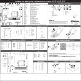
MW22-SE0 Motherboard Layout
DIMM_P0_A1
DIMM_P0_A0
DIMM_P0_B1
DIMM_P0_B0
CPU
1 2 3 4 5
6
7
8
9
101112131415161718
19
20
21
22
23
24 25 26

- 6 -
Item Code Description
1 HD_AUDIO Audio Connectors
2 R_USB3 USB3.0 Ports
3 USB3_LAN1 GbE Ethernet LAN Port (top) / USB3.0 Ports (bottom)
4 VGA_1 VGA Port
5 COM1 Serial Port
6 SYS_FAN1 System Fan Connector #1
7 P12V_AUX 8 Pin Power Connector (for CPU, DDR)
8 CASE_OPEN Case Open Intrusion Alert Header
9 SYS_FAN4 System Fan Connector #4
10 SYS_FAN3 System Fan Connector #3
11 ATX1 24 Pin Main Power Connector
12 CPU0_FAN CPU Fan Connector
13 SYS_FAN2 System Fan Connector #2
14 BAT Battery Socket
15 SATA_0_1 SATA III 6Gb/s Connectors
16 SATA_2_3 SATA III 6Gb/s Connectors
17 SATA4 SATA III 6Gb/s Connector #4
18 SATA5 SATA III 6Gb/s Connector #5
19 FP_1 Front Panel Header
20 F_USB3 USB 3.0 Connector
21 F_USB2 USB 2.0 Connector
22 M2_0 M.2 Slot (PCIe Gen3 x4, Support NGFF-2280, M-Key)
23 TPM TPM Module Connector
24 PCIE_1 PCI Express x8 Slot (Gen3 x4 Signal)
25 PCIE_2 PCI Express x16 Slot (Gen3 x16 Signal)
26 F_AUDIO Front Audio Header

- 7 -
Block Diagram

Hardware Installation - 8 -
1-1 Installation Precautions
The motherboard contains numerous delicate electronic circuits and components which can
become damaged as a result of electrostatic discharge (ESD). Prior to installation, carefully read
the user's manual and follow these procedures:
• Prior to installation, do not remove or break motherboard S/N (Serial Number) sticker or
warranty sticker provided by your dealer. These stickers are required for warranty validation.
• Always remove the AC power by unplugging the power cord from the power outlet before
installing or removing the motherboard or other hardware components.
• When connecting hardware components to the internal connectors on the motherboard,
make sure they are connected tightly and securely.
• When handling the motherboard, avoid touching any metal leads or connectors.
• It is best to wear an electrostatic discharge (ESD) wrist strap when handling electronic
components such as a motherboard, CPU or memory. If you do not have an ESD wrist
strap,keepyourhandsdryandrsttouchametalobjecttoeliminatestaticelectricity.
•
Prior to installing the motherboard, please have it on top of an antistatic pad or within an
electrostatic shielding container.
• Before unplugging the power supply cable from the motherboard, make sure the power
supply has been turned off.
• Before turning on the power, make sure the power supply voltage has been set according to
the local voltage standard.
• Before using the product, please verify that all cables and power connectors of your
hardware components are connected.
• To prevent damage to the motherboard, do not allow screws to come in contact with the
motherboard circuit or its components.
• Make sure there are no leftover screws or metal components placed on the motherboard or
within the computer casing.
• Do not place the computer system on an uneven surface
.
• Do not place the computer system in a high-temperature environment.
• Turning on the computer power during the installation process can lead to damage to
system components as well as physical harm to the user.
• If you are uncertain about any installation steps or have a problem related to the use of the
product,pleaseconsultacertiedcomputertechnician.
Chapter 1 Hardware Installation

- 9 - Hardware Installation
1-2 ProductSpecications
CPU Intel® Xeon® Processor E-2100/ E-2200 series
8th Gen. Intel Core™ i3/ Pentium®/ Celeron® Processors
Chipset Intel® C242 Express Chipset
Memory 4 x DIMM slots
Dual channel memory architecture
Supports 1.2V DDR4 memory
ECC UDIMM modules supported
Up to 64GB
Supported speeds: 2666/2400 MHz
Onboard
Graphics
Integrated in Aspeed® AST2510
2D Video Graphic Adapter with PCIe bus interface
1920x1200@60Hz 32bpp
Audio Realtek® ALC887 Controller
LAN 1 x GbE LAN port (Intel® I219LM)
Expansion Slots 1 x PCI Express x16 slot; running at Gen3 x16
1 x PCI Express x8 slot; running at Gen3 x4
1 x M.2 slot:
- M-key
- PCIe Gen3 x4 per slot
- Supports NGFF-2280/2260/2242 cards
- Intel® Optane™ Memory Ready
Storage Interface 6 x SATA III 6Gb/s connectors
RAID Intel® SATA RAID 0/1/10/5
Internal I/O
Connectors
1 x 24-pin ATX main power connector
1 x 8-pin ATX 12V power connector
6 x SATA III 6Gb/s ports
1 x CPU fan header
4 x System fan headers
1 x USB 3.0 header
1 x USB 2.0 header
1 x Front panel header
1 x TPM header
1 x Case Open header
Rear I/O
Connectors
1 x Serial port
1 x VGA port
1 x RJ45 ports
4 x USB 3.0 ports
3 x Audio Jacks
TPM 1 x TPM header

Hardware Installation - 10 -
Form Factor microATX
244mm W x 244mm D
GIGABYTE reserves the righttomake any changes to the productspecications and product-related
information without prior notice.

- 11 - Hardware Installation
DIMM_P0_A1
DIMM_P0_A0
DIMM_P0_B1
DIMM_P0_B0
CPU
1-3 Installing the CPU and CPU Cooler
1-3-1 Installing the CPU
A. Locate the alignment keys on the motherboard CPU socket and the notches on the CPU.
Read the following guidelines before you begin to install the CPU:
• Make sure that the motherboard supports the CPU.
• Always turn off the computer and unplug the power cord from the power outlet before installing
the CPU to prevent hardware damage.
• Locate the pin one of the CPU. The CPU cannot be inserted if oriented incorrectly. (Or you may
locate the notches on both sides of the CPU and alignment keys on the CPU socket.)
• Apply an even and thin layer of thermal grease on the surface of the CPU.
• Do not turn on the computer if the CPU cooler is not installed, otherwise overheating and
damage of the CPU may occur.
• SettheCPUhostfrequencyinaccordancewiththeCPUspecications.Itisnotrecommended
thatthesystembusfrequencybesetbeyondhardwarespecicationssinceitdoesnotmeetthe
standard requirements for the peripherals. If you wish to set the frequency beyond the standard
specifications, please do so according to your hardware specifications including the CPU,
graphics card, memory, hard drive, etc.
Notch
Alignment KeyAlignment Key
Notch
LGA1151 CPU
LGA1151 CPU Socket
Pin One Corner of the CPU Socket
Triangle Pin One Marking on the CPU

Hardware Installation - 12 -
Step 1:
Gently press the CPU socket lever handle down
andawayfromthesocketwithyournger.Then
completely lift the CPU socket lever and the metal
load plate will be lifted as well.
Step 3:
HoldtheCPUwithyourthumbandindexngers.
Align the CPU pin one (triangle marking) with the
pin one corner of the CPU socket (or you may
align the CPU notches with the socket alignment
keys). Gently insert the CPU into position.
Step 5:
Push the CPU socket lever back into its locked
position.
Step 4:
Once the CPU is properly inserted, use one
hand to hold the socket lever and use the other
to lightly replace the load plate. When replacing
the load plate, make sure the front end of the
load plate is under the shoulder screw.
NOTE:
Hold the CPU socket lever by the handle, not by
the lever base position.
Step 2:
Remove the CPU socket cover as shown. Hold
your index finger down on the rear grip of the
socket cover and use your thumb to lift up the
front edge (next to the "REMOVE" mark) and
then remove the cover. (DO NOT touch socket
contacts. To protect the CPU socket, always
replace the protective socket cover when the
CPU is not installed.)
B. Follow the steps below to correctly install the CPU into the motherboard CPU socket.
Before installing the CPU, make sure to turn off the computer and unplug the power cord from
the power outlet power plug to prevent any damage to prevent damage to the CPU.

- 13 - Hardware Installation
1-3-2 Installing the CPU Cooler
Follow the steps below to correctly install the CPU cooler on the motherboard. (The following procedure uses
Intel® boxed cooler as the example cooler.)
Use extreme care when removing the CPU cooler because the thermal grease/tape between the
CPU cooler and CPU may adhere to the CPU. Inadequately removing the CPU cooler may damage
the CPU.
Step 1:
Apply a thin, even layer of thermal paste onto
the surface of the installed CPU.
Male Push
Pin
Female
Push Pin
The Top
of Female
Push Pin
Direction of the
Arrow Sign on
the Male Push
Pin
Step 2:
Before installing the cooler, note the direction of
the arrow sign on the male push pin. (Turning
the push pin along the direction of the arrow is
for removing the cooler, and the opposite
direction is for installing it.)
Step 3:
Place the cooler atop the CPU, aligning the
four push pins through the pin holes on the
motherboard. Push down on the push pins
diagonally.
Step 4:
You should hear a "click" when pushing down
each push pin. Check that the Male and Female
pushpinsarejoinedclosely.(RefertoyourCPU
cooler installation manual for instructions on
installing the cooler.)
Step 5:
After the installation, check the back of the
motherboard. If the push pin is inserted as the
picture above shows, the installation is complete.
Step 6:
Finally, attach the power connector of the CPU
cooler to the CPU fan header (CPU_FAN) on the
motherboard.

Hardware Installation - 14 -
1-4 Installing the Memory
Read the following guidelines before you begin to install the memory:
• Make sure that the motherboard supports the memory. It is recommended to use memory of the
same capacity, brand, speed, and chips.
• Always turn off the computer and unplug the power cord from the power outlet before installing
the memory to prevent hardware damage.
• Memory modules have a foolproof design. A memory module can be installed in only one
direction. If you are unable to insert the memory, switch the direction.
1-4-1 Installing a Memory
Before installing a memory module, make sure to turn off the computer and unplug the
power cord from the power outlet to prevent damage to the memory module.
Be sure to install DDR4 UDIMMs on this motherboard.
Installation Step:
Step 1. Insert the UDIMM memory module vertically into the UDIMM slot, and push it down.
Step 2. Close the plastic clip at both edges of the UDIMM slots to lock the UDIMM module.
Note: For dual-channel operation, UDIMMs must be installed in matched pairs.
Step 3. Reverse the installation steps when you wish to remove the UDIMM module.
1
2
2
Type Ranks Per DIMM
and Data Width
Supported
Voltage
Speed (MT/s);
Slot Per Channel(SPC) and
DIMM Per Channel (DPC)
2 Slot Per Channel
1DPC 2DPC
UDIMM Unbuered
DDR4 ECC SR, DR 1.2V 2133/ 2400/ 2666 2133/ 2400/ 2666
UDIMM Unbuered
DDR4 non-ECC SR, DR 1.2V 2133/ 2400/ 2666 2133/ 2400/ 2666
• All channels in system run at the fastest common frequency.
• Mixing ECC and non-ECC UDIMMs anywhere on the plaorm is not supported.
• UDIMM 2666 two DIMMs per channel (2DPC) is supported when channel is populated with the same UDIMM memory
module.

- 15 - Hardware Installation
1-5 Installing the M.2 SSD Module
Follow the steps below to install a M.2 SSD module on your motherboard.
Step1. Insert the M.2 SSD module into the slot.
Step2. Secure it with the screw, tightening as necessary to fasten the M.2 SSD module in place.
2260
2242
2280
1
2

Hardware Installation - 16 -
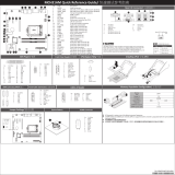
1-6 Back Panel Connectors
uSerial Port
Connects to serial-based mouse or data processing devices.
vVGA Port
The video-in port allows connection via video in, which can also apply to the video loop thru function.
wRJ-45 LAN Port
The Gigabit Ethernet LAN port provides Internet connection at up to 1 Gbps data rate. See the section
below for a description of the states of the LAN port LEDs.
xUSB 3.0 Port
The USB port supports the USB 3.0 specification. Use this port for USB devices such as a USB
keyboard/mouse,USBprinter,USBashdriveetc.
yLine In Jack (Blue)
ThedefaultLineinjack.Usethisaudiojackforlineindevicessuchasanopticaldrive,walkman,etc
zLine Out Jack (Green)
ThedefaultLineOutjack.Usethisaudiojackforaheadphoneor2-channelspeaker.Thisjackcanbe
usedtoconnectfrontspeakersina4/5.1/7.1-channelaudioconguration.
{Mic In (Pink)
ThedefaultMICInjack.AmicrophonecanbeconnectedtotheMICInjack.
Link/Activity LED
Connection/
Speed LED
LAN Port
• Whenremovingthecableconnectedtoabackpanelconnector,rstremovethecablefromyour
device and then remove it from the motherboard.
• When removing the cable, pull it straight out from the connector. Do not rock it side to side to
prevent an electrical short inside the cable connector.
Activity LED:Connection/Speed LED:
State Description
Yellow On 1 Gbps data rate
Green On 100 Mbps data rate
Off 10 Mbps data rate
State Description
Blinking Data transmission or receiving is occurring
Off No data transmission or receiving is occurring
3
5
6
7
1 2
4 4

- 17 - Hardware Installation
1-7 Internal Connectors
Read the following guidelines before connecting external devices:
• First make sure your devices are compliant with the connectors you wish to connect.
• Before installing the devices, be sure to turn off the devices and your computer. Unplug the power
cord from the power outlet to prevent damage to the devices.
• After installing the device and before turning on the computer, make sure the device cable has
been securely attached to the connector on the motherboard.
1) ATX 11) SYS_FAN4
2) ATX_12V 12) F_USB3
3) SATA0/ SATA1 13) F_USB2
4) SATA2/ SATA3 14) TPM
5) SATA4 15) FP_1
6) SATA5 16) F_AUDIO
7) CPU_FAN 17) BAT
8) SYS_FAN1
9) SYS_FAN2
10) SYS_FAN3
DIMM_P0_A1
DIMM_P0_A0
DIMM_P0_B1
DIMM_P0_B0
CPU
8
2
11
10 1 7 917 4 5 6
15
12
13
14
16
3

Hardware Installation - 18 -
DIMM_P0_A1
DIMM_P0_A0
DIMM_P0_B1
DIMM_P0_B0
CPU
1/2) ATX/ATX_12V (2x12 Main Power Connector and 2x4 12V Power Connector)
With the use of the power connector, the power supply can supply enough stable power to all the components
onthemotherboard.Beforeconnectingthepowerconnector,rstmakesurethepowersupplyisturnedoff
and all devices are properly installed. The power connector possesses a foolproof design. Connect the power
supply cable to the power connector in the correct orientation. The 12V power connector mainly supplies
power to the CPU. If the 12V power connector is not connected, the computer will not start.
To meet expansion requirements, it is recommended that a power supply that can withstand high
power consumption be used (500W or greater). If a power supply is used that does not provide the
required power, the result can lead to an unstable or unbootable system.
ATX
ATX_12V
12 1
13
24
PinNo. Denition
13 3.3V
14 -12V
15 GND
16 PS_ON
17 GND
18 GND
19 GND
20 -5V
21 +5V
22 +5V
23 +5V
24 GND
PinNo. Denition
1 3.3V
2 3.3V
3 GND
4 +5V
5 GND
6 +5V
7 GND
8 Power Good
9 5VSB
10 +12V
11 +12V
12 3.3V
8
5
4
1
PinNo. Denition
1 GND
2 GND
3 GND
4 GND
5 +12V
6 +12V
7 +12V
8 +12V

- 19 - Hardware Installation
DIMM_P0_A1
DIMM_P0_A0
DIMM_P0_B1
DIMM_P0_B0
CPU
DIMM_P0_A1
DIMM_P0_A0
DIMM_P0_B1
DIMM_P0_B0
CPU
3/4/5/6) SATA0/SATA1/SATA2/SATA3/SATA4/SATA5(SATA 6Gb/s Connectors)
The SATA connectors conform to SATA 6Gb/s standard and are compatible with SATA 3Gb/s standard. Each
SATA connector supports a single SATA device.
7
1
1
7
SATAIII_0
SATAIII_1
SATAIII_2
SATAIII_3
PinNo. Denition
1 GND
2 TXP
3 TXN
4 GND
5 RXN
6 RXP
7 GND
SATAIII_4
SATAIII_5
71
71
71
1
SATAIII_5
SATAIII_4
7
SATAIII_0
SATAIII_1
SATAIII_2
SATAIII_3
7/8/9/10/11) CPU_FAN/SYS_FAN1/SYS_FAN2/SYS_FAN3/SYS_FAN4
(CPU Fan/System Fan Headers)
The motherboard has one 4-pin CPU fan header (CPU_FAN), and two 4-pin (SYS_FAN) system fan headers.
Most fan headers possess a foolproof insertion design. When connecting a fan cable, be sure to connect
it in the correct orientation (the black connector wire is the ground wire). The motherboard supports CPU
fan speed control, which requires the use of a CPU fan with fan speed control design. For optimum heat
dissipation, it is recommended that a system fan be installed inside the chassis.
1
1
PinNo. Denition
1 GND
2 +12V
3 Sense
4 Speed Control
• Be sure to connect fan cables to the fan headers to prevent your CPU and system from
overheating. Overheating may result in damage to the CPU or the system may hang.
• Thesefanheadersarenotconfigurationjumperblocks.Donotplaceajumpercaponthe
headers.
SYS_FAN1
SYS_FAN3
SYS_FAN2 SYS_FAN4
CPU_FAN

Hardware Installation - 20 -
DIMM_P0_A1
DIMM_P0_A0
DIMM_P0_B1
DIMM_P0_B0
CPU
DIMM_P0_A1
DIMM_P0_A0
DIMM_P0_B1
DIMM_P0_B0
CPU
12/13) F_USB3/ F_USB2 (USB 3.0/ 2.0 Headers)
Theheaders conformto USB2.0/ 3.0 specication. Each USB header can provide two USB ports via an
optional USB bracket. For purchasing the optional USB bracket, please contact the local dealer.
F_USB2
PinNo. Denition
1 Power (5V)
2 Power (5V)
3 USB 7-
4 USB 11-
5 USB 7+
6 USB 11+
7 GND
8 GND
9 No Pin
10 No Connect
F_USB3
USB 2.0 Header
USB 3.0 Header
1110
201
Pin No. Denition Pin No. Denition
1 Power 11 USB6+
2 RXN1 12 USB6-
3 RXP1 13 GND
4 GND 14 TXP2
5 TXN1 15 TXN2-
6 TXP1 16 GND
7 GND 17 RXP2
8 USB5- 18 RXN2
9 USB5+ 19 Power
10 No Connect 20 No Pin
12
910
14) TPM (Trusted Platform Module Connector)
Trusted Platform Module (TPM) is an international standard for a secure cryptoprocessor, a dedicated
microcontroller designed to secure hardware through integrated cryptographic keys.
TPM
Pin No. Denition Pin No. Denition
1 CLK_24M_TPM 8 NC
2 +V3.3A 9 LAD_2
3 -PLTRST 10 No Pin
4 +V3.3S 11 LAD_3
5 LAD_0 12 GND
6 SERIRQ 13 LFRAME
7 LAD_1 14 GND
12
13 14
/