Page is loading ...

Therma-Stor II-6
Installation Instructions
1
www.thermastor.com • sales@thermastor.comToll-Free 1-800-533-7533
Read and Save These Instructions
SP-151A
Revised 5/12
Specifications subject to change without notice.
4201 Lien Rd. • Madison, WI 53704
For small usage:
1.
Introduction
The Therma-Stor II-6 is an insulated water storage tank and
refrigerant heat recovery device.
Therma-Stor Heat Recovery Water Heaters are intended
for inside installation unless an adequate cover is installed
to protect the unit from external moisture. Failure to
adequately protect the unit from external moisture will
result in premature condenser plate failure and void
the warranty.
2.
Choosing The Location For
The Therma-Stor II-6
The location for the Therma-Stor II-6 should be chosen
carefully. The following guidelines must be observed.
1. The Therma-Stor II-6 should be in a clean dry place as
close as possible to the compressors to minimize the
refrigerant line lengths.
2. It should be located with adequate clearance for ease
of installation and service.
3. It must be in an area that is protected from freezing.
4. It should be located where water would not damage
the surroundings or critical areas of the building if a
tting leaks. If a pitched oor to an open drain is not
available, a catch pan should be constructed. See
Figure 1.
5. Therma-Stor units must not be located where
ammable liquids are stored or where combustible
vapors might be ignited by the arc drawn inside the
thermostat when it cycles if one is used.
Caution: Failure to properly install the discharge line from
the safety relief valve could result in hot water spraying
on a person causing burns.
Table Of Contents
1. Introduction ........................................................................1
2. Choosing The Location For The Therma-Stor II-6 .........1
3. SpecicInformation .........................................................2
3.1 Construction Specications .....................................2
3.2 Operation ..................................................................2
3.3 Application Specications ........................................2
4. Installing the Therma-Stor II-6 and Plumbing ...............3
4.1 Control Valves (optional) ..........................................3
4.2 Valve Selection .........................................................4
5. InstallingtheRefrigerationSystem ...............................4
5.1 Installation Layout ....................................................4
5.2 Refrigerant ................................................................5
5.3 Refrigerant Lines ......................................................5
5.4 Refrigerant Connections ..........................................5
Serial No._________________________________________
Purchase Date_____________________________________
Customer Name____________________________________

2
www.thermastor.com • sales@thermastor.comToll-Free 1-800-533-7533
Specifications subject to change without notice.
3
. Specification Information
Features and Specifications
• Tank Dimensions
Diameter: 29 1/4”, Height: 62 1/4”, Weight: 400 lbs
• 114 gallon water capacity
• Rated for 450 psi refrigerant operating pressure
• 150 psi maximum operating water pressure
• Double wall protection between refrigerant and water
• Double normal water heating tank insulation
• UL Listed
• Approved for Canada
3.1 Construction Specifications
1. Vertical six circuit desuperheater plate welded and
expanded for internal refrigerant passage.
2. Refrigeration connections are 3/4” O.D. inlets,
and 5/8” O.D. outlets. (Six Sets)
3. Industrial glass lined hot water storage tank.
4. 1-3/4” foam-in-place urethane insulation.
5. Dual anode protection against corrosion for extended
tank life.
6. Water inlet and outlet are 1-1/4” male NPT.
7. 150 PSI and 210°F pressure/temperature relief valve.
8. Attractive enameled galvanized external wrapper.
9. 3/4” NPT midport for recirculation loop return or
medium temperature water out.
3.2 Operation
The Therma-Stor II-6 produces and stores hot water by
transferring refrigeration waste heat to cold water. This
cost-efcient alternative for producing hot water ts any
existing refrigeration system and improves the system’s
efciency at the same time. Hot water production depends
on the evaporator load, run time of the compressor, and
water usage.
3.3 Application Specification
The Therma-Stor II-6 can accommodate evaporating loads
of up to 4 tons per circuit when utilizing R-22 or R-502 and
2 tons per circuit on R-12. The individual circuits can be
joined at the inlets for larger loads. Considering the limited
condensing capacity, Therma-Stor’s are not intended to
substitute the need for air or water cooled condensers.
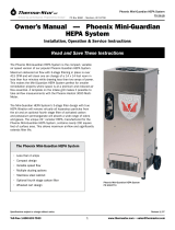
Therma-Stor plate
design, with rapid,
free-owing paths
for refrigerant gas,
promotes excellent
waste heat transfer
throughout the tank.
Urethane Foam Unsulations
Desuperheater Plate
Tank
Cover
1
3
4
5
2
6
6
7
8
9

3
www.thermastor.com • sales@thermastor.comToll-Free 1-800-533-7533
4.
Installing the Therma-Stor
II-6 and Plumbing
Many localities have enacted regulations, ordinances or
codes governing the installation of water heaters and heat
reclaimers. All local electrical, refrigeration and plumbing
codes must be complied with and the installation must be
accomplished only by qualied personnel.
1. After the location has been determined, the Therma-
Stor II-6 should be moved into position and leveled.
At this time reevaluate the working space allowed for
making the refrigeration connections and checking for
refrigeration leaks.
2. The cold water inlet is located at the bottom of the
tank. Provide a union, shut-off valve, and drain valve
for this connection. Refer to Figure 1 for typical
arrangements.
3. The hot water outlet is at the top of the tank. A
reducing tee and a combination pressure/temperature
relief valve are furnished with the Therma-Stor II-
6. These must be installed so the sensing element
extends inside the tank and the hot water discharge
is horizontal, as shown in Figure 3 and 4. Connect the
outlet of the relief valve to a suitable drain. The drain
pipe must pitch downward from the valve and should
be no smaller than the size of the outlet valve. The
end of the drain line should be close to the oor with
a 6” air gap. It must not be concealed and should be
protected from freezing. No valve of any type may be
installed between the relief valve and the tank or in the
drain line.
4. If additional water storage is desired an insulated
storage tank may be installed. This tank should be
set beside the Therma-Stor II-6. Connect the inlet and
outlet together with no check valves. See Figure 2.
4.1 Control Valves (Optional)
A water bleed valve is used to remove excessive energy from
the Therma-Stor II-6 to limit the water temperature. The
valve is normally open so water will ow from the Therma-
Stor II-6 when the valve is not energized. When the water
temperature rises to the thermostat set point, hot water
will be bled through the valve to dissipate more energy
than is being absorbed. The water temperature will drop to
the aquastat cut-in temperature and then the valve will be
activated stopping the ow. Only the amount of hot water
equal to the excess refrigerant energy will be bled off.
PRESSURE/TEMPERAT URE
RELIEF VALV EHOT
WATER
OUTLET
ANODES
MEDIUM
TEMPERAT URE
WATER
OUTLET
COLD
WATER
INTLET
SHUT-OFF
VALV E
3” MIN.
DRAIN
UNION
6” AIR GAP
DRAIN VALV E
34”
Figure 1: Therma-Stor II-6 plumbing
COLD
WATER IN
Therma-Stor
II-6
Insulated
Storage Tank
Figure 2: Plumbing the II-6 with an optional
storage tank.

4
www.thermastor.com • sales@thermastor.comToll-Free 1-800-533-7533
4.2 Valve Selection
1. The total connected refrigeration system capacity must
be less than 15 tons of evaporator load.
2. Provisions must be provided to safely dispose of the
bleed water.
3. Considerations should be made to accommodate a
ow rate of 40 gallons per hour. See Figure 3 for the
preferred installation.
4. Install an aquastat in the midport (See Figure 1) or
on the hot water piping to control the power to the
water solenoid.
5. To ll the Therma-Stor II-6, close the drain valve and
open a hot water tap to bleed the air from the tank
as it lls. Open the inlet water valve. Allow sufcient
time for the tank to ll as indicated by a steady ow of
water, then close the water tap and check for leaks.
6. If the optional valve is used, power will have to be
applied to the valve in order to close it while checking
for leaks.
Caution: To reduce the risk of excessive pressures and
temperatures in this water heater install temperature and
pressure protective equipment required by local codes but
not less than a combination temperature and pressure
relief valve certified by a nationally recognized testing
laboratory that maintains periodic testing laboratory
that maintains periodic inspection of production of listed
equipment of materials, as meeting the requirements of
Relief Valves and Automatic Gas Shutoff Devices for How
Water Supply Systems. ANSI Z21.22-1971. This valve
must be marked with a maximum set pressure not to
exceed the marked maximum working pressure of the
water heater. Install the valve into an opening provided
and marked for this purpose in the water heater and
orient it or provide tubing so that any discharge from
the valve will exit only within 6 inches above or at any
distance below the structural floor and cannot contact
any live electrical part. The discharge opening must not
be blocked or reduced in size under any circumstances.
5.
Installing the Refrigeration
System
5.1 Installation Layout
The Therma-Stor II-6 is designed for use in refrigeration
systems that have adequately sized air or water-cooled
condensers. The Therma-Stor II-6 should be installed
between the individual compressors and condensers. A
number of possible combinations are shown in gures
7-10.
Reducing Tee
Pressure/Temperature
Relief Valve
Therma-Stor II-6
Figure4:Pressure/temperaturereliefvalveinstallation
Bleed Water Outlet
Electric Line Voltage
Aquastat Located In
Medium Te mperature
Water Outlet (Optional)
Pressure and Temperature
Relief Valve
Hot Water Outlet
Water Bleed Outlet
Figure3:Therma-Storbleedvalvelocation(ifused)

5
www.thermastor.com • sales@thermastor.comToll-Free 1-800-533-7533
5.2 Refrigerant
The Therma-Stor II-6 desuperheater plate is designed for low
pressure drop. Each of the six sections of the plate will handle
up to 4 tons of R-22, R-502, or 2 tons of R-12. See Figure 6.
5.3 Refrigerant Lines
The compressor discharge line size is usually adequate for
normal installations. However, if lines are more than 20 feet
long, they should be sized for a maximum of 15 psig pressure
drop. (See ASHRAE piping tables.) Lines should be installed
to pitch toward the Therma-Stor II-6 and condenser, and to
drop down from the compressor discharge to form a 6” trap
to prevent oil and liquid refrigerant from accumulating on the
discharge valve plate.
When installing a Therma-Stor II-6 on an existing refrigeration
installation, extreme care must be used not to damage the
existing system. If the tubing must be routed into an existing
cabinet, the following precautions must be taken:
1. If cabinet openings or modications have to be made,
they must be accomplished in such a manner as not to
be detrimental to the cabinet. DO NOT cut into electrical
enclosures.
2. Do not route tubing through electrical enclosures or
cabinet section containing live metal parts. The tubing
must be properly supported and protected from sharp
edges and moving parts.
3. The tubing must be mechanically isolated from structural
building members.
5.4 Refrigerant Connections
The Therma-Stor II-6 line connections are made of copper
tubing.
Note: Be careful not to burn wrapper on insulation when
brazing refrigeration lines.
All joints should be checked for leaks and the lines
evacuated according to standard refrigeration practices.
Hot Water Out
Cold Water In
Compressor Condenser
Therma-Stor
II-6
Hot Water Out
Cold Water In
Therma-Stor
II-6
Hot Water Out
Cold Water In
Therma-Stor
II-6
Hot Water Out
Cold Water In
Therma-Stor
II-6
5/8” Outlet
1-1/4” Male NPT
Hot Water Outlet
3/4” Male NPT Recirculation
Loop Return Inlet
1-1/4” Male NPT
Cold Water Inlet
3/4” Inlet
29 1/4”
62 1/4”
Anodes
Anodes
Figure 6
Figure 7: Six compressors
and condensers
Figure 10: Three compresors
and condensers
Figure 9: Four compressors
and condensers
Figure 8: Five compresors
and condensers
See Figure 3
/