Page is loading ...

Owner’s Manual — HI-E Dry Vehere
Installation, Operation & Service Instructions
1
www.thermastor.com • sales@thermastor.comToll-Free 1-800-533-7533
Read and Save These Instructions
HI-E-Dry Vehere
Part Number 4025276
The HI-E DRY Vehere Pool & Spa Humidity Controller featuring FOCUS
TM
Technology is the industries
most efficient, durable and economic product for controlling moisture related problems associated
with indoor pools, whirlpools, hot tubs, and therapy/lap pools.
Vehere delivers comfort and solves:
• Chemical Odors • Foggy Windows • Mold & Mildew • High Humidity Level
• Condensate and Structural Moisture Problems
The Vehere with FOCUS
TM
Technology is...
Performance, Reliability & Comfort
The Vehere utilizes technology, which dramatically
improves performance, product reliability and comfort.
Performance - The Vehere’s innovative heat transfer
technology offers our customers...
“HI-Efficiency” - A dehumidifier resulting in a
compact refrigeration system requiring less electric
consumption.
This ensures the use of a standard 20 Amp electrical
outlet and LOW OPERATING COSTS!
“HI-Capacity” - Vehere’s passive heat transfer process
allows the removal of over 192 pounds of water per
day! (80°F, 60% RH). That’s two- three times more
water removal per kilowatt-hour of electricity than
conventional dehumidifiers.
Compact - The Vehere’s stainless steel enclosure is
corrosion resistant with a built-in fan for low noise
operation. The Vehere features a cabinet mounted
or remotely located control, easy-roll casters, and
the highest dehumidification capacity available in it’s
class.
Reliability - Our compact design uses less refrigerant,
which reduces our cost and improves reliability. The
Vehere’s HI-Efficiency operation can save thousands of
dollars annually.
Comfort - The Vehere provides airflows up to 540
CFM (cubic feet/minute) of Dry Air. This airflow helps
reduce foggy windows, mold, mildew and condensate...
all reduced to increase indoor occupant comfort!
Specifications subject to change without notice.
Revised 10/06
HI-E-Dry Vehere
PN 4025276

2
www.thermastor.com • sales@thermastor.comToll-Free 1-800-533-7533
1 Intended Application
The intended application for the Vehere is as a pool &
spa area humidity sensing controller applied either as a
free-standing device directly in the pool area or operated
remotely to provide dehumidified air to the pool or spa
area using optional ducting and remotely mounting the
humidity controller. The Vehere high efficiency dehumidifier
utilizes refrigeration to cool an incoming air stream below
its dewpoint as it passes through an evaporator coil. This
cooling results in the removal of moisture (latent heat).
The cooled and dried air is used to pre-cool the incoming
air stream resulting in up to a 200 percent increase in
overall efficiency.
2 Specifications
Model: HI-E Dry Vehere (4025276)
Electrical: 110-120 VAC, 12.0 Amps, grounded
(7’ power cord included)
Compressor LRA: 64.5 Amps
Capacity: 184 pints/day @ 80°F, 60% RH
Air Flow: 540 CFM without external ducting
510 CFM @ .15 IWG external static
Refrigerant Charge: 2 lbs., 13 oz. R-22
Optional Duct Connections: 12” round inlet & outlet
Size (w/o duct collars): 36.5” Long x 19” Wide x 40” High
Weight: 180 lbs.
Controller Accuracy: +/- 5% RH @ 72°F
Capacities
The Vehere is designed to control humidity for indoor
pool (spa, hot tub) areas. It consists of a controller,
dehumidifying cooling system, filter, fan and delivers the
following dehumidification capacities:
Air Temp/Relative Humidity Lbs./Hour Lbs./Day
80°F/80%RH 10.34 248
82°F/60%RH* 8.336 200
80°F/60%RH 8.04 193
60°F/80%RH 7.17 172
Air Temp/Relative Humidity Pints/Hour Pints/Day
80°F/80%RH 9.92 238
82°F/60%RH* 7.95 191
80°F/60%RH 7.71 184
60°F/80%RH 6.67 160
Air Temp/Relative Humidity BTUs/Hour KWH/Day
(derived)
80°F/80%RH 15313 37.1
82°F/60%RH* 13114 35.3
80°F/60%RH 12680 34.3
60°F/80%RH 10869 27.5
*ASHRAE Recommended Conditions
Read these installation, operation and service
instructions carefully before installing and using this
unit. Proper adherence to these instructions is essential
to obtain maximum benefit from your Vehere pool & spa
humidity controller.
• If used near a pool or spa, be certain there is NO
chance the unit could roll into the water or be
splashed and that it is plugged into a GROUND FAULT
INTERRUPTER.
• DO NOT use the Vehere as a bench or table.
• Avoid discharging the exhaust directly at people or
pets.
Table of Contents
1. Intended Application for Vehere ..............................1
2. Specifications & Capacities ....................................1
2.1 Vehere Diagram...............................................2
3. Installation ............................................................2
3.1 Location .........................................................2
3.1A Improper Installation .................................2
3.1B In humid area, no ducting .........................3
3.1C In humid area, duct inlet and/or outlet .......4
3.1D In remote area, duct inlet & outlet .............4
3.2 Mounting the Humidity Sensor/Controller ..........5
3.3 Electrical Requirements ...................................5
3.4 Condensate Removal .......................................5
3.5 Ducting ...........................................................5
3.5A Ducting kit ...............................................5
3.5B Ducting for Dehumidification .....................6
4. Operation .............................................................6
4.1 Humidity Control..............................................6
4.2 Humidity Control Adjustment ............................6
4.3 Fan Switch ......................................................6
4.4 Automatic Defrost Control ................................6
4.5 Automatic Low Pressure Control .......................6
5. Ventilation ............................................................7
5.1 Ventilation Recommendations ..........................7
6. Maintenance .........................................................7
6.1 Air Filter ..........................................................7
7. Service .................................................................7
7.1 Technical Description .......................................7
7.2 Troubleshooting ...............................................7
7.3 Refrigerant Charging ........................................8
7.4 Blower Replacement ........................................8
7.5 Low Pressure Control .......................................8
7.6 Relay ..............................................................8
8. Vehere Accessories ................................................8
9. Vehere Electrical Wiring Diagram ............................9
10. Service Parts .......................................................10
11. Warranty .............................................................11

3
www.thermastor.com • sales@thermastor.comToll-Free 1-800-533-7533
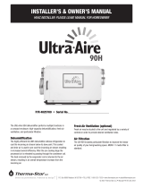
2.1 Vehere Diagram
A - Air Intake
B - Humidity Sensor/Control
C - Filters
D - Air Exhaust
E - Fan Switch
F - Power Cord
G - Drain Hose
Figure 1: Vehere diagram.
36.5”
A
C
C
B
E
D
G
F
40”
19”
Vehere Pool & Spa
Humidity Controller
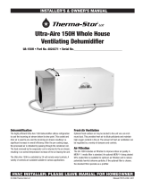
Figure 2: Installation clearance requirements
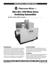
Figure 3: Installation in humid area with no ducting
3 Installation Options
3.1 Location
The Vehere can be installed in a variety of locations to meet
the owner’s needs; other considerations include:
1. Providing access to a 115 VAC power outlet (7’ power
cord is provided).
2. Locating near a floor or other suitable drain (4’ drain
hose included).
3.1A Improper Installation
Do not install the Vehere with the exhaust of the unit within
3’ of a wall or obstruction. Do not place the unit near open
water. (See Fig. 2)
3.1B In Humid Area, No Ducting
The simplest installation is to place the Vehere in the pool
area with no ducting. The Vehere must be at least 3’ from
walls and other air obstructions, at the return and supply
sides of the Vehere. (See Figure 3)

4
www.thermastor.com • sales@thermastor.comToll-Free 1-800-533-7533
3.1D In Remote Area, Duct Inlet & Outlet
It is often desirable, to install the Vehere in an adjacent
equipment room or unfinished area. Air is then transferred
between the humid room and the unit via ducting.
Remotely mount the Vehere humidity control in the humid
room and wire to the Vehere. Local electrical codes must
be followed when wiring the control. Refer to the “Mounting
the Humidity Sensor/Controller” section which follows.
(See Fig. 5)
3.1C In Humid Area, Duct Inlet and/or Outlet
If the pool room is very large or has high ceilings,
dehumidification can be improved by adding an inlet
and/or outlet duct to circulate and destratify stagnant
areas. Add inlet or outlet ducting to create flow across the
area’s greatest length. For areas with ceilings higher than
12’, use an inlet duct to draw warm, moist air from near
the ceiling. See section 4.5 for attaching duct collars &
ducting. (See Fig. 4)
Dehumidistats
for Quiet-Vent and
remote Vehere
Direct Warm & Dry Air
Toward Window Glass
Quiet-V
ent
Optional Quiet-Vent
Exhaust Ventilator
Low = 165 CFM
high = 290 CFM
Vehere Pool & Spa
Humidity Controller
Figure 4: Installation in humid area with ducting.
Quiet-V
ent
Dehumidistats
for Quiet-Vent and
remote Vehere
Direct Warm & Dry Air
Toward Window Glass
Optional Quiet-Vent
Exhaust Ventilator
Low = 165 CFM
high = 290 CFM
Vehere Pool & Spa
Humidity Controller
Figure 5: Installation in remote area with ducting.

5
www.thermastor.com • sales@thermastor.comToll-Free 1-800-533-7533
3.2 Mounting The Remote Humidity Sensor/
Controller
If the Vehere is to be located in a remote location outside
the pool or spa area, mounting of the humidity sensor in
the space to be conditioned is necessary. If the humidity
sensor is not located in the conditioned space, the Vehere
will not operate properly.
IMPORTANT: Locate the humidity element on an inside wall, free
from drafts, out of direct sunlight, and where the element is not
exposed to excessive vibration. Be careful not to drop the unit.
Mount the wall mount element at a height of 4 to 6 feet (1.2 to
1.8 m) above the floor.
To mount the HI-E DRY Vehere dehumidistat on a wall
for remote application, first remove the cover from the
controller by lifting the side of the controller cover over the
catch tabs on both sides. The cover comes off easily.
Hold the unit to the surface you would like to mount it on.
You will need to mark the locations for two screw holes
and one square knockout to accommodate wires and the
devices wire guard. The wire-guard tabs fit inside the wall.
(See Fig. 6, 7)
Once marked, drill a 1/8” hole for each mounting screw
location and tap the provided anchor mount into the hole.
Use the provided screws to then mount the humidity
control to the wall. Route the wiring through the hole you
have created and connect wires according to the directions
found in this manual. Replace plastic housing.
3.3 Electrical Requirements
The Vehere can be plugged into any grounded 20 Amp
circuit. At 80°F, 60% RH, it draws 11.6 Amps. A dedicated
20 Amp circuit is recommended.
3.4 Condensate Removal
Condensate drains by gravity via the clear hose extending
from the unit. Route the 4’ drain hose to a floor drain.
Use care to keep the hose as flat to the floor as possible.
Keep the hose away from walk ways if possible. Excessive
humps or kinks will prevent proper drainage. If the Vehere
is located too far from a floor drain for the attached hose
to reach, inexpensive 1/2” PVC pipe can be used to
extend it. It is commonly available in 10’ lengths from
building supply, plumbing and hardware stores. It will slide
tightly inside the end of the drain hose. If more than one
length of pipe is required, they can be joined with a short
piece cut from the end of the drain hose.
3.5 Ducting
3.5A Ducting kit
The factory installation kit includes two twelve-inch collars
to allow ducting to be attached to the inlet and outlet of
the Vehere. The 12” collar with three tabs can be attached
via the holes provided in the front of the unit, and the 12”
flanged collar can be affixed to the top opening. S (See
Fig. 8)
Figure 6: Mark mounting
holes as indicated by arrows.
Figure 7: Control
connection wires.
Figure 8: Tabbed duct collar is installed around the ex-
haust outlet. The flanged duct collar is installed around
the intake opening.
Tabbed duct collar
Flanged duct
collar

6
www.thermastor.com • sales@thermastor.comToll-Free 1-800-533-7533
3.5B Ducting for Dehumidification
Ducting the Vehere as mentioned requires consideration of
the following points:
The Vehere will require a single 12” round or equivalent
dedicated return from the pool room. The Vehere
supply can be dedicated or tapped into a forced air
system supply. A check damper should be used at the
connections.
The warm/dry supply air should be washed over the
windows at multiple drops for best results. Grills and
diffusers or duct ends must not excessively restrict airflow.
Round flex duct can be purchased by ordering the following
part numbers from the factory:
4020647 4” Flex Duct 4” x 25’
4020128 6” Flex Duct 6” x 25’
4020177 8” Flex Duct 8” x 25’
4022126 10” Flex Duct 10” x 25’
4024750 12” Flex Duct 12” x 25’
4 Operation
4.1 Humidity Sensor/Control
The control is an adjustable switch that closes when the
relative humidity of the air it senses rises to the dial set
point. It opens when the RH drops 4 to 6% below the set
point. (See Fig. 9)
4.2 Humidity Control Adjustment
The dehumidifier will run until the desired relative humidity
(RH) matches the control dial setting.
The humidity controller has been designed for simplicity
of use. It is marked “Low”, “Normal” and “High.” These
operational settings represent the amount of humidity in
the air. Setting the control to the “Low” setting will result
in a lower relative humidity than the “High” setting. We
recommend setting the controller at the “Normal” setting
and then adjusting as you see fit, moving the controller
toward “Low” to lower the humidity and toward “High” to
increase the level of humidity in your pool or spa area.
Figure 9: Vehere
humidity sensor/
controller.
Approximate Humidity Levels Per Setting
“Low” 35% to 45% Relative Humidity
“Normal” 45% to 55% Relative Humidity (Recommended)
“High” 55% to 65% Relative Humidity
A quality humidity meter is recommended to accurately
monitor humidity levels. For a quote on a quality humidity
meter, contact customer service at 1-800-533-7533.
4.3 Fan Switch
Turning the fan switch ON will cause the unit’s internal
blower to run continuously, whether the unit is
dehumidifying or not. This function is desirable if the unit
is used for air circulation or fresh air ventilation.
(See Fig. 10)
4.4 Automatic Defrost Control
When the Vehere is used in a cool area, frost may form on
the cooling coil as it dehumidifies. When frost forms, our
automatic defrost thermostat will periodically turn off the
compressor while allowing the blower to run. The blower
draws air through the cooling coil and melts the frost.
The defrost cycle is automatic and designed for optimum
performance above 50°F.
4.5 Automatic Low Pressure Control
If the low side refrigerant pressure drops to 15 PSIG, the
low pressure control opens and shuts off the compressor
and blower. It is an automatic reset that will close when
the pressure rises to 35 PSIG. This feature prevents
damage to the compressor. It may also open if the unit is
used in a cool area (below 50°F) or stored below 40°F and
then started. Under these conditions, the unit will restart
within several minutes.
Figure 10: Vehere fan switch.

7
www.thermastor.com • sales@thermastor.comToll-Free 1-800-533-7533
5 Ventilation
WARNING: Do not use open combustion heating appliances
(unless equipped with power exhaust) in a pool room equipped
with exhaust fans. Under certain conditions these exhaust fans
may cause the backdrafting of toxic combustion by-products
which are hazardous to human health and could cause death.
We strongly recommend using only closed combustion heating
appliances.
5.1 Ventilation Recommendations
Ventilation is an important element of pool and spa
dehumidification. A negative (exhaust) pressure ventilation
system should be used. This ventilation system is
operated and installed independently of the Vehere unit
and keeps the concentrations of corrosive pool chemicals
to a minimum and assists in keeping moisture from
penetrating the rest of the structure. Ventilation should be
sized to all local codes. It is best if the ventilation is a net
negative in pressure.
6 Maintenance
6.1 Air Filter
The Vehere is equipped with two, 2” thick, pleated fabric
air filters that must be checked regularly. Operating the
unit with dirty filters will reduce the humidity controller’s
capacity and efficiency and may cause the compressor
to cycle off and on unnecessarily on the defrost control.
The filters can generally be vacuumed clean several times
before needing replacement. Replacement filters can be
ordered from the factory.
7 Service
WARNING: Only qualified service people should service this unit.
The Vehere has a high-pressure refrigerant system and high
voltage circuitry. This could present a hazard which could result
in death, serious bodily injury, and/or property damage. Only
qualified service people should service this unit.
7.1 Technical Description
The Vehere uses a refrigeration system to remove heat
and moisture from incoming air, and add heat to the
air it discharges. Hot, high-pressure refrigerant gas is
routed from the compressor to the condenser coil. The
refrigerant is cooled and condensed by giving up its heat
to the air it discharges from the unit. The refrigerant liquid
then passes through two capillary tubes, which cause
the refrigerant pressure and temperature to drop. It next
enters the evaporator coil where it absorbs heat from the
incoming air and evaporates.
The evaporator operates in a flooded condition, which
means it should always be full of liquid refrigerant during
normal operation. A flooded evaporator should maintain
constant pressure and temperature across the entire coil,
from inlet to outlet. A mixture of gas and liquid refrigerant
enter the accumulator after leaving the evaporator coil. The
accumulator prevents any liquid refrigerant from reaching
the compressor. The compressor removes the cool
refrigerant gas from the accumulator and compresses it to
a high pressure and temperature to repeat the process.
7.2 Troubleshooting
No dehumidification, neither blower nor compressor run
with fan switch OFF.
1. Unit unplugged or no power to outlet.
2. Humidity control set too high or defective
3. Loose connection in internal wiring.
4. Open low pressure control
Dehumidification, blower runs continuously but compressor
only runs sporadically with fan switch OFF.
1. Unit is in defrost cycle
2. Defrost thermostat defective or loose
3. Loose connection in compressor circuit
4. Defective compressor overload
5. Defective compressor
6. Defective relay
No dehumidification. Blower runs but compressor does not
with fan switch OFF.
1. Bad connection in compressor circuit
2. Defective compressor capacitor
3. Defective compressor overload
4. Defective compressor
5. Defective relay
Blower does not run. Compressor runs briefly but cycles on
& off.
1. Loose connection in blower circuit
2. Obstruction prevents impeller rotation
3. Defective blower
Unit removes some water but not as much as expected.
1. Air temperature and/or humidity have dropped.
2. Humidity meter and/or thermometer used are out of
calibration.
3. Unit has entered defrost cycle
4. Air filter dirty
5. Defective defrost thermostat
6. Low refrigerant charge
7. Air leak such as loose cover.
8. Defective compressor
9. Restrictive ducting

8
www.thermastor.com • sales@thermastor.comToll-Free 1-800-533-7533
Evaporator coil frosted continuously, low dehumidifying
capacity.
1. Defrost thermostat loose or defective
2. Low refrigerant charge
3. Dirty air filters or airflow restricted.
7.3 Refrigerant Charging
WARNING: Only qualified service people should service this unit.
The Vehere has a high-pressure refrigerant system and high
voltage circuitry. This could present a hazard which could result
in death, serious bodily injury, and/or property damage. Only
qualified service people should service this unit.
If the refrigerant charge is lost due to service or a leak, a
new charge must be accurately weighed in. If any of the
old charge is left in the system, it must be removed before
weighing in the new charge. Refer to the unit nameplate
for the correct charge weight and refrigerant type. Add the
refrigerant through the low side service port. (See Fig. 11)
7.4 Blower Replacement
The blower has a PSC motor internal thermal overload
protection. If defective, the complete assembly must be
replaced.
1. Unplug the power cord.
2. Remove the cabinet front.
3. If an outlet duct is connected to the unit, remove it.
4. Disconnect the blower leads: white from the
compressor run capacitor, and black connected to the
fan switch.
5. Remove the nuts & bolts holding the blower outlet
flange to the cabinet end and remove the blower.
6. Reassembling with the new blower is the above
procedure reversed.
7.5 Low Pressure Control
If the low side refrigerant pressure drops to 15 PSIG, the
low pressure control opens and shuts off the compressor
and blower. It is automatically reset. It will close when the
refrigerant pressure rises to 35 PSIG. Its primary function
is to prevent damage to the compressor if a leak develops
in the refrigeration system. It may also open if the unit is
A) used in a cool area (below 50°F) and the defrost timer
is not adjusted or B) stored where it is below 40°F and
then started. Under these conditions, the unit will restart
within several minutes. Until the unit warms up, it may
cycle several times.
7.6 Relay
The contacts of the single pole, single throw relay
complete the power circuit to the compressor. The
contacts are closed when power is provided to the relay
coil via the control circuit. The control circuit includes the
humidity control, low pressure control, defrost thermostat
and timer.
8 Vehere Accessories
Part No. Item
4025283 Vehere Remote Humidity Sensor/Control
4022646 Indoor/Outdoor Relative Humidity Meter
4024934 Deluxe Indoor Relative Humidity Meter
4021749 Filter (2 Filters Required)
4023539 Collar, Duct, 12”, Galv. (intake)
4023603 Collar Assy, Duct, 12”, Galv. (exhaust)
Optional Ventilator
4019663 Quiet-Vent Exhaust Ventilator
Figure 11: Low side service port.

9
www.thermastor.com • sales@thermastor.comToll-Free 1-800-533-7533
9 Vehere Electrical Wiring
Figure 12: Vehere wiring diagram.

10
www.thermastor.com • sales@thermastor.comToll-Free 1-800-533-7533
10 Service Parts
ITEM PART NO. QTY. DESCRIPTION
1 4021083 1 Blower with Capacitor
2 4022740 1 Capacitor, Run, 30MFD, 370v
3 4017777 2 Capillary Tubes, .059” ID x 32” long
4 4023604 4 Caster, 2”, Plastic, Swivel
5 4023533 1 Coil, Condenser
6 4023534 1 Coil, Evaporator
7 4025738 1 Compressor Service Assembly—includes compressor, capacitor and overload
4022595 1 Compressor Overload
8 4022219 1 Control, Low Pressure
9 4025278 1 Cord & Wire Harness
10 4021470 1 Defrost Thermostat
4021648 1 Defrost Thermostat Mounting Clip
11 4021799 2 Filter, Air (2” X 16” X 16”), (Grainger P/N 6B958)
12 4025087 1 Filter/Drier
13 4017152 1 Hose, Drain, .38” x 20’ long
14 4021689 1 Hose, Drain Pan, .56” ID x 16” long (not shown)
15 4025283 1 Humidity Controller, Cabinet Mounted
4021495 1 Knob
16 1096010 6 Machine Screw, Stainless Steel, ¼-20 X 1” (for Front Cover)
17 4022484 1 Relay, SPDT, 24 Volt
18 4023549 6 Self-Retaining Nut, ¼-20
19 4020988 1 Service Valve Assembly w/ Core & Cap
20 4025560 1 Switch, SPDT, On-Off, for Fan
21 4021818 1 Accumulator
4023609 1 Wiring Diagram (NS)
4022487 1 24 Volt Transformer

11
www.thermastor.com • sales@thermastor.comToll-Free 1-800-533-7533
HI-E DRY Vehere Dehumidifier Limited Warranty
Warrantor:
Therma-Stor LLC
PO Box 8680
Madison, WI 53708
Telephone: 1-800-533-7533
Warranty: This warranty covers the HI-E Dry Vehere.
Year One - 100% parts and labor (all components)
Year(s) Two through Five - The condenser, evaporator and compressor of the HI-E Dry Vehere will
operate free of any defects in material or will repair or replace the defective part(s).
If a defect in materials or workmanship occurs within the warranty period, Therma-Stor LLC will
repair or replace the defect.
User Responsibilities: Warranty service must be performed by a servicer authorized by Therma-
Stor LLC. To obtain warranty service you must obtain a return material authorization (RMA). To
obtain an RMA you must present proof of purchase or (lease), by use of a warranty card, original
sales receipt or other reasonable and reliable means.
To obtain an RMA call Therma-Stor LLC at the above number and ask for the Therma-Stor LLC
Service Department, which will then issue an RMA# and arrange for, at our option, either repair
or replacement.
Freight: Freight to and from the servicer is the responsibility of the end-user. The end-user is
responsible for normal care and proper return packaging.
Limitations and Exclusions: This warranty does not cover any defect, malfunction, etc.
resulting from misuse, abuse, lack of normal care, corrosion, freezing, tampering, modification,
unauthorized or improper repair or installation, accident, acts of nature or any other cause
beyond Therma-Stor LLC’s reasonable control.
If any HI-E Dry Vehere part is repaired or replaced, the new part shall be warranted for the
balance of original warranty (but all warranty periods will be extended by the period of time, if any,
that the Vehere is out of service while awaiting covered warranty service).
Warranty service will be performed during normal working hours.
UPON THE EXPIRATION OF THE WRITTEN WARRANTY APPLICABLE TO THE HI-E DRY VEHERE OR
ANY PART THEREOF, ALL OTHER WARRANTIES IMPLIED BY LAW, INCLUDING MERCHANTABILITY
AND FITNESS FOR A PARTICULAR PURPOSE, SHALL ALSO EXPIRE. ALL WARRANTIES MADE
BY THERMA-STOR LLC ARE SET FORTH HEREIN, AND NO CLAIM MAY BE MADE AGAINST
THERMA-STOR BASED ON ANY ORAL WARRANTY. IN NO EVENT SHALL THERMA-STOR LLC, IN
CONNECTION WITH THE SALE, INSTALLATION, USE, REPAIR OR REPLACEMENT OF ANY HI-E DRY
VEHERE OR PART THEREOF BE LIABLE UNDER ANY LEGAL THEORY FOR ANY SPECIAL, INDIRECT
OR CONSEQUENTIAL DAMAGES INCLUDING WITHOUT LIMITATION WATER DAMAGE (THE END
USER SHOULD TAKE PRECAUTIONS AGAINST SAME), LOST PROFITS, DELAY, OR LOSS OF USE OR
DAMAGE TO ANY REAL OR PERSONAL PROPERTY.
Some states do not allow limitations on how long an implied warranty lasts, and some do not
allow the exclusion or limitation of incidental or consequential damages, so one or both of these
limitations may not apply to you.
Legal Rights: This warranty gives you specific legal rights, and you may also have other rights
which vary from state to state.
/