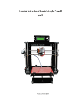
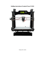
MBot CUBE Assembly Instructions Manual

  • Hello! I've carefully reviewed the assembly instructions for the Cube 3D printer. This document provides detailed steps for assembling your printer, covering everything from frame construction to electronics installation, and leveling the build plate. I'm here to assist you with any questions you may have regarding the assembly process, features or other operations of your printer.
  • What should I do if any accessories are missing or damaged?
    How do I get support for assembling or other queries?
    What software do I use to prepare my files for printing?
    What should I do before printing?
Welcome to use MBot Cube 3D Printer
Please check all the accessories one by one in the package, any missing or
damage, Please contact sales representative within 7days of receiving the MBot
cube kit.
Have any problem during assembling or other query contact us at
A3
A6
A1 A 2
A4
A7
A9
A8
A5
panel
tray
Brass barrel
nut
nut
Washer
工具包
1 2 3
J
Tool box
Control button planel cable
L
Control button panel
protector
Cable wrap
er
G 2 m3 x8m m
6PCS
G 3 m3 x12 mm
4PCS
G 7 m3 x30 mm
4P CS
G 9 m3
9PCS
G 12 m3 C5 m3x7x20mm
4P CS 4P CS
G 4 m3 x16 mm
1PCS
A6 I6
G3
X2
G15
G4
X4
G7
X4
G2
X2
I7
G3
X2
G2
X4
G9
X2
G9
X2
A9 I1
C5
X4
A8
G12
X4
C1
X3
Assemble all the
electronics
components and
C1 stick to the
correct position.
A8
G9
X
G3
X
A8 A1
G9
X
G3
X
C3
C3
I2
G3
X2
G3
X4
G9
X2
G9
X4
I3
C7
X4
G6
X4
C7
X2
G 9
6PCS
G 3 m 3x1 2 mm
PCS6
G 15 m3
4P CS
i
2
2
2
2
Y Axis Assembly
G3 X4
G9 X2
I4
C6 X2
G5 X2
G3
G9 X4
A8
C4
C3
C2
G3
X轴限位开关
G12
G12
C2
A4
G9
G 3 m3 x12 mm
6P CS
G 5 m3 x20 mm
2P CS
G 9
8P CS
G 1 2 m 3
PCS2
I4
G9
C6
X2
X2
C5
X2
A2
G12
X4
C5
X4
I5
F5
A5
G7
X4
G 7 m 3x3 0mm
4P CS
G 9 m 3
2P CS
G 3 m 3x1 2mm
2P CS
G 1 2 m3
4P CS
C6 3x7x12
2PCS
C6 3x7x20
4PCS
Attention:
Don’ t fasten screw on
the motor too tight.
G8 2
X
G14 3
X
G11 3X
F7
G10 3X
F8
G 8
3P CS
m5 x35 mm G 1 4
3P CS
G 1
PCS3
0 m5
F3
X2
Z Axis and Build
platlorm Assembly
Insert (F7) the build
platlorm into threaded Z
axis rod and ratare the
threaded rod
anti-clockwise untill build
platlorm reach bottom.
B1
F2
X2
E1
B1
Left Right
X2
X2
X2
X2
panel
10 11 12 13
14
17
18
21
20
15 16
19
按键面板和液晶屏的连接线H2,连接时两端接口相反即可。
Check the direction of the TP1 and
TP2 at Chip on the motherboard. TP2 should be facing towards
the stepper motor jack. Wrong assemble may destroy chips
and motherboard.
PS:H2 cable each end jacks are same, but it should be
connecting each other jack in opposite directions on Control
button and the LCD Screen.
A6 I6
G3
X2
G3
X2
G2
X4
G9
X2
G9
X2
A8
G12
X4
G12
X2
http://www.mbot3d.cn 购买与技术服务电话:400 004 1266 0571-88021266
Add:杭州市高新区(滨江)建业路511号华业大厦14楼 邮编:310052
http://www.mbot3d.com www.magicfirm.com
Tel: 400 004 1266 +86 571 8802 1266 ( UTC+8 9:30-18:00 work time)
14th Floor,Block A,Huaye Building,511 Jian Ye Road,Binjiang District,310052,Hangzhou
/