Page is loading ...

ATyS C55/65
QUICK START
549782C
1
2
201 202
101
Aux. 1
Aux. 2
102
312313 314315 316317 63A64A 24 14 04 13
11 14 12 21 24 22 31 34 32 41 44 42 51 54 52 61 64 62
71 72 73 74 75 76 70 82 81
L1 L2 L3 N L1 L2 L3 N I1 I2 I3 IN GND GND
L1
L2
L3
N
L1
L2
L3
N
230/400 V 230/400 V
OUT 1 OUT 2 OUT 3 OUT 4 OUT 5OUT 6
USB
CT
IN1 IN2 IN3 IN4 IN5IN6 COM+ -
RS485SOURCE 1
1A type gG 1A type gG
4A type gG
CTR
ATyS
AVAL
OFF II I0C
II I0C
4A type gG
DIGIWARE
DIGIWARE
INPUTS
SOURCE 2
NC
-+
IEC 61010
Non contractual document.
Subject to change without notice.
Preliminary operations
Check the following upon delivery and after removal of
thepackaging:
Packaging and contents are in good condition.
The product reference corresponds to the order.
Contents should include:
Qty 1 x C55 or C65 Controller
Qty 1 x Controller IP65 gasket (C65 only)
Qty 4x door mounting screws
Qty 4x backplate mounting feet
Warning
Risk of electrocution, burns or injury to persons and /
ordamage to equipment.
This Quick Start is intended for personnel trained in
theinstallation and commissioning of this product. For
further details refer to the product instruction manual
available onthe SOCOMEC website.
This product must always be installed and commissioned
by qualified and approved personnel.
Maintenance and servicing operations should be
performed by trained and authorized personnel.
Do not handle any control or power cables connected
tothe product when voltage may be, or may become
present on the product, directly through the mains or
indirectly through external circuits.
Always use an appropriate voltage detection device
toconfirm the absence of voltage.
Ensure that no metal objects are allowed to fall in
thecabinet (risk of electrical arcing).
Failure to observe good engineering practices as well as
tofollow these safety instructions may expose the user and
others to serious injury or death.
Risk of damaging the device
In case the product is dropped or damaged in any way
itis recommended to replace the complete product.
Installation standards must be respected.
Accessories
Digiware I/O 10 (ref. 48290140)
Gateway M70 (ref. 48290222)
Controller 24 VDC aux power supply (6W minimum type
SELV) mandatory with I/0 10 Modules
* For further details refer to the product instruction manual under
chapter “Spares and Accessories”
Spares
Connector kit (ref. 16090002)
Controller backplate mounting feet (ref. 16090005)
Controller door mounting screws (ref. 16090004)
Controller IP65 gasket (ref. 16090001) (C55/65)
- Short press on this button to go back one level.
- Long press to access the menus.
- Short press on this button to cycle the dashboards starting by the dashboard set as favorite.
- Long press to select current dashboard as favorite.
EN
ATS Controller
STEP 1
Installation
STEP 2
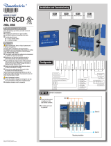
Connections
STEP 3
Configuration
STEP 4
Visualization
STEP 5
Menus &
programming
www.socomec.com
To download, brochures, catalogues
and technical manuals
STEP 4
STEP 5
Visualization
Menus & programming
Installation and Commissioning
Connection diagram with ATYS d
CORPORATE HQ CONTACT:
SOCOMEC SAS,
1-4 RUE DE WESTHOUSE,
67235 BENFELD, FRANCE
*C65 only
*C65 only
PARAMETERS
NETWORK
LOAD
DISPLAY
TIMERS
I/0
COMMUNICATION
ALARMS
PASSWORD
WIZARD
NETWORK
AUTODETECT
SETUP
APPLICATION
OP RANGE S1
OP RANGE S2
I/O
INPUTS
OUTPUTS
EXTERNAL I/O DETECTION
EXTERNAL I/O CONFIG
COMMUNICATIONS
MODBUS ADDRESS
RS485 MODBUS
DIGIBUS COMM
DIGIWARE MODE
ALARMS
MEASURE ALARMS CONFIG
MAINTENANCE ALARMS CONFIG
COMBINATION ALARMS CONFIG
LOGICAL ALARMS CONFIG
SYSTEM ALARMS CONFIG
PASSWORDS
CHANGE OPERATOR PWD
CHANGE CONFIG PWD
CHANGE MAINTENANCE PWD
BACK
DISPLAY
SCREEN
DATE AND TIME
LED CONFIG
OPTIONS
CHANGE PRODUCT NAME
TIMERS
OPERATION
GENSET SOURCE 1
GENSET SOURCE 2
TESTS ON LOAD
TESTS OFF LOAD
LOAD
LOAD STATUS
LOAD TYPE
INOM
LOAD NAME
CT PRIMARY
CT SECONDARY
NEUTRAL CT PRIMARY
NEUTRAL CT SECONDARY
LINE I1 WAY
LINE I2 WAY
LINE I3 WAY
LINE I4 WAY
2 STATUS
<2.1> STATUS
<2.2> SYNCHRONIZATION
1 MIMIC
<1.1> STATUS
<1.2> METERING
<1.3> INFORMATION
6 ALARMS
<6.1> ACTIVE ALARMS
<6.2> FINISHED ALARMS
SCHEDULER
GENERAL PARAMETERS
CUSTOM 1
CUSTOM 2
CUSTOM 3
CUSTOM 4
MAIN MENU
CONTROL
LOG
GENSET SCHEDULER
PARAMETERS
SPECIFIC FUNCTIONS
CONTROL
MODE/POSITION
TEST
MANUAL RETRANSFER
LOG
EVENT LOG
EVENT BY DATE
ALARM LOG
FAULTS
STATISTICS
SPECIFIC FUNCTIONS
MANUAL RETRANSFER
INPHASE TRANSFER
RETURN TO 0
LIFT CONTROL
FORCED LOAD SHEDDING
SMART LOAD SHEDDING
POWER UP IN AUTO
DBT TIMER IN CTRL
HVAC COMPRESSOR
7 INPUTS OUPUTS
<7.1> INPUTS
<7.2> OUPUTS
<7.3> EXTERNAL INPUTS
<7.4> EXTERNAL OUPUTS
3 METERING
<3.1> SYSTEM
<3.2> I : CURRENT
<3.3> V : P-N VOLTAGE
<3.4> U: P-P VOLTAGE
<3.5> FREQUENCY
4 POWER & ENERGY
<4.1> SYSTEM
<4.2> P : ACTIVE POWER
<4.3> Q : REACTIVE POWER
<4.4> S : APPARENT POWER
<4.5> PF : POWER FACTOR
<4.6> Ea : ACTIVE ENERGY
<4.7> Er : REACTIVE ENERGY
<4.8> Es : APPARENT ENERGY
<4.9> RESET ENERGY
5 TIMERS
<5.1> RUNNING TIMERS
<5.2> SOURCE 1 TIMERS
<5.3> SOURCE 2 TIMERS
<5.4> OPTIONAL TIMERS
<5.5> TEST ORDER TIMERS
<5.6> EXTERNAL TEST TIMERS
*
*
*
*
*
*
*
*
*
*
*
*
*
*
*
*
*
*
*
*
*
*

6.30
160
8.66
220
9.45
240
2.52
63,90
1.89
48,10
7.09
180
1
2
8.66
+/-0.4
220
+/-1
6.30
+/-0.4
160
+/-1
5.9
+/-0.4
150
+/-1
6.77 - 7
172 - 178
0.25
6,4
R 0.24
R 6,25
0.12
3
1.53
±0,01
39
±0,3
0.86
22,05
0.05
±0,02
15,5
±0,5
135°
0.07
2
0.31
±
0,004
8
±0,1
Gasket for IP 65
LCD display
Source and
switchsynoptic
Manual operation
buttons and
indicator
C65 programable LED
C55 LED COMM & Inhibit
Automatic
button and LED
indicator
Test button and indicator
Lamp test
button
Power, Fault and
alarm LED
Navigation
buttons
Change dashboard / set screen as
favorite
STEP 1A
STEP 1B
Product dimensions
Mounting & connecting controller
Door mounting
Backplate mounting
STEP 2
Controller wiring
When powered for the first time the controller will prompt the user to configure using the wizard.
To access the wizard input code 1000 then the configuration will go as follow:
SMART WIZARD CONFIG:
Foradvanced configuration go to parameters menu.
Language Source configTime & date
Switch &
Application
Product Name
Communication
STEP 3
Configuration
TYPE TERMINAL N° DESCRIPTION CHARACTERISTICS RECOMENDED CROSS SECTION
Inputs
71 IN1: programmable input
Do not connect to any power supply
from terminal 70 common point.
1.5-2.5mm²
AWG 16-14
Tightening torque
0.5-0.6 Nm
4.4-5.3 Lb.in
72 IN2: programmable input
73 IN3: programmable input
74 IN4: programmable input
75 IN5: programmable input
76 IN6: programmable input
70 Common point for inputs
Aux power supply 81/82
- : negative terminal for aux supply
+: positive terminal of aux supply
12-24 Vd.c.
Outputs
12/14/11 OUT1: reserved (switch ODR1)
Dry contacts
8A / 277 VAC 50/60 Hz
5A / 24 VDC
22/24/21 OUT2: reserved (switch ODR2)
32/34/31 OUT3: programmable output
42/44/41 OUT4: programmable output
Latching relays
52/54/51 OUT 5: programmable latching relay
62/64/61 OUT 6: genset start relay
Current transformers IN/I3/I2/I1 CT neutal / CT phase C / CT phase B/ CT phase A CT input 1A or 5A
Serial connection RS485
Connection RS485
-: negative terminal of RS485 bus
+: positive terminal of RS485 bus
NC : Ground
RS485 bus insulated
LiYCY sheilded twisted pair 0.14 to1.5 mm² / 30-14 AWG
Tightening torque
0,22 -0,25 Nm
1.9-2.2 Lb.in
Digiware* DIGIBUS Connection point for I/O 10 optional accessories (must use 24VDC input) RJ 45 digiware cable
* For more information check I/O module instruction sheet ref 545597
6.30
160
8.66
220
9.45
240
2.52
63,90
1.89
48,10
7.09
180
Dual Dimensions
in/mm
Screw Tightening torque
PH1 / 0.2 Nm / 1.77 lb.in
Screws notdelivered with product
Insert the 4 door
mounting screws in
thedesignated slot and
push back to lock in
place.
Example of cable way.
Clip the mounting feet in thedesignated slot
GND
GND
Bottom view
Top view
1/2