Page is loading ...

CAUTION!
All accessories, switches, climate
controls panels, and especially air bag indicator
lights must be connected before cycling the
ignition. Also, do not remove the factory radio
with the key in the on position, or while the
vehicle is running.
Metra. The World’s Best Kits.
®
MetraOnline.com © COPYRIGHT 2018 METRA ELECTRONICS CORPORATION REV. 2/21/18 INST99-5846B
INSTALLATION INSTRUCTIONS
99-5846B
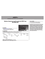
KIT FEATURES
• ISO DIN radio provision with pocket
• ISO DDIN radio provision
• Touchscreen display for climate and personalization features
• Integrated hazard button and passenger airbag light
• Radio can be mounted up top or at bottom
• Painted Matte Black
TOOLS REQUIRED
• Panel removal tool • Phillips screwdriver
• 10mm & 9/32” Socket wrench
TABLE OF CONTENTS
Dash Disassembly ..................................................2
Kit Preparation .......................................................3
Kit Assembly
–ISO DIN radio provision with pocket ..................4
–ISO DDIN radio provision .....................................4
Axxess Interface Installation ............................ 5-13
WIRING & ANTENNA CONNECTIONS
Wiring Harness: Axxess interface built into touchscreen
Antenna Adapter: Included
Ford F-150 (with 4.2” screen) 2013-2014
KIT COMPONENTS
• A) Radio/Display trim panel with touchscreen display • B) Radio/Display sub-trim panel upper (a) • C) Radio/Display sub-trim panel lower (b)
• D) Radio brackets upper (a)
• E) Radio brackets lower (b) • F) Pocket • G) (4) Panel clips • H) (11) #6 x 3/8” Phillips pan-head screws
• I) (4) #8 x 3/8” Phillips truss-head screws • J) Touchscreen display assembly and wiring harness
• K) Antenna adapter (not shown)
A B C D
H I J
E F G

1.800.221.0932
|
MetraOnline.com
2
DASH DISASSEMBLY
1. Open and lower the glove box, then
remove (3) 10mm bolts from inside the
glove box facing up. (Figure A)
2. Remove (1) 7mm screw securing the
trim panel to the right of the radio, then
unclip and set to the side. (Figure B)
3. Remove (4) 9/32” screws securing
the radio/climate control panel to the
dash, then unclip, unplug, and remove.
(Figure C)
4. Remove (4) 9/32” screws securing the
radio chassis, then unplug and remove.
(Figure D)
5. Remove (4) 9/32” screws securing
the factory display, then unplug and
remove. (Figure D)
6. Unsnap, unplug, and remove the
traction control button and save for kit
assembly.
Continue to Kit Preparation
(Figure C)(Figure A)
(Figure B)
(Figure D)

REV. 2/21/2018 INST99-5846B
3
KIT PREPARATION
1. There are two different
radio/display
sub-trim panels
to choose from. One for
mounting the radio in the upper portion
of the kit, and another one for mounting
it in the lower portion. (Figure A)
If mounting the radio in the upper
portion, a factory module will need to
be re-located:
a. Remove the module from the sub-
dash and relocate it to the bottom
of the dash opening. The mounting
brackets attached to the module will
need to be bent outward to make
room for the radio.
(Figure B) (Figure D)
(Figure A) (Figure C)
2. Attach the desired
radio/display sub-
trim panel
to the
radio/display panel
using the (12) #6 x 3/8” pan-head
screws provided. (Figure B)
3. Attach the
touchscreen display
assembly
to the
radio/display sub-panel
using the (4) #8 x 3/8” truss-head
screws provided. (Figure C)
4. Snap the factory traction control button
into the panel.
5. Attach the (4)
panel clips
provided to
the
radio/display panel
. (Figure D)
Continue to Kit Assembly

1.800.221.0932
|
MetraOnline.com
4
KIT ASSEMBLY
(Figure A) (Figure A)
ISO DIN radio provision with pocket
1. Secure the
pocket
to the
radio brackets
using the (4) #8 x 3/8” Phillips pan head
screws supplied. (Figure A)
2. Remove the metal DIN sleeve and trim
ring from the aftermarket radio.
3. Slide the radio between
radio brackets,
then secure with the screws supplied
with the radio. (Figure B)
Continue to Axxess
Interface Installation
ISO DDIN radio provision
1. Secure the radio to the
radio brackets
using the screws supplied with the radio.
(Figure B)
Continue to Axxess
Interface Installation

REV. 2/21/2018 INST99-5846B
5
AXXESS INTERFACE INSTALLATION
INTERFACE FEATURES
INTERFACE COMPONENTS
• Axxess interface (built into the touchscreen display)
• 5846 harness
• 4-pin flat to 4-pin stacked harness
• 16-pin harness with stripped leads
• 12-pin backup camera harness
• 4-pin harness with yellow RCA jacks
• Hazard harness
• Female 3.5mm connector with stripped leads
TOOLS REQUIRED
• Wire cutter • Crimp tool • Solder gun • Tape
• Connectors (example: butt-connectors, bell caps, etc.)
TABLE OF CONTENTS
Connections to be made ...........................................................................................................6-7
Installing the interface .................................................................................................................8
Initializing the interface ............................................................................................................... 9
Final assembly ..............................................................................................................................9
Extra features (SYNC)....................................................................................................................9
Touchscreen display operation ...............................................................................................10-11
Steering wheel control settings .............................................................................................12-13
• Provides accessory power (12-volt 10-amp)
• Retains R.A.P. (retained accessory power)
• Provides NAV outputs (parking brake, reverse, speed sense)
• Retains audio controls on the steering wheel
• Retains SYNC
®
• Retains the factory backup camera
• Retains balance and fade
• Micro “B” USB updatable

1.800.221.0932
|
MetraOnline.com
6
CONNECTIONS TO BE MADE
From the 5846 harness to the aftermarket radio:
• Connect the Black wire to the ground wire.
• Connect the Yellow wire to the battery wire.
• Connect the Green wire to the left rear positive speaker output.
• Connect the Green/Black wire to the left rear negative speaker output.
• Connect the Purple wire to the right rear positive speaker output.
• Connect the Purple/Black wire to the right rear negative output.
• Tape off and disregard the following (1) wire, it will not be used in this application: Blue
• For models with SYNC
®
: Connect the Red and White RCA jacks labeled “RSE/SYNC/SAT” to
the audio AUX-IN jacks of the aftermarket radio.
• For models without SYNC
®
: Connect the Red and White RCA jacks labeled
“FROM 3.5” to the audio AUX-IN jacks of the aftermarket radio.
• Disregard the DIN jack, it will not be used in this application.
Continued on the next page
From the 16-pin harness with stripped leads to the aftermarket radio:
• Connect the (2) Red wires to the accessory wire.
• If equipped with a factory subwoofer, connect the Blue/White wire to the amp turn on wire.
• If the aftermarket radio has an illumination wire, connect the Orange/White wire to it.
• If the aftermarket radio has a mute wire, and the vehicle is equipped with SYNC
®
, connect
the Brown wire to it. If the mute wire is not connected, the radio will turn off when SYNC
®
is activated.
• Connect the Gray wire to the right front positive speaker output.
• Connect the Gray/Black wire to the right front negative speaker output.
• Connect the White wire to the left front positive speaker output.
• Connect the White/Black wire to the left front negative speaker output.
• Tape off and disregard the following (4) wires, they will not be used in this application:
Green, Green/Black, Purple, Purple/Black
The following (3) wires are only for multimedia/navigation radios that require these wires.
• Connect the Blue/Pink wire to the VSS/speed sense wire.
• Connect the Green/Purple wire to the reverse wire.
• Connect the Light Green wire to the parking brake wire.

REV. 2/21/2018 INST99-5846B
7
CONNECTIONS TO BE MADE
(CONT)
12-pin backup camera harness:
There are two different methods for connecting the factory backup camera.
If retaining the camera to the aftermarket radio is desired:
• Connect the Yellow RCA jack the backup camera input of the aftermarket radio.
If retaining the camera to the touchscreen display is desired:
• Connect the Yellow RCA jack, to the Yellow RCA jack from the 4-pin harness with yellow RCA
jacks labeled “Rearview camera”.
Note:
If this method is chosen, the backup camera option must be enabled in the
Configuration Settings Screen.
4-pin harness with yellow RCA jacks:
• If retaining the factory backup camera to the touchscreen display is desired, connect the Yellow
RCA jack labeled “Rearview camera”, to the Yellow RCA jack from the 12-pin or 54-pin backup
camera harness.
• Disregard the Yellow RCA jack labeled “AUX video”, it will not be used in this application.
3.5mm jack steering wheel control retention:
• The 3.5mm jack is to be used to retain audio controls on the steering wheel control.
• For the radios listed below, connect the included
female 3.5mm connector with stripped leads,
to
the male 3.5mm SWC jack from the 5846 harness. Any remaining wires tape off and disregard:
•
Eclipse: Connect the steering wheel control wire, normally Brown, to the Brown/White wire of
the connector. Then connect the remaining steering wheel control wire, normally Brown/White,
to the Brown wire of the connector
.
•
Metra OE:
Connect the steering wheel control Key 1 wire
(Gray)
to the
Brown
wire.
•
Kenwood or select JVC with a steering wheel control wire:
Connect the
Blue/Yellow
wire to
the
Brown
wire.
Note:
If your Kenwood radio auto detects as a JVC, manually set the radio type to Kenwood.
See the instructions under changing radio type.
•
XITE:
Connect the steering wheel control SWC-2 wire from the radio to the
Brown
wire.
•
Parrot Asteroid Smart or Tablet:
Connect the 3.5mm jack into the AX-SWC-PARROT (sold separately),
and then connect the 4-pin connector from the AX-SWC-PARROT into the radio
.
Note:
The radio must be updated to rev. 2.1.4 or higher software.
•
Universal “2 or 3 wire” radio:
Connect the steering wheel control wire, referred to as Key-A or
SWC-1, to the
Brown
wire of the connector. Then connect the remaining steering wheel control wire,
referred to as Key-B or SWC-2, to the
Brown/White
wire of the connector. If the radio comes with a
third wire for ground, disregard this wire
.
Note:
After the interface has been programmed to the vehicle, refer to the manual provided with
the radio for assigning the SWC buttons. Contact the radio manufacturer for more information.
• For all other radios: Connect the 3.5mm jack into the port on the radio designated for an external
steering wheel control interface. Refer to the manual provided with the radio if in doubt as to where
the 3.5mm jack goes to.

1.800.221.0932
|
MetraOnline.com
8
INSTALLING THE INTERFACE
It is highly advisable to read the following steps beforehand, to ensure a clear understanding of
what is to be expected. The following steps must be done in the order that they are numbered.
With the vehicle completely off:
1.
Connect the
16-pin harness with stripped leads
into port “B” in the touchscreen display
.
2. Connect the 5846 harness to the wiring harnesses in the vehicle. These harnesses are
the ones removed in step 4 of dash disassembly. Then insert the 5846 harness into
port “A” in the touchscreen display. But do not install this harness until exactly before
step 1 of “Initializing the Interface”. This is a timed process.
3.
Connect the
4-pin harness with yellow RCA jacks
into port “C” in the touchscreen display.
4.
Connect the hazard harness into port “D” in the touchscreen display, then to the wiring
harness in the vehicle. This is the harness removed in step 3 of dash disassembly.
5. Disregard port “E”, it will not be used in this application.
6. Port “F” is an update port for future firmware upgrades.
A
B
C
E
F
D

REV. 2/21/2018 INST99-5846B
9
INITIALIZING THE INTERFACE FINAL ASSEMBLY
1. Secure the completed assembly into the dash using the factory hardware.
2. Snap the
radio trim panel
with
touchscreen display
over the completed assembly, and then
reassemble the dash in reverse order of disassembly.
Attention! If the interface loses power for any reason, the following steps will
need to be performed again.
1. Refer to step 2 of “Installing the interface”.
2. Press the push-to-start button to start the vehicle.
3. Program the kit:
a. Once the touchscreen display loads up, select the vehicle type; “Ford F-150 2013-2014”.
b. Wait until the radio comes on, and the touchscreen display shows
“SWC Configured*”. This process may take up to 3 minutes.
Note:
If the touchscreen display does not load up, or the radio doesn’t come on within 3
minutes, and/or the touchscreen display does not show “SWC Configured*”, turn the vehicle
off and disconnect the 5846 harnesses from port “A” in the touchscreen display. Check all
the connections, reconnect the harness into the touchscreen display, and then try again
.
* For models with steering wheel controls.
4. Test all functions of the installation for proper operation, before reassembling the dash.
SYNC:
If the vehicle is equipped with SYNC, the 99-5846B can retain this feature.
• Change the source of the radio to AUX-IN.
• Press the “Info” button on the touchscreen display to enter the SYNC menu.
Press the “HVAC” button to get back to the main menu.
EXTRA FEATURES

1.800.221.0932
|
MetraOnline.com
10
• This is the HVAC control screen which will be displayed on the touchscreen display.
This is considered the main screen.
• The upper left tab with (3) arrows will take you to the Heated/Cooled seats screen,
if applicable.
Note:
This screen will also include Heated Steering if applicable.
• The upper right tab with the gear icon will take you to the Configuration Settings screen.
• Auto climate models: The climate controls will function in the same manner that they did
with the factory climate controls.
• Manual climate models: The climate controls will function in the same manner that they
did with the factory climate controls, yet via touchscreen buttons instead. The temperature
control will display a numerical scale, with “LO” being the coldest, and “HI” being the hottest:
LO / 1-9 / HI
Note:
The “Info” button will only be shown if SYNC is to be retained.
Continued on the next page
HVAC Control screen
Manual climate controls
Automatic climate controls
TOUCHSCREEN DISPLAY OPERATION

REV. 2/21/2018 INST99-5846B
11
TOUCHSCREEN DISPLAY OPERATION
(CONT.)
• Backlight
• Four slide bars control the color of the buttons and the back-light intensity:
Red / Green / Blue / Backlight
• Backup Camera
• Enable – Enables the backup camera image to the touchscreen display
• Disable – Disables the backup camera image to the touchscreen display (default)
• Steering Wheel Controls
• Remap Buttons – For remapping the steering wheel control buttons
• Dual Assign – For dual assigning the steering wheel control buttons (long button press)
• Select Radio – For auto detecting the radio, or changing the radio type
Configuration Settings screen
• System Configuration
• Firmware version
Touchscreen calibration
• Press and hold the upper two soft buttons on either side of the touchscreen for 10 seconds.
• A screen will pop up asking for you to press the target in the screen.
• After pressing the target with your finger, the calibration process will be complete, and the
screen will disappear.

1.800.221.0932
|
MetraOnline.com
12
STEERING WHEEL CONTROL SETTINGS
Select Radio screen
* Note:
If the interface shows an Alpine radio, and you do not have an Alpine radio, that means
the interface does not detect a radio connected it, i.e., an open connection. Verify that the
3.5mm jack is connected to the correct steering wheel jack/wire in the radio.
** Note:
The AX-SWC-PARROT is required (sold separately). Also, the Parrot radio must be
updated to rev. 2.1.4 or higher through www.parrot.com.
† Note:
If you have a Clarion radio and the steering wheel controls do not work, change the
radio type to the other Clarion radio type; same for Eclipse.
‡ Note:
If you have a Kenwood radio and the touchscreen display shows a JVC radio, change
the radio type to Kenwood.
Continued on the next page
Eclipse (Type 1) †
Kenwood ‡
Clarion (Type 1) †
Sony / Dual
JVC
Pioneer/Jensen
Alpine *
Visteon
Valor
Clarion (Type 2) †
Metra OE
Eclipse (Type 2) †
LG
• To show which brand radio is “auto detected” to the interface, press the “Autodetect”
button. The radio detected will have a filled in circle. If the incorrect radio is shown, select
the proper radio.
• Following is a list of radio manufacturers that the interface presently acknowledges. Others
may be added at a later date. Universal “2 or 3 wire” radios can show up as any of these
radio manufacturers.
Parrot **
XITE
Philips
JBL

REV. 2/21/2018 INST99-5846B
13
Remap Button screen Dual Assign screen
• The interface has the ability to change the button assignment for the steering wheel
control audio buttons, except Volume-Up and Volume-Down. Follow the prompts on the
touchscreen display to remap the steering wheel control audio button(s) to your liking.
Note:
The aftermarket radio may not have all of these commands. Please refer to
the manual provided with the radio, or contact the radio manufacturer, for specific
commands recognized by that particular radio.
• The interface has the capability to assign two functions to a single button, except Volume-
Up and Volume-Down. Follow the prompts on the touchscreen display to program the
button(s) to your liking.
Note:
Seek-Up and Seek-Down come programmed as Preset-Up and Preset-Down
for a long button press.
STEERING WHEEL CONTROL SETTINGS (CONT.)

1.800.221.0932
|
MetraOnline.com
14

REV. 2/21/2018 INST99-5846B
15

KNOWLEDGE IS POWER
Enhance your installation and fabrication skills by
enrolling in the most recognized and respected
mobile electronics school in our industry.
Log onto www.installerinstitute.com or call
800-354-6782 for more information and take steps
toward a better tomorrow.
®
Metra recommends MECP
certified technicians
IMPORTANT
If you are having difficulties with the installation of this product,
please call our Tech Support line at 1-800-253-TECH. Before
doing so, look over the instructions a second time, and make
sure the installation was performed exactly as the instructions
are stated. Please have the vehicle apart and ready to perform
troubleshooting steps before calling.
Metra. The World’s Best Kits.
®
MetraOnline.com © COPYRIGHT 2018 METRA ELECTRONICS CORPORATION REV. 2/21/18 INST99-5846B
INSTALLATION INSTRUCTIONS
99-5846B
/