Page 14
induSENSOR, EDS, model S
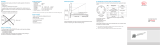
Measuring Principle4.
0
1/1
4
12
20
Output signal (mA)
Measuring range
1/2
Sensor rod
Alu tube
Sensor
housing
Measuring Principle of an eddy current long stroke dis-Fig. 1
placement sensor, alu tube is shown at the start of the measu-
ring range
Electrical Connection5.
Connector 7-pins, type Binder 712 (Model EDS-...- S ...7...) -
Installation and Assembly6.
Measuring Tube Guide and Fastening6.1
Mount the measuring tube in the piston borehold.
Dimensions for the measuring tube, see Fig. 6, see Fig. 8. When the
piston is moved in the measuring tube must not touch the sensor
shaft. Observe the measuring tube position at the zero point (= 4 mA
output), see Fig. 2. A slightly eccentric mounting of the measuring tube
has no negative influence on the sensor signal.
Mount the measuring tube in the piston by means of pressing or
glueing.
Spot clamping is not permissable.
i
The specified technical data are valid only if the
measuring tube is used supplied by MICRO-EPSILON!
Fig. 2 Zero point of the measuring tube
Measuring
range
75 100 160 200 250 300 400 500 630
Dimension a
15
(0.59)
20
(0.79)
20
(0.79)
20
(0.79)
20
(0.79)
20
(0.79)
25
(0.98)
25
(0.98)
25
(0.98)