CST rl25h Operating Instructions Manual
- Category
- Laser levels
- Type
- Operating Instructions Manual
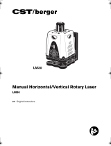
This manual is also suitable for

IMPORTANT: IMPORTANT: IMPORTANTE:
Read Before Using Lire avant usage Leer antes de usar
Operating/Safety Instructions
Consignes de fonctionnement/sécurité
Instrucciones de funcionamiento y seguridad
For English Version Version française Versión en español
See page 5 Voir page 15 Ver la página 25
Call Toll Free for
Consumer Information
& Service Locations
Pour obtenir des informations
et les adresses de nos centers
de service après-vente,
appelez ce numéro gratuit
Llame gratis para
obtener información
para el consumidor y
ubicaciones de servicio
RL25H
RL25HV
1-800-435-1859 www.cstberger.com
Page is loading ...

-3-
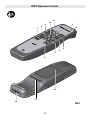
16
71
19
18
20
RL25H
RL25HV
Page is loading ...
Page is loading ...
Page is loading ...
Page is loading ...

-8-
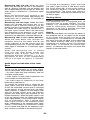
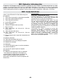
General Safety Rules
Read all instructions. Failure to follow all instructions listed below may
result in hazardous radiation exposure, electric shock, fire and/or serious
injury. The term “tool” in all of the warnings listed below refers to your mains-operated
(corded) tool or battery-operated (cordless) tool.
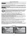
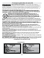
The following labels are on your laser tool for your convenience and safety. They
indicate where the laser light is emitted by the tool. ALWAYS BE AWARE of their
location when using the tool.
If glass light house breaks when dropped, contact customer service
immediately. Broken glass can cause laceration hazard and unit to
lose its IP rating.
DO NOT direct the laser beam at persons or animals and do not stare into
the laser beam yourself. This tool produces laser class 2 laser radiation
and complies with 21 CFR 1040.10 and 1040.11 except for deviations
pursuant to Laser Notice No. 50, dated June 24, 2007.
This can lead to
persons being blinded.
DO NOT remove or deface any warning or caution labels.
Removing labels increases the risk of exposure to laser radiation.
Use of controls or adjustments or performance of procedures other than those
specified in this manual, may result in hazardous radiation exposure.
ALWAYS make sure that any bystanders in the vicinity of use are made aware of
the dangers of looking directly into the laser tool.
DO NOT place the laser tool in a position that may cause anyone to stare into the
laser beam intentionally or unintentionally
. Serious eye injury could result.
ALWAYS position the laser tool securely. Damage to the laser tool and/or serious
injury to the user could result if the laser tool falls.
ALWAYS use only the accessories that are recommended by the manufacturer of
your laser tool. Use of accessories that have been designed for use with other laser
tools could result in serious injury or unsatisfactory performance.
DO NOT use this laser tool for any purpose other than those outlined in this
manual. This could result in serious injury or unsatisfactory performance.
DO NOT leave the laser tool “ON” unattended in any operating mode.
DO NOT disassemble the laser tool. There are no user serviceable parts inside. Do
not modify the product in any way. Modifying the laser tool may result in hazardous
laser radiation exposure.
!
WARNING
!
WARNING
RL25H/RL25HV

-9-
Work area safety
Keep work area clean and well lit.
Cluttered or dark areas invite accidents.
DO NOT operate the laser tool around
children or allow children to operate
the laser tool. Serious eye injury could
result.
DO NOT use measuring tools,
attachments and accessories outdoors
when lightening conditions are present.
Electrical safety
Batteries can explode or leak, cause
injury or fire. To reduce this risk,
always follow all instructions and
warnings on the battery label and
package.
Remove the batteries from the tool
when not using it for extended periods.
When storing for extended periods, the
batteries can corrode and discharge
themselves.
DO NOT short any battery terminals.
DO NOT charge alkaline batteries.
DO NOT mix old and new batteries.
SAVE THESE INSTRUCTIONS.
Replace all old batteries at the same
time with new batteries of the same
brand and type.
DO NOT mix battery chemistries.
Dispose of or recycle batteries per
local code.
DO NOT dispose of batteries in fire.
Keep batteries out of reach of children.
Personal safety
Stay alert, watch what you are doing
and use common sense when operating
a tool. Do not use a tool while you are
tired or under the influence of drugs,
alcohol or medication. A moment of
inattention while operating a tool may
result in serious personal injury or
incorrect measurement results.
Use safety equipment. Always wear
eye protection. Safety equipment such
as dust mask, non-skid safety shoes,
hard hat, or hearing protection used
for appropriate conditions will reduce
personal injuries.
DO NOT use the laser viewing
glasses as safety goggles. The laser
viewing glasses are used for improved
visualization of the laser beam, but they
do not protect against laser radiation.
DO NOT use the laser viewing
glasses as sun glasses or in traffic.
The laser viewing glasses do not afford
complete UV protection and reduce color
perception.
DO NOT use any optical tools such
as, but not limited to, telescopes or
transits to view the laser beam. Serious
eye injury could result.
DO NOT stare directly at the laser beam
or project the laser beam directly into
the eyes of others. Serious eye injury
could result.
Use caution when using measuring
tools in the vicinity of electrical
hazards.
Magnets
Keep the tool and laser target away
from cardiac pacemakers. The magnets
of the tool and laser target plate generate
a field that can impair the function of
cardiac
pacemakers.
Keep the tool and
laser target away from
magnetic data medium
and magnetically-sensitive
equipment.
The effect of the magnets of the tool and
laser target plate can lead to irreversible
data loss.
Noise Information
Do not hold the measuring tool close to
your ear! The A-weighted sound pressure
level of the audio signal at one meter
distance is 75-85dB(A). Serious injury
could result.
Use and care
Use the correct tool for your
application. The correct tool will do the
job better and safer.
Do not use the tool if the switch does
not turn it on and off. Any tool that
cannot be controlled with the switch is
dangerous and must be repaired.
Store idle tool out of the reach of
children and do not allow persons
unfamiliar with the tool or these
instructions to operate the tool. Tools
are dangerous in the hands of untrained
users.
Maintain tools. Check for misalignment
or binding of moving parts, breakage of
parts and any other condition that may
affect the operation. If damaged, repair
tool before use. Many accidents are
caused by poorly maintained tools.
Use the tool, accessories, etc., in
accordance with these instructions
and in the manner intended for the
particular type of tool, taking into

-10-
account the working conditions and the work to be performed. Use of the tool for
operations different from those intended could result in a hazardous situation.
Service
Have your tool serviced by a qualified repair person using only identical
replacement parts. This will ensure that the safety of the tool is maintained.
Develop a periodic maintenance schedule for tool.
Follow checking recalibration procedures outlined in this instruction manual.
When cleaning a tool be careful not to disassemble any portion of the tool since
internal wires may be misplaced or pinched or may be improperly mounted.
Certain cleaning agents such as gasoline, carbon tetrachloride, ammonia, etc. may
damage plastic parts.
SAVE THESE INSTRUCTIONS.
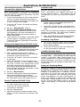
Inserting/Replacing the Battery
Always replace all batteries
at the same time. Only use
batteries from one brand and with the identical
capacity.
Remove the batteries from the tool when not
using it for extended periods. When storing for
extended periods, the batteries can corrode
and discharge themselves.
Alkaline batteries are recommended for
the tool.
When inserting, pay attention to the correct
polarity according to the representation on the
inside of the battery lid.
It is the user’s responsibility
to periodically check the
accuracy of the measuring tool as work
progresses. Always check the accuracy of
the measuring tool after it has been dropped
or subject to extreme temperatures and
temperature variations
Preparation
!
WARNING
!
WARNING

-11-
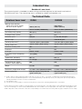
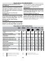
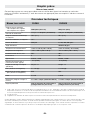
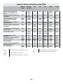
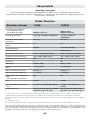
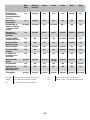
Technical Data
Rotational Laser Level RL25H RL25HV
Working range (diameter)
– without laser receiver, approx.
– with laser receiver, approx.
2000 ft (609.6 m)
200 ft (60 m)
2000 ft (609.6 m)
Leveling Accuracy
1, 2
3/32 in @ 100 ft (±0.08mm/m) 3/32 in @ 100 ft (±0.08mm/m)
Self-leveling range, typically
±8% (± 5°) ±8% (± 5°)
Leveling duration, typically
15 s 15 s
Rotational speed
600 rpm 0, 150, 300, 600 rpms
Aperture angle
10/25/50 degrees
Operating temperature
3
+14°F to +122°F (–10 to +50°C) +14°F to +122°F (–10 to +50°C)
Storage temperature
-4°F to +158°F (–20 to +70°C) -4°F to +158°F (–20 to +70°C)
Relative air humidity, max.
90% 90%
Laser class
2 3R
Laser type
635nm, <1mW 635nm, >1mW
Laser beam Ø at the exit opening,
approx.
.2 in (5mm) .2 in (5mm)
Tripod mount (horizontal)
5/8"–11 5/8"–11
Batteries (alkali-manganese)
3 x 1.5v (D) 3 x 1.5v (D)
Operating life time, approx.
–Batteries (alkali-manganese)
85h 55h
Weight
5.15 lbs 5.18 lbs
Dimensions (length xwidth xheight)
7.3 x 8.6 x 7.8 in (185x218x198mm) 7.3 x 8.6 x 7.8 in (185x218x198mm)
Degree of protection
IP56 (dust-proof and protected
against water jets)
IP56 (dust-proof and protected
against water jets)
1) at 20°C (68º F) and a temperature drift coefficient of ±1 arc sec per 1º C must be considered for any temperature deviation
above or below standard temperature. It is recommended that you periodically check your rotary laser upon receipt and peri
odically thereafter to ensure accuracy is maintained.
2) alongside the axes
3) It is the user’s responsibility to check the rotary laser accuracy if the operating temperature is exceeded.
Please observe the article number on the type plate of your measuring tool. The trade names of the individual measuring tools may
vary. The measuring tool can be clearly identified with the serial number 13 on the type plate. The rotary laser is designed to with-
stand a drop test of 1M. However it is the user’s responsibility to check the laser’saccuracy after any type of impact such as a drop.
Rotational Laser Level
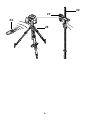
The measuring tool is intended for determining and checking precise horizontal and vertical
(RL25HV only) lines. The measuring tool is suitable for indoor and outdoor use.
Intended Use

-12-
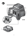
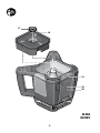
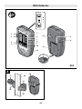
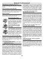
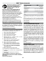
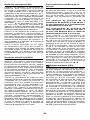
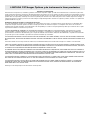
The numbering of the product features
shown refers to the illustration of the
measuring tool on the graphic page. (see
pages 3 – 6)
1. Reception lens for remote control
2. On/Off button
3. Automatic leveling indicator
4. Button for rotational operation and selection
of the rotation speed (RL25HV)
5. Button for line operation and line length
selection (RL25HV)
6. Charge-control indicator
7. ADS (Anti-Drift system) indicator
8. ADS button
9. Lower direction button
10. Upper direction button
11. Indicator for single-axis slope operation
12. Button for single-axis slope operation
13. Exit opening for laser beam
14. Variable laser beam
15. Plumb beam (RL25HV)
16. Battery compartment
17. Nut for battery compartment/battery pack
18. Tripod mount 5/8”
19. Serial number
20. Laser warning label
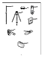
21. Laser detector*
22. Construction laser measuring rod*
23. Tripod**
24. Remote control*
25. Laser viewing glasses*
26. Wall mount/alignment unit**
27. Case*
28. Laser target plate*
* The accessories illustrated or described are
not included as standard
*Illustrated accessory may be optional on some
models and not included in standard package.
Product Features
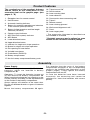
Power Supply
The measuring tool uses (3) D Alkaline
batteries, which are inserted in battery
compartment 16.
Operation: To insert the batteries loosen nut
17 and remove the battery compartment 16.
When inserting the batteries pay attention to the
correct polarity according to the representation
on the inside of the battery compartment.
Always replace all batteries at the same time.
Do not use different brands or types of batteries
together.
Mount the battery compartment 16 again.
Pay attention that the nose of the battery
compartment engages in the corresponding
recess in the housing (see illustration on the
graphic pages). Firmly tighten the battery
compartment with nut 17.
In case the batteries have been inserted
incorrectly, the measuring tool cannot be
switched on. Insert the batteries with correct
polarity.
Assembly

-13-
Operation
Initial Operation
Do not subject the measuring tool to extreme
temperatures or variations in temperature.
As an example, do not leave it in vehicles
for long time. In case of large variations in
temperature, allow the measuring tool to adjust
to the ambient temperature before putting it into
operation. In case of extreme temperatures or
variations in temperature, the accuracy of the
measuring tool can be impaired.
Avoid heavy impact to or falling down of the
measuring tool. After severe exterior effects to
the measuring tool, it is recommended to carry
out an accuracy check (see “Accuracy Check of
the Measuring Tool”, page 16) each time before
continuing to work.
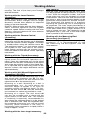
Setting Up the Measuring Tool
Position the measuring tool on a firm surface
in the horizontal or vertical position, mount it to
a tripod or to the wall mount 26 with alignment
unit. Due to the high leveling accuracy, the
measuring tool reacts sensitively to ground
vibrations and position changes. Therefore,
pay attention that the position of the measuring
tool is stable in order to avoid operational
interruptions due to re-leveling.
Switching On and Off
To switch on the measuring tool, press the On/
Off button 2. This is confirmed by brief flashing
of all indicators.
– RL25H: Immediately after switching on, the
measuring tool
laser beam 14 flashes.
– RL25HV: Immediately after switching on, the
measuring tool laser beam 14 and the plumb
beam 15 flash. Do not point the laser beam at
persons or animals and do not look into the
laser beam yourself, not even from a large
distance. The measuring tool immediately starts
automatic leveling after switching on. During
leveling, the leveling indicator 3 flashes green,
the laser flashes.
The measuring tool is leveled in as soon as
leveling indicator 3 continuously lights up green
and the laser beam is steady. The measuring
tool automatically starts in rotational operation,
the ADS function is switched on (ADS indicator
7 lights up green).
To switch off the measuring tool, press the On/
Off button 2 again.
Do not leave the switched on measuring tool
unattended and switch the measuring tool off
after use. Other persons could be blinded by the
laser beam.
When not using the measuring tool, switch it off
in order to extend the battery life.
The measuring tool is switched off automatically
to extend the battery life
–When not within the self-leveling range for
more than 30 minutes
– When the ADS function has been actuated
longer than 2 h
– When it is not switched on again within 2 h
while in hibernation mode (only possible with
remote control).
If required, reposition the measuring tool and
switch it on again.
Hibernation Mode with Storage of the
Operating Mode
With the remote control 24, the measuring
tool can be switched to hibernation mode to
conserve energy. This is confirmed by flashing
of the power LED 3.
The operating mode set on the measuring tool
is retained. When the ADS function is switched
on, the position of the measuring tool is also
monitored during hibernation mode.
To end hibernation mode, press any button on
the remote control or the keypad
Horizontal position
(RL25H/RL25HV)
Vertical position
(RL25HV)

-14-
Operation Modes
Course of X- and Y-Axis
The course of the X- and Y-axis is marked on
the housing above the rotation head.
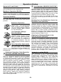
Rotational Operation (RL25H)
The measuring tool exclusively operates with
a fixed rotational speed in rotational operation,
which is also suitable for use of a laser detector.
Overview (RL25HV)
All three operating modes are possible with
the measuring tool in horizontal and vertical
position.
Rotational Operation
Rotational operation is
especially recommended
when using the laser detector.
You can select between different
rotational speeds. 600 is optimal
for use with detector.
Line Operation (Sweep/
Scanning Mode)
In this operation mode, the
variable laser beam moves
within a limited aperture angle.
This increases the visibility of
the laser beam in comparison
to rotational operation. You can
select between different aperture
angles.
Point Operation (Spot mode)
This operation mode enables
the best visibility of the variable
laser beam. As an example, it is
used for easy projecting of heights or checking
building lines.
Rotational Operation, Point Operation
(RL25HV) (600/300/150/0 RPM)
Each time after switching on, the measuring
tool is in rotational operation with the highest
rotational speed. To switch from line operation
to rotational operation, press the rotational
operation button 4. Rotational operation starts
with the highest rotational speed. To change
the rotational speed, press the rotational
operation button 4 again. The rotational speed is
decreased each time after pressing the button.
After the lowest rotational speed, the measuring
tool switches to point operation. Pressing button
4 takes you back again to rotational operation
with the highest rotational speed. When working
with the laser detector, the highest rotational
speed should be set. When working without
laser receiver, reduce the rotational speed for
improved visibility of the laser beam and use the
laser viewing glasses 25.
Line Operation (RL25HV) (10°/25°/50°)
To switch to line operation, press the line
operation button 5. The measuring tool starts
with the smallest aperture angle. To change the
aperture angle, press the line operation button
5. The aperture angle is increased in two steps;
Pressing button 5 again takes you back to line
operation with the smallest aperture angle.
Note: Due to inertia, it is possible for the laser
to slightly move beyond the end point of the
laser line.
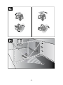
Rotating the Laser Point/Laser Line in the
Rotational Plane (RL25HV)
When automatic leveling is switched on
(indicator 11 is lit), the laser point or laser line
can be rotated by 360° in steps within the
rotational plane, no matter if the measuring tool
is in horizontal or vertical position. To rotate the
rotational plane in clockwise direction, press
button 10; to rotate counter clockwise, press
button 9. Pressing and holding the buttons
increases the speed of the rotation head in the
desired direction (See Fig. G).
Aligning the Rotational Plane in the
Vertical Position (RL25HV)
When the measuring tool is in the vertical
position, it is possible to rotate the laser point,
laser line or rotational plane around the X-axis
for easy layout or parallel alignment. For this,
press the button for single-axis slope operation
12; indicator 11 flashes. Then, press button
10 to rotate the rotational plane in clockwise
direction, and button 9 to rotate in counter
clockwise direction. Pressing and holding the
buttons increases the speed of the rotation
head in the desired direction. Rotation is
possible within a range of ±8 % (See Fig. H).
Automatic Leveling RL25H
After switching on, the measuring tool checks
the horizontal position and automatically
compensates irregularities within the self-
leveling range of approx. 8 % (±5°). When the
measuring tool is inclined by more than 8 %
after switching on or after a position change,
leveling is no longer possible. In this case, the
rotor is stopped, the laser flashes, indicators
3 and 11 flash green. In this case, switch the
measuring tool off, re-align it and switch the
measuring tool on again. Without repositioning,
the laser is automatically switched off after 30
Min.

-15-
Automatic leveling RL25H (Continued)
When the measuring tool is leveled in, it
continuously checks the horizontal position.
Automatic re-leveling takes place after position
changes. To avoid faulty measurements, the
rotor stops during the leveling process, the
laser flashes and the leveling indicator 3 flashes
green.
Because the largest difference in temperature
layers is close to the ground, the laser tool
should always be mounted on a tripod when
measuring distances exceeding 65 ft. If
possible, also set up the laser tool in the center
of the work area.
Automatic Leveling RL25HV
After switching on, the measuring tool
automatically detects the horizontal or vertical
position. To change between the horizontal and
vertical position, switch the measuring tool off,
reposition it and switch on again. After switching
on, the measuring tool checks the horizontal
and vertical position and automatically levels
out any unevenness within the self-leveling
range of approx. 8 % (±5°).
When the measuring tool is inclined by more
than 8 % after switching on or after a position
change, leveling is no longer possible. In this
case, the rotor is stopped, the laser flashes,
indicators 3, 11 flash green. In this case, switch
the measuring tool off, re-align it and switch the
measuring tool on again. Without repositioning,
the laser is automatically switched off after
30 min. When the measuring tool is leveled
in, it continuously checks the horizontal and
vertical position. Automatic re-leveling takes
place after position changes. To avoid faulty
measurements, the rotor stops during the
leveling process, the laser flashes and the
leveling indicator 3 flashes green.
Single-Axis Slope Operation
When the measuring tool is in horizontal
position, the X-axis is automatically leveled in
while in single-axis slope operation, the Y-axis
is not. With the ADS function switched on, only
the leveling of the X-axis is monitored.
Position changes of the measuring tool alongside the
Y-axis are not detected in single-axis slope operation.
To switch to single-axis slope operation, press
the button for single-axis slope operation 12.
This is confirmed by flashing (green) of the
indicator for single-axis slope operation 11.
When the ADS function is switched on, only
the X-axis is monitored; the ADS indicator is
solid green. To switch the automatic leveling on
again for both axes, press button 12 again. The
indicator for full auto-leveling operation turns
solid green. To slope the rotational plane of the
Y-axis, press the direction up 10 or down button
9. The direction of slope corresponds with the
arrow direction on buttons 10 and 9.
Anti-Drift System (ADS)
The measuring tool has an ADS function; after
position changes or shock to the measuring
tool, or in case of ground vibrations, it keeps
the measuring tool from leveling in at changed
heights, and thus prevents vertical errors.
After switching on the measuring tool, the
ADS function is switched on by default; the
ADS indicator 7 lights up green. The ADS is
activated approx. 30 s after switching on the
measuring tool or the ADS function. When the
leveling-accuracy range is exceeded after a
position change of the measuring tool or when
heavy ground vibrations are detected, the ADS
function is actuated: The rotation is stopped,
the laser flashes, the leveling indicator 3 goes
out and the ADS indicator 7 flashes red. The
current operating mode is stored. After the
ADS function has actuated, press the ADS
button 8.
The ADS function is restarted and the
measuring tool starts leveling. As soon as the
measuring tool is leveled in (leveling indicator
3 is solid green), it starts in the stored operating
mode. Now, check the height of the laser beam
with a reference point and correct the height, if
required. To switch off the ADS function, press
ADS button 8 once, or, when the ADS has
actuated (ADS indicator flashing red). Press
ADS once to switch off or to reset after ADS
has been actuated. The laser is automatically
switched off after 2 minutes and the measuring
tool after 2 hours.
Operation Modes

-16-
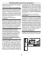
Influences on Accuracy
The ambient temperature has the greatest
influence. Especially temperature differences
occurring from the ground upward can divert
the laser beam. The deviations play a role in
excess of approx. 65-ft measuring distance and
can easily reach two to four times the deviation
at 330-ft. Because the largest difference in
temperature layers is close to the ground, the
measuring tool should always be mounted on
a tripod when measuring distances exceeding
65-ft. If possible, also set up the measuring tool
in the center of the work area.
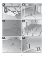
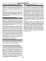
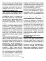
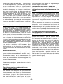
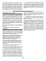
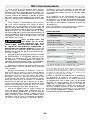
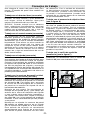
Checking the Leveling Accuracy
Apart from exterior influences, device-specific
influences (such as heavy impact or falling
down) can lead to deviations. Therefore, check
the accuracy of the measuring tool each time
before starting your work. A free measuring
distance of 50-ft on a firm surface between
two walls A and B is required for the check.
A reversal measurement must be carried out
over both axes X and Y (each positive and
negative; 4 complete measurements).
– Mount the measuring tool in the horizontal
position onto a tripod 23 (accessory) or place it
on a firm and level surface near wall A. Switch
the measuring tool on.
– After the leveling, mark the center of the laser
beam on wall A (point I).
– Rotate the measuring tool by 180°, allow it to
level in and mark the center point of the laser
beam on the apposing wall B (point II).
– Without turning the measuring tool, position
it close to wall B. Switch the measuring tool on
and allow it to level in.
– Align the height of the measuring tool (using
the tripod or by propping), so that the center
of the laser beam runs exactly against the
previously marked point II on wall B.
– Rotate the measuring tool by 180° without
changing the height. Allow it to level in and
mark the center point of the laser beam on wall
A (point III). Take care that point III is as vertical
as possible above or below point I.
– The difference d of both marked points I and
III on wall A amounts to the actual deviation of
the measuring tool for the measured axis.
Repeat the measuring procedure for the other
three axes. For this, turn the measuring tool
prior to each measuring procedure by 90°. On
the measuring section of 2 x 20m = 40 m, the
maximum allowable deviation is: 40 m x ±0.08
mm/m = ±3.2 mm. Consequently, the difference
d between points I and III for each of the four
individual measurements may not exceed
3.2 mm max. If the measuring tool should
exceed the maximum deviation in anyone of the
four measuring procedures, have it checked at
a Bosch after-sales service agent.
Accuracy Check
BA
50-ft
BA
180°
BA
A
d
B
180°

-17-
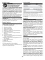
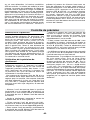
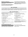
RM7 Remote Control
RM7
7
1
2
8
9
10
11
3
4
5
6
12
13
14

-18-
Remote control
Safety Notes
Read and observe all instructions.
SAVE THESE INSTRUCTIONS
FOR FUTURE REFERENCE.
Have the remote control repaired
only through a qualified repair person and only
using identical replacement parts. This will ensure
that the functionality of the remote control is
maintained. Do not operate the remote control
in explosive atmospheres, such as in the
presence of flammable liquids, gases or dusts.
Sparks can be created in the remote control
which may ignite the dust or fumes.
Read and strictly observe the safety warnings in
the operating instructions of the rotational laser.
Product Description and Specifications
Intended Use
The remote control is intended for controlling
CST/berger rotational laser levels with infra-red
receivers, in indoor and outdoor use.
Product Features
The numbering of the product features refers
to the illustration of the remote control on the
graphics page. (see page 17)
1. Hibernation mode button
2. Operation indicator
3. Sweep mode button
4. Right direction button
5. Button for “rotation in clockwise direction”
6. Lower direction button
7. Button for “rotation in counter clockwise
direction”
8. Left direction button
9. Button for rotational operation and selection
of the rotation speed
10. Button for single-axis slope operation or full
auto-leveling
11. Upper direction button
12. Battery lid
13. Latch of battery lid
14. Outlet opening for infra-red beam
The accessories illustrated or described are not
included as standard delivery.
Technical Data
Remote Control RM7
Article Number F034K69014
Working Range
1
100-ft
Operating Temperature +14ºF to 122ºF (-10ºC to +50ºC)
Storage Temperature -4ºF to 158ºF (-20ºC to +70ºC)
Batteries 2 x AA1.5v Alkaline
Weight 3.8 oz
1) The working range can be decreased by unfavourable
environmental conditions (e.g. direct sun irradiation).
Please observe the article number on the type plate of your remote
control. The trade names of individual remote controls may vary. For
clear identification of your remote control, see the serial number 13
on the type plate.
Assembly
Inserting/Replacing the Battery
Using alkaline batteries is recommended for
operation of the remote control. To open the
battery lid 12, pull on the latch 13 and remove
the battery lid. Insert the batteries. When
inserting, pay attention to the correct polarity
according to the representation on the inside of
the battery compartment.
The batteries must be replaced when operation
indicator 2 no longer lights up after pressing any
button on the remote control.
Always replace all batteries at the same time.
Only use batteries from one brand and with the
identical capacity.
Remove the batteries from the remote control
when not using it for longer periods. When
storing for longer periods, the batteries can
corrode and discharge themselves.
Operation
Initial Operation
Protect the remote control against moisture and
direct sunlight.
Do not subject the remote control to extreme
temperatures or variations in temperature.
As an example, do not leave it in vehicles for
longer periods. In case of large variations in
temperature, allow the remote control to adjust
to the ambient temperature before putting it into
operation.
The remote control remains ready for operation
as long as batteries with sufficient voltage are
inserted.
Set up the rotational laser in such a manner that
the signals of the remote control directly reach
one of the receiption lenses on
the rotational laser (for this, see the operating
instructions of the rotational laser). When
the remote control cannot be pointed directly
against a receiption lens, the working range is
reduced. By reflecting the signal (e.g. against
walls), the working range can be improved,
even for indirect signals. After pressing a button

-19-
on the remote control, the illuminated operation
indicator 2 indicates that a signal was sent out.
Switching the rotational laser on/off with the
remote control is not possible.
Operating Modes
Function of buttons that are both on the
rotational laser level as well as on the remote
control do not differ. With exception of the
hibernation mode, no additional functions of the
rotational laser level can be controlled with the
remote control. Example: Pressing the rotation
operation button switches the rotational laser
level from line operation to rotation operation.
This happens no matter if you press the rotation
operation button on the rotational laser level
or on the remote control. When the rotational
laser level does not have different rotational
speeds, then the rotational speed can also not
be changed with the remote control.
The ADS function cannot be controlled with
the remote control. For detailed information of
the rotational laser functions, see the operating
instructions of the rotational laser.
Hibernation Mode
The rotational laser level can be switched to
hibernation mode for 2 hours (max.). For this,
press the hibernation mode button 1 on the
remote control. Rotation laser level is switched
off, and the set operating mode is saved.
hibernation mode can only be started with the
remote control.
Press any button on the remote control to restart
the rotational laser level in the saved operating
mode.
Rotation, Line and Point Operation
By pressing the rotation operation button 9,
you can switch from line to rotation operation
or decrease the rotational speed in steps down
to zero (point operation). By pressing the line
operation button 3, you can switch from rotation
to line operation or increase the aperture angle
in steps.
Rotating the Laser Point/Laser Line in the
Rotational Plane
The laser point or the laser line can be rotated in
steps by 360° within the rotational plane. Press
button 5 to rotate in clockwise direction, and
button 7 to rotate in counter clockwise direction
(See Fig. G).
Pressing and holding the buttons increases
the speed of the rotation head in the desired
direction.
Rotating is (independent of the
position of the rotational laser level) also
possible in single-axis slope operation (See Fig.
G).
Single-axis Slope Operation/Aligning the
Rotational Plane in the Vertical Position
Depending on the position of the rotational
laser level, you can rotate the rotational plane
around the X or Y-axis by pressing upper
direction button 11, lower direction button 6,
right direction button 4 and left direction button
8. For this, press the button for single-axis
slope operation 10 first. When the rotational
laser level is in the horizontal position, you can
rotate the rotational plane around the Y-axis
with the upper direction button 11 and lower
direction button 6. When the rotational laser
level is in the vertical position, you can rotate
the rotational plane around the X-axis with right
direction button 4 and left direction button 8
(See Fig. G).
Maintenance and Service
Maintenance and Cleaning
Keep the remote control clean at all times.
Do not immerse the remote control into water or
other fluids.
Wipe off debris using a moist and soft cloth. Do
not use any cleaning agents or solvents.
If the remote control should fail despite the care
taken in manufacture and testing, repair should
be carried out by an authorised customer
services agent for Bosch power tools. Do not
open the remote control yourself.

-20-
8
9
10
2
1
3
6
14
11
7
5
4
13
12
B
A
C
17
16
19
18
20
21
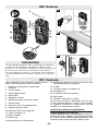
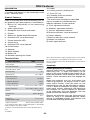
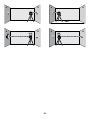
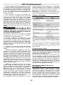
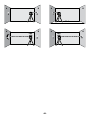
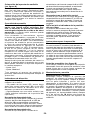
RD1 Detector
The numbering of the product features shown
refers to the illustration of the tool above.
1. Button for adjustment of measuring
accuracy
2. On/Off switch
3. Audio signal button
4. Back LEDs
5. Magnetic mounts
6. Reception area for the laser beam
7. Center mark
8. Direction LED “move downward”
9. Center-indication LED
10. Direction LED “move upward”
11. Latch of battery lid
12. Serial number
13. Battery lid
14. Mounting hole for M6 thread
15. Mounting Bracket (actual bracket may
be different from the diagram)
16. Holder
17. Locking screw for leveling rod
18. Leveling rod*
19. Fastening screw for bracket
20. Spirit level
21. Retainer openings for holder
Accessories shown or described are not part
of the standard delivery scope of the product.
A complete overview of accessories can be
found in our accessories program.
Installing and Removing Batteries
Inserting/Replacing the Battery
Alkaline batteries are recommended for the tool.
Pull the latch 11 of battery lid outward and open
the battery lid 13. When inserting batteries, pay
attention to the correct polarity. When in the
The CST/berger Detector aids in locating and targeting
a visible or invisible beam emitted by a Rotary laser;
perfect for use in outdoor conditions, where sunlight and
distance may make locating the beam more difficult.
The laser detector includes a rod clamp which allows to
mount the detector onto square, round or oval sighting
rods.
Introduction
RD1 Features

-21-
case of a dead battery, the tool will beep and
flash the LEDs then automatically shut down
when battery has been exhausted.
Remove the batteries from the tool when not
using it for extended periods. When storing for
extended periods, the batteries can corrode and
discharge themselves. To replace batteries,
detach the rod clamp (fig. C) from the detector
by turning the knob 19 on the rod clamp. Open
the battery door 11 by pulling latch.
Install batteries with correct polarity. Close the
battery door and engage the latch.
– To attach the rod clamp (fig. C) to the
detector, align projections on the rod clamp
with corresponding recess on the back of the
detector, and tighten the knob 19. To detach
rod clamp from the detector, unscrew the knob
19 completely.
– To attach the rod clamp to leveling rod 18,
loosen the knob 17 on the rod clamp, slide the
rod clamp on the leveling rod 18 to the desired
location, and tighten the knob 17. The spirit
level 20 can be used to approximately level the
leveling rod. Adjust position of leveling rod until
bubble in spirit level 20 is within the circle.
Wear eye protection. If
Spirit Level leaks, soak
up with appropriate absorbent material
and dispose of safely. Spirit Level contains
flammable liquid that may cause respiratory
tract, eye and skin irritation.
– Turn on the instrument by pressing the ON/
OFF button on the keypad. The LCD symbols
will momentarily be lit and the unit will beep
once. The Coarse bandwidth indicator and soft
volume indicator will remain lit.
– Expose the beam capture window of the
laser detector towards the direction of the laser.
– Slowly move the laser detector in an upward
and downward direction until the LCD beam
indicator arrows appear and/or a pulsing audio
signal is heard. Use the Bandwidth Resolution
Selection feature to choose between the Fine/
Coarse setting. Coarse resolution setting is
for approximating level or for initial locating of
the center level point. Fine resolution setting is
used for most accurate pin pointing of level.
– Move the detector upward when the bottom
arrow icon is lit (fig. 5) (with volume on, a slow
pulsing audio tone is heard). Move the detector
downward when the top arrow icon is lit (fig. 3)
(with volume on, a rapid pulsing audio tone is
heard). When the line is level, the level laser
line indicator will be lit (fig. 4) (with volume on, a
solid audio tone will be heard).
If the detector is not struck by a laser beam
after 4-6 minutes, the detector will automatically
shut itself off to preserve battery life. Turn the
instrument back on using the power button.
Note: The detector will only work when the
instrument is in pulse mode.
Technical data
Laser Detector RD1
Working Range
1
Typ. Upto 500-ft (150 m)
Measuring Accuracy:
“Fine “ Adjustment
“Medium” Adjustment
±1.5 mm
±3 mm
Operating Temperature 32ºF to 122ºF (0ºC to + 50ºC)
Storage Temperature -4ºF to 158ºF (-20ºC to + 70ºC)
Battery 1 x 9v 6LR61
Battery Life Typ. 30 Hours
Weight 0.75lb (0.34 Kg)
Dimensions 5” x 2.25” x 1”
(131 x 57 x 29 mm)
1) The working range can be decreased by unfavorable environmental
conditions (e.g. direct sun irradiation).
Please observe the article number on the type plate of your tool. The
trade names of the individual tools may vary. The tool can be clearly
identified with the serial number 12 on the type plate.
Initial Operation
Protect the tool against moisture. Do not
subject the tool to extreme temperatures or
variations in temperature. As an example, do
not leave it in vehicles for longer periods. In
case of large variations in temperature, allow
the tool to adjust to the ambient temperature
before putting it into operation. In case
of extreme temperatures or variations in
temperature, the accuracy of the tool can be
impaired.
Setting Up the Tool (see figure A)
Position the tool at least 3ft (1m) away from
the rotary laser. Switch on the rotary laser, and
select horizontal or vertical operation. Position
the tool in such a manner that the laser beam
can reach the reception area 6. Align the tool
in such a manner that the laser beam runs
laterally through the reception area (as shown
in the figure).
Switching On and Off
A loud audio signal sounds when
switching on the tool. Therefore, keep the
tool away from your ear or other person
when switching on.
The loud audio signal
can cause hearing defects.
!
WARNING
RD1 Operation

-22-
RD1 Operation
To switch on the tool, press the On/Off button
2. All LEDs light up briefly and an audio signal
sounds. To switch off the tool, press the On/Off
button 2 again. Before switching off, all LEDs
briefly light up. When no button is pressed on
the tool for approx. 6 minutes and when no
laser beam reaches the reception area 6 for 6
minutes, the tool automatically switches off in
order to save the battery. The switching off is
indicated by brief lighting up of all LEDs.
Selecting the Setting of the Center
Indicator
With button 1, you can specify with which
accuracy the position of the laser beam is
indicated as central on the reception area:
– “Fine” adjustment
– “Medium” adjustment
Whenever switching on the tool, the accuracy
level “Fine” is set.
Direction Indicators
The position of the laser beam on the reception
area 6 is indicated:
– via the LEDs “move downward” 8, “move
upward” 10 or the center-indication LED 9 on
the front and back side of the tool.
– optionally via the audio signal (see “Audio
Signal for Indication of the Laser Beam”).
Tool too low:
When the laser beam runs through the top
half of the reception area 6, the corresponding
direction LED 10 light up. When the audio signal
is switched on, a slowbeat signal sounds. Move
the tool upward in the direction of the center
line.
Tool too high:
When the laser beam runs through the bottom
half of the reception area 6, the corresponding
direction LED 8 light up. When the audio signal
is switched on, a fastbeat signal sounds. Move
the tool downward in the direction of the center
line.
Tool in center position:
When the laser beam runs through the
reception area 6 at the center mark 7, the
corresponding centerindication LED 9 light
up. When the audio signal is switched on, a
continuous signal sounds.
Audio Signal for Indication of the Laser
Beam
The position of the laser beam on the reception
area 6 can be indicated via an audio signal.
After the tool has been switched on, the volume
level can be switched off. To switch off the
audio signal, push the audio signal button 3.
Working Advice
Marking
When the laser beam runs through the
center of the reception area 6, its height can
be marked at the center mark 7 right and left
on the tool. When marking, take care to align
the tool exactly vertical (for horizontal laser
beam), or horizontal (for vertical laser beam),
as otherwise the marks are offset with respect
to the laser beam.
Attaching with the Magnet (see figure B)
When a mounting bracket is not required, the
tool can be attached to steel parts via the top
side using the magnet mounts 5.

-23-
RD5
4
14
13
3
2
1
10
11
7
6
5
8
9
8
4
12
17
16
19
18
20
15
A
bac
f
d
e
gh
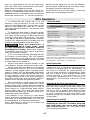
RD5 Detector

-24-
RD5 Features
Intended Use
The measuring tool is intended for swift finding
of rotating laser beams in the wavelength listed
in the “Technical Data”.
Product Features
The numbering of the product features shown
refers to the illustration of the measuring tool on
the graphic page. (See page 23) Laser Detector
1. Button for adjustment of the measuring
accuracy
2. Audio signal button
3. Reception area for the laser beam
4. Display
5. Sensor for Strobe ShieldTM function
6. Direction LED “move downward”
7. Center-indication LED
8. Center mark
9. Direction LED “move upward”
10. On/Off button
11. Speaker
12. Serial number
13. Battery lid
14. Retainer openings for holder
15. Holder
16. Locking screw for leveling rod
17. “Cut & fill” rod*
18. Fastening screw for bracket
19. Spirit level holder
*The accessories illustrated or described
are not included as standard delivery.
Indicator elements of laser receiver
a) “Fine” adjustment indicator
b) “Medium” adjustment indicator
c) “Coarse” adjustment indicator
d) Direction indicator “move downward”
e) Center indicator
f) Direction indicator “move upward”
g) Battery low indicator
h) Audio signal indicator
Technical Data
Laser Detector RD5
Article Number F034K9012
Receivable wavelength 635–650 nm
Receivable rotation speed
2
>150RPM
Receiving angle 45°
Working Range
1
Up to 1400-ft
Measuring accuracy
3
– “Fine adjustment”
– “Medium adjustment”
– “Coarse adjustment”
±0.75mm
±1.5mm
±3mm
Operating Temperature +14ºF to 122ºF (-10ºC to +50ºC)
Storage Temperature -4ºF to 158ºF (-20ºC to +70ºC)
Batteries 2 x 1.5 V LR06 (AA)
Operating Time Approx. 30 Hours
Weight 9 oz.
Dimensions
(Length x width x height
3.1 x 1.2 x 6"
Degree of Protection IP57 Dust Proof & Water Tight
1) The working range (radius) can be reduced due to unfavourable
ambient conditions (e.g. direct sunlight).
2) depends on clearance between laser receiver and rotational laser
level.
3) @ 100 m.
Please observe the article number on the type plate of your measuring
tool. The trade names of the individual measuring tools may vary.
The measuring tool can be clearly identified with the serial number 14
on the type plate.
Assembly
Inserting/Replacing the Battery
Alkaline batteries are recommended for the
measuring tool. To open the battery lid 13,
press on the latch 12 and fold the battery lid up.
Insert the batteries. Install batteries with correct
polarity. Close the battery door and engage the
latch.
When the batteries are low, the battery low
indicator g appears on display 4 and a short
audio signal sounds. From this point on, the
measuring tool can still be operated for approx.
2 to 4 h. When the batteries are empty, another
audio signal sounds; afterwards, the measuring
tool switches off. Always replace all batteries
at the same time. Only use batteries from one
brand and with the identical capacity.
Remove the batteries from the measuring tool
when not using it for extended periods. When
storing for extended periods, the batteries can
corrode and discharge themselves.

-25-
RD5 Operation
– To attach the rod clamp (fig. A) to the
detector, align projections on the rod clamp
with corresponding recess on the back of the
detector, and tighten the knob 19. To detach rod
clamp from the detector, unscrew the knob 19
completely.
– To attach the rod clamp to leveling rod 18
loosen the knob 17 on the rod clamp, slide the
rod clamp on the leveling rod 18 to the desired
location, and tighten the knob 17. Spirit level 20
can be used to approximately level the leveling
rod. Adjust position of leveling rod until bubble
in spirit level 20 is within the circle.
Wear eye protection. If
Spirit Level leaks, soak
up with appropriate absorbent material
and dispose of safely. Spirit Level contains
flammable liquid that may cause respiratory
tract, eye and skin irritation.
– Turn on the instrument by pressing the ON/
OFF button on the keypad. The LCD symbols
will momentarily be lit and the unit will beep
once. The Coarse bandwidth indicator and soft
volume indicator will remain lit.
– Expose the beam capture window of the
laser detector towards the direction of the laser.
– Slowly move the laser detector in an upward
and downward direction until the LCD beam
indicator arrows appear and/or a pulsing audio
signal is heard. Use the Bandwidth Resolution
Selection feature to choose between the Fine/
Coarse setting. Coarse resolution setting is
for approximating level or for initial locating of
the center level point. Fine resolution setting is
used for most accurate pin pointing of level.
Initial Operation
Do not subject the measuring tool to extreme
temperatures or variations in temperature.
As an example, do not leave it in vehicles
for long time. In case of large variations in
temperature, allow the measuring tool to adjust
to the ambient temperature before putting it
into operation. In case of extreme temperatures
or variations in temperature, the accuracy of
the measuring tool can be impaired. Position
the laser detector at least 2-ft away from the
rotational laser level. Position the laser detector
in such a manner that the laser beam can reach
the reception area 3.
If the rotational laser has several rotational
speeds, set to the highest speed possible.
Switching On and Off
A loud audio signal
sounds when switching
on or operating the measuring tool.
“At a distance of 0.2 m, the A-weighted
sound pressure level of the audio signal
can be up to 95 dB(A).” Do not hold the
measuring tool close to your ear! The loud
audio signal can cause hearing damage.
To switch on the measuring tool, press the On/
Off button 10. An audio signal sounds and all
display indicators light up briefly.
To switch off the measuring tool, press the On/
Off button 10 again. This is confirmed by a
double beep.
When no laser beam reaches the reception
area for approx. 6 minutes, the measuring tool
automatically switches off to save the batteries.
The switching off is indicated by an audio
signal. When not using the measuring tool,
switch it off in order to extend the battery life.
Selecting the Setting of the Center
Indicator
With button 1, you can specify the accuracy
with which the position of the laser beam is
indicated as centerd on the reception area:
– “Fine” adjustment, (indication a on the display)
– “Medium” adjustment, (indication b on the
display)
– “Coarse” adjustment, (indication c on the
display).
When changing the accuracy setting, a single,
two or three beeps sound, depending on the
selected setting. The accuracy setting is stored
when switching off the measuring tool.
Direction Indicators
The position of the laser beam on the reception
area 3 is indicated:
– via the direction indicators “move downward”
d, “move upward” for the center indicator e on
the display 4 on the front and back side of the
measuring tool,
– via the LEDs “move downward” 6, “move
upward” 9 or the center-indication LED 7 on the
front side of the measuring tool,
– optionally via the audio signal (see “Audio
Signal for Indication of the Laser Beam”, page
9).
!
WARNING
!
WARNING
Page is loading ...
Page is loading ...
Page is loading ...
Page is loading ...
Page is loading ...
Page is loading ...
Page is loading ...
Page is loading ...
Page is loading ...
Page is loading ...
Page is loading ...
Page is loading ...
Page is loading ...
Page is loading ...
Page is loading ...
Page is loading ...
Page is loading ...
Page is loading ...
Page is loading ...
Page is loading ...
Page is loading ...
Page is loading ...
Page is loading ...
Page is loading ...
Page is loading ...
Page is loading ...
Page is loading ...
Page is loading ...
Page is loading ...
Page is loading ...
Page is loading ...
Page is loading ...
Page is loading ...
Page is loading ...
Page is loading ...
Page is loading ...
Page is loading ...
Page is loading ...
Page is loading ...
Page is loading ...
Page is loading ...
Page is loading ...
Page is loading ...
Page is loading ...
Page is loading ...
Page is loading ...
Page is loading ...
Page is loading ...
Page is loading ...
Page is loading ...
Page is loading ...
Page is loading ...
Page is loading ...
Page is loading ...
Page is loading ...
-
 1
1
-
 2
2
-
 3
3
-
 4
4
-
 5
5
-
 6
6
-
 7
7
-
 8
8
-
 9
9
-
 10
10
-
 11
11
-
 12
12
-
 13
13
-
 14
14
-
 15
15
-
 16
16
-
 17
17
-
 18
18
-
 19
19
-
 20
20
-
 21
21
-
 22
22
-
 23
23
-
 24
24
-
 25
25
-
 26
26
-
 27
27
-
 28
28
-
 29
29
-
 30
30
-
 31
31
-
 32
32
-
 33
33
-
 34
34
-
 35
35
-
 36
36
-
 37
37
-
 38
38
-
 39
39
-
 40
40
-
 41
41
-
 42
42
-
 43
43
-
 44
44
-
 45
45
-
 46
46
-
 47
47
-
 48
48
-
 49
49
-
 50
50
-
 51
51
-
 52
52
-
 53
53
-
 54
54
-
 55
55
-
 56
56
-
 57
57
-
 58
58
-
 59
59
-
 60
60
-
 61
61
-
 62
62
-
 63
63
-
 64
64
-
 65
65
-
 66
66
-
 67
67
-
 68
68
-
 69
69
-
 70
70
-
 71
71
-
 72
72
-
 73
73
-
 74
74
-
 75
75
-
 76
76
-
 77
77
-
 78
78
-
 79
79
-
 80
80


CST rl25h Operating Instructions Manual
- Category
- Laser levels
- Type
- Operating Instructions Manual
- This manual is also suitable for
Ask a question and I''ll find the answer in the document
Finding information in a document is now easier with AI
Other documents
-
Cateye HL-EL520 User manual
-
Bosch GTL2 GLL2 User manual
-
Bosch GRL 500 HCK User guide
-
Bosch GLL 3-15 User manual
-
-
-
-
-
Ryobi LSL-100 Owner's Operating Manual
-
Bosch Power Tools GPL 3 Professional User manual