Bosch GLL 3-15 User manual

Category
Laser levels
Type
User manual
IMPORTANT: IMPORTANT : IMPORTANTE:
Read Before Using Lire avant usage Leer antes de usar
Operating/Safety Instructions
Consignes de fonctionnement/sécurité
Instrucciones de funcionamiento y seguridad
For English Version Version française Versión en español
See page 6 Voir page 13 Ver la página 21
1-877-BOSCH99 (1-877-267-2499) www.boschtools.com
Call Toll Free for
Consumer Information
& Service Locations
Pour obtenir des informations
et les adresses de nos centres
de service après-vente, appelez
ce numéro gratuit
Llame gratis para
obtener información
para el consumidor y
ubicaciones de servicio
GLL 3-15
-6-
Read all instructions.
Failure to follow all
instructions listed below may result in
hazardous radiation exposure, electric
shock, fire and/or serious injury.
SAVE ALL WARNINGS AND
INSTRUCTIONS FOR FUTURE
REFERENCE
The term “tool” in the warnings listed below
refers to your mains-operated (corded) tool or
battery-operated (cordless) tool.
The following labels are on your laser tool
for your convenience and safety. They
indicate where the laser light is emitted
by the tool. ALWAYS BE AWARE of their
location when using the tool.
Do not direct the laser beam
at persons or animals and do
not stare into the laser beam
yourself. This tool produces
laser class 2 laser radiation and
complies with 21 CFR 1040.10 and 1040.11
except for deviations pursuant to Laser
Notice No. 50, dated June 24, 2007. This can
lead to persons being blinded.
Changes or modifications to this equipment
not expressly approved by the party
responsible for compliance could void the
user’s authority to operate the equipment.
Use of controls or adjustments or
performance of procedures other than those
specified herein may result in hazardous
radiation exposure.
DO NOT remove or deface any warning or
caution labels. Removing labels increases the
risk of exposure to laser radiation.
ALWAYS make sure that any bystanders
in the vicinity of use are made aware of the
dangers of looking directly into the laser
tool.
DO NOT place the laser tool in a position
that may cause anyone to stare into the
laser beam intentionally or unintentionally.
Serious eye injury could result.
ALWAYS position the laser tool securely.
Damage to the laser tool and/or serious injury to
the user could result if the laser tool fails.
ALWAYS use only the accessories that are
recommended by the manufacturer of your
laser tool. Use of accessories that have been
designed for use with other laser tools could
result in serious injury.
DO NOT use this laser tool for any purpose
other than those outlined in this manual.
This could result in serious injury.
DO NOT leave the laser tool “ON”
unattended in any operating mode.
DO NOT disassemble the laser tool. There
are no user serviceable parts inside.
DO NOT modify the product in any way.
Modifying the laser tool may result in hazardous
laser radiation exposure.
DO NOT use the laser viewing glasses as
safety goggles. The laser viewing glasses
are used for improved visualization of the laser
beam, but they do not protect against laser
radiation.
DO NOT use the laser viewing glasses as
sun glasses or in traffic. The laser viewing
glasses do not afford complete UV protection
and reduce color perception.
DO NOT use any optical tools such as, but
not limited to, telescopes or transits to view
the laser beam. Serious eye injury could result.
DO NOT stare directly at the laser beam or
project the laser beam directly into the eyes
of others. Serious eye injury could result.
Work area safety
Keep work area clean and well lit. Cluttered
or dark areas invite accidents.
DO NOT operate the laser tool around
children or allow children to operate the
laser tool. Serious eye injury could result.
General Safety Rules
!
WARNING
-7-
Electrical safety
Batteries can explode or leak, cause injury
or fire. To reduce this risk, always follow all
instructions and warnings on the battery label
and package.
DO NOT short any battery terminals.
DO NOT charge alkaline batteries.
DO NOT mix old and new batteries.
Replace all of them at the same time with
new batteries of the same brand and type.
DO NOT mix battery chemistries. Dispose
of or recycle batteries per local code.
DO NOT dispose of batteries in fire.
Keep batteries out of reach of children.
Remove batteries if the device will not be
used for several months.
Personal safety
Stay alert, watch what you are doing and
use common sense when operating a tool.
Do not use a tool while you are tired or
under the influence of drugs, alcohol or
medication. A moment of inattention while
operating a tool may result in serious personal
injury or incorrect measurement results.
Use safety equipment. Always wear eye
protection. Safety equipment such as dust
mask, non-skid safety shoes, hard hat, or
hearing protection used for appropriate
conditions will reduce personal injuries.
Mounting Magnets
Keep the tools mounting
magnets away from cardiac
pacemakers. The magnets 14
generate a field that can impair
their function.
Keep the tools mounting magnets
away from magnetic data medium and
magnetically-sensitive equipment. The effect
of the magnets 14 can lead to irreversible data
loss.
Use and care
Use the correct tool for your application.
The correct tool will do the job better and safer.
Do not use the tool if the switch does not
turn it on and off. Any tool that cannot be
controlled with the switch is dangerous and
must be repaired.
Store idle tool out of the reach of children
and do not allow persons unfamiliar with
the tool or these instructions to operate
the tool. Tools are dangerous in the hands of
untrained users.
Maintain tools. Check for misalignment or
binding of moving parts, breakage of parts
and any other condition that may affect the
operation. If damaged, tool repaired before
use. Many accidents are caused by poorly
maintained tools.
Use the tool, accessories, etc., in
accordance with these instructions and in
the manner intended for the particular type
of tool, taking into account the working
conditions and the work to be performed.
Use of the tool for operations different from
those intended could result in a hazardous
situation.
Service
Have your tool serviced by a qualified repair
person using only identical replacement
parts. This will ensure that the safety of the tool
is maintained.
Develop a periodic maintenance schedule
for tool. When cleaning a tool be careful not
to disassemble any portion of the tool since
internal wires may be misplaced or pinched
or may be improperly mounted. Certain
cleaning agents such as gasoline, carbon
tetrachloride, ammonia, etc. may damage
plastic parts.
SAVE THESE INSTRUCTIONS.
-8-
The numbering of the product features shown
refers to the illustration of the tool on the graphic
page.
1 Exit opening for laser beam
2 Automatic leveling indicator
3 On/Off button / Operating mode button
4 Switch for automatic leveling/ locking the
leveling unit
5 Tripod mount 1/4-20
6 Latch of battery lid
7 Battery lid
8 Laser warning label
9 Positioning device*
10 Mounting screw for positioning device
11 Swiveling disc to move laser left to right
12 Fine adjustment knob
13 Ceiling grid clip
14 Magnets
15 Retractable feet
16 Screw hole for positioning device
17 Laser viewing glasses*
18 Tripod*
19 Laser target measuring plate
20 Protective carrying pouch
*The accessories illustrated or described are
not included as standard delivery.
Features
Article number . . . . . . . . . . . . 3 601 K73 C10
Working range, min.
1)
. . . . . . . . . . . .50 ft (15 m)
Leveling Accuracy: . . . . . up to ± 3/16 in @ 30 ft
(± 0.5 mm/m)
Self-leveling range, typically . . . . . . . . . . . . ±4°
Leveling duration, typically . . . . . . . . . . . . . . .6 s
Operating temperature . . . . . . . .30° F to 104° F
(–1° C to +40° C)
Storage temperature . . . . . . . . .14° F to 158° F
(–10° C to +70° C)
Relative air humidity, max . . . . . . . . . . . . . 90 %
Laser class . . . . . . . . . . . . . . . . . . . . . . . . . . . . 2
Laser type . . . . . . . . . . . . . . . . . 635 nm, <1mW
Mount threading . . . . . . . . . . . . . . . . . . . 1/4”-20
Batteries . . . . . . . . . . . . . . . . . . . . . 4 x AA 1.5V
Operating lifetime, approx. . . . . . . . . . . . . . .15 h
Weight . . . . . . . . . . . . . . . . . . . . . . . 1 lb (0.5 kg)
Dimensions . . . . . . . . . . . . . . . .3.8” x 2.6” x 4.7”
(97 x 65 x 120 mm)
The tool can be clearly identified with the serial
number 8 on the type plate.
Technical Data
Preparation
Inserting/Replacing the Battery
Use only alkaline batteries.
To open the battery lid 7, push the latch of the
battery lid 6 and turn the battery lid up. Insert
the supplied batteries.
When inserting, pay attention to the correct
polarity according to the representation on the
inside of the battery compartment.
Always replace all batteries at the same time.
Only use batteries from one brand and with the
identical capacity.
!
WARNING
Remove the batteries from
the tool when not using it
for extended periods. When storing for
extended periods, the batteries can corrode and
discharge themselves.
The tool is intended for determining and checking horizontal and vertical level, transfer plumb
points, and squaring. The measuring tool is suitable exclusively for operation in enclosed working
sites.
Intended Use
1)
The working range can be decrease by unfavorable environmental conditions (e.g. direct sun irradiation)
-9-
Initial Operation
Protect the tool against
moisture and direct sun
irradiation.
Do not subject the tool to extreme
temperatures or variations in
temperature. As an example, do not leave
it in vehicles for longer periods. In case of
large variations in temperature, allow the tool
to adjust to the ambient temperature before
putting it into operation. In case of extreme
temperatures or variations in temperature, the
accuracy of the tool can be impaired.
Avoid heavy impact or falling of the tool.
After heavy exterior impact on the tool, an
accuracy check should always be carried
out before continuing to work (see “Leveling
Accuracy”).
Switch the tool off during transport. Push
the switch for automatic leveling 2 to the
position when transporting the measuring
tool. This locks the leveling unit, which can be
damaged in case of intense movement.
Switching On and Off
To switch on the tool, press the On/Off button 3.
Immediately after switching on, the tool sends
laser beams out of the exit openings 1.
Do not point the laser beam at persons or
animals and do not look into the laser beam
yourself, not even from a large distance.
This can lead to persons or animals being
blind.
To switch off the tool, press the On/Off button
3 until the automatic leveling indicator 2 goes
out. Push the switch for automatic leveling 4 to
the
position.
Do not leave the switched on measuring
tool unattended and switch the tool off
after use. Other persons could be blinded by
the laser beam.
When not using the tool, switch it off in order to
extend battery life.
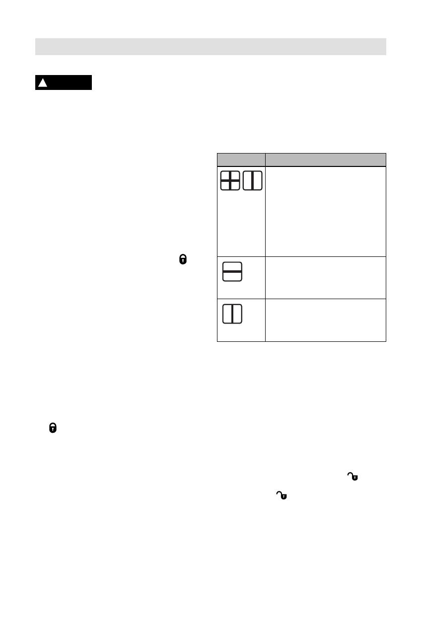
Operating Modes
The tool has total of three operation modes that
can be switched through in sequence:
Cross-line operation: Produces a horizontal
and vertical laser line in the front and a
vertical laser line at a 90° angle on the side.
Horizontal operation: Produces a horizontal
laser line in the front.
Vertical operation: Produces a vertical laser
line in the front.
After switching on, the tool is in cross-line
operating mode with self-leveling. To change
the operating mode, press the On/Off button/
operating mode button 3 as often as required
until the requested operating mode is set.
All operating modes can be selected both with
and without automatic leveling.
Symbol Operating Mode
Cross-line operation (see
figures A-C): The measuring tool
generates a horizontal and a
vertical laser line out of the front
laser beam exit opening as well
as a vertical laser line out of laser
beam exit opening 1 on the side.
Both vertical laser lines project at
a 90° angle to each other.
Horizontal operation (see figure
D): The measuring tool generates
a horizontal laser line out of the
front laser beam exit opening 1.
Vertical operation (see figure E):
The measuring tool generates a
vertical laser line out of the front
laser beam exit opening 1.
Application
The measuring tool is used for determining and
checking horizontal and vertical level as well as
for indicating slopes. With the two vertical lines
that run a 90° angle, squaring (3-4-5) can be
marked and checked.
Automatic Leveling
Working with Automatic Leveling
Position the tool on a level and firm surface,
mount, or a tripod 10.
For work with automatic leveling, slide the
switch for automatic leveling 4 to the
position. The automatic leveling indicator 2
lights up green (
symbol/ “green” ).
If the automatic leveling function is not
possible, e.g. because the surface on which the
measuring tool stands deviates by more than
±4° from the horizontal plane, the laser beams
flash. The leveling indicator 2 lights up red and
an audio signal sounds.
Do not hold the measuring tool close to
your ear! The loud audio signal can cause
hearing defects.
Operation
!
WARNING
-10-
In this case, bring the tool to the level position
and wait for the self-leveling to take place. As
soon as the tool is within the self-leveling range
of ±4°, the laser lines light up continuously.
The leveling indicator 2 lights up green and the
audio signal turns off.
When not within the self-leveling range of ±4°,
working with automatic leveling is not possible,
because it cannot be assured that the laser
lines run at a right angle to each other or are
level.
In case of ground vibrations or position changes
during operation, the tool is automatically
leveled in again. To avoid errors, check the
position of the horizontal and vertical laser
line with regard to the benchmark points upon
re-leveling.
Working without Automatic Leveling
For work without automatic leveling, push the
switch for automatic leveling 4 to the
position.
The automatic leveling indicator 2 lights up red
(
symbol/“red”).
When the automatic leveling is switched off,
the tool can be held by hand or placed on an
inclined surface. The laser lines no longer
necessarily run level.
Always use the center of the laser line for
marking. The width of the laser line changes
with the distance.
Attaching with the Positioning Device
To fasten the tool on the positioning device 9,
screw the locking screw 10 of the positioning
device into the 1/4” tripod mount 5 on the tool
and tighten. To swivel the measuring tool on
the positioning device, move along the turning
disc 11.
With the positioning device 9, the tool can be
attached as follows:
– The positioning device 9 can be fastened to
steel parts via the magnets 14.
– The positioning device 9 can be fastened to
drywalls or wood walls with screws. For
this, insert screws with a minimum length of
2” into the screw holes 16 of the positioning
device as shown in figure K.
– Mount the positioning device 9 on floor by
extending the retractable fee 15 as shown in
figure L.
– The positioning device 9 can also be
attached to ceiling grid channels in the walls
using the clip 13 as shown in figure N. The
fine adjustment knob 12 can be turned to
move the horizontal line up and down to align
with benchmark.
Working with Optional Tripod
(Accessory)
A tripod 18 offers a stable, height-adjustable
measuring support. Place the tool via the tripod
mount 5 onto the 1/4-20 male thread of the
tripod and screw the locking screw of the tripod
tight.
Working with the Measuring Plate
(Accessory)
With the measuring target plate 19, it is possible
to project the laser mark onto the floor or the
laser height onto a wall.
With the zero field and the scale, the offset or
drop to the required height can be measured
and projected at another location. This
eliminates the necessity of precisely adjusting
the tool to the height to
be projected.
The measuring target plate 19 has a reflective
coating that enhances the visibility of the laser
beam at greater distances or in intense sunlight.
The brightness intensification can be seen only
when viewing, parallel to the laser beam, onto
the measuring plate.
Laser Viewing Glasses (Accessory)
The laser viewing glasses 17, filter out the
ambient light. This makes the red light of the
laser appear brighter for the eyes.
Do not use the laser viewing glasses as
safety goggles. The laser viewing glasses
are used for improved visualization of the
laser beam, but they do not protect against
laser radiation.
Do not use the laser viewing glasses as
sun glasses or in traffic. The laser
viewing glasses do not afford complete UV
protection and reduce colour perception.
Working Advice
-11-
Store and transport the tool only in the
belt pouch 20.
Keep the tool clean at all times.
Do not immerse the tool into water or
other fluids.
Wipe off debris using a moist and soft cloth.
Do not use any cleaning agents or solvents.
Regularly clean the surfaces at the exit
opening of the laser in particular, and pay
attention to any fluff of fibers.
If the tool should fail despite the care taken
in manufacturing and testing procedures,
repair should be carried out by an
authorized after-sales service center for
Bosch power tools.
In all correspondence and spare parts
orders, please always include the 10-digit
article number given on the type plate of
the tool.
For repairs, only send in the tool in the
belt pouch 20.
ENVIRONMENT PROTECTION
Recycle raw materials & batteries
instead of disposing of waste.
The unit, accessories, packaging
& used batteries should be sorted
for environmentally friendly
recycling in accordance with the
latest regulations.
Maintenance and Service
-12-
LIMITED WARRANTY OF BOSCH LASER AND
MEASURING TOOL PRODUCTS
Robert Bosch Tool Corporation (“Seller”) warrants to the original purchaser only, that all Bosch
lasers and measuring tools will be free from defects in material or workmanship for a period of one
(1) year from date of purchase. Bosch will extend warranty coverage to two (2) years when you
register your product within eight (8) weeks after date of purchase. Product registration card must
be complete and mailed to Bosch (postmarked within eight weeks after date of purchase), or you
may register on-line at www.boschtools.com/Service/ProductRegistration. If you choose not to
register your product, a one (1) year limited warranty will apply to your product.
30 Day Money Back Refund or Replacement -
If you are not completely satisfied with the performance of your laser and measuring tools, for
any reason, you can return it to your Bosch dealer within 30 days of the date of purchase for a
full refund or replacement. To obtain this 30-Day Refund or Replacement, your return must be
accompanied by the original receipt for purchase of the laser or optical instrument product. A
maximum of 2 returns per customer will be permitted.
SELLER’S SOLE OBLIGATION AND YOUR EXCLUSIVE REMEDY under this Limited Warranty
and, to the extent permitted by law, any warranty or condition implied by law, shall be the repair
or replacement of parts, without charge, which are defective in material or workmanship and
which have not been misused, carelessly handled, or misrepaired by persons other than Seller
or Authorized Service Center. To make a claim under this Limited Warranty, you must return the
complete Bosch laser or measuring tool, transportation prepaid, to any BOSCH Factory Service
Center or Authorized Service Center. Please include a dated proof of purchase with your tool. For
locations of nearby service centers, please use our on-line service locator or call 1-877-267-2499.
THIS WARRANTY PROGRAM DOES NOT APPLY TO TRIPODS AND RODS. Robert Bosch
Tool Corporation (“Seller”) warrants tripods and leveling rods for a period of one (1) year from date
of purchase.
THIS LIMITED WARRANTY DOES NOT APPLY TO OTHER ACCESSORY ITEMS AND
RELATED ITEMS. THESE ITEMS RECEIVE A 90 DAY LIMITED WARRANTY.
To make a claim under this Limited Warranty, you must return the complete product, transportation
prepaid. For details to make a claim under this Limited Warranty please visit www.boschtools.com
or call 1-877-267-2499.
ANY IMPLIED WARRANTIES SHALL BE LIMITED IN DURATION TO ONE YEAR FROM DATE
OF PURCHASE. SOME STATES IN THE U.S., AND SOME CANADIAN PROVINCES DO NOT
ALLOW LIMITATIONS ON HOW LONG AN IMPLIED WARRANTY LASTS, SO THE ABOVE
LIMITATION MAY NOT APPLY TO YOU.
IN NO EVENT SHALL SELLER BE LIABLE FOR ANY INCIDENTAL OR CONSEQUENTIAL
DAMAGES (INCLUDING BUT NOT LIMITED TO LIABILITY FOR LOSS OF PROFITS) ARISING
FROM THE SALE OR USE OF THIS PRODUCT. SOME STATES IN THE U.S., AND SOME
CANADIAN PROVINCES DO NOT ALLOW THE EXCLUSION OR LIMITATION OF INCIDENTAL
OR CONSEQUENTIAL DAMAGES, SO THE ABOVE LIMITATION MAY NOT APPLY TO YOU.
THIS LIMITED WARRANTY GIVES YOU SPECIFIC LEGAL RIGHTS, AND YOU MAY ALSO
HAVE OTHER RIGHTS WHICH VARY FROM STATE TO STATE IN THE U.S., OR PROVINCE
TO PROVINCE IN CANADA AND FROM COUNTRY TO COUNTRY.
THIS LIMITED WARRANTY APPLIES ONLY TO PRODUCTS SOLD WITHIN THE UNITED
STATES OF AMERICA, CANADA AND THE COMMONWEALTH OF PUERTO RICO. FOR
WARRANTY COVERAGE WITHIN OTHER COUNTRIES, CONTACT YOUR LOCAL BOSCH
DEALER OR IMPORTER.
2610035965 11/14 Printed in China
© Robert Bosch Tool Corporation 1800 W. Central Road Mt. Prospect, IL 60056-2230
Exportado por: Robert Bosch Tool Corporation Mt. Prospect, IL 60056-2230, E.U.A.
Importado en México por: Robert Bosch, S.A. de C.V., Calle Robert Bosch No. 405, Zona Industrial,
Toluca, Edo. de México, C.P. 50070, Tel. (722) 2792300
  • Page 1 1
  • Page 2 2
  • Page 3 3
  • Page 4 4
  • Page 5 5
  • Page 6 6
  • Page 7 7
  • Page 8 8
  • Page 9 9
  • Page 10 10
  • Page 11 11
  • Page 12 12
  • Page 13 13
  • Page 14 14
  • Page 15 15
  • Page 16 16
  • Page 17 17
  • Page 18 18
  • Page 19 19
  • Page 20 20
  • Page 21 21
  • Page 22 22
  • Page 23 23
  • Page 24 24
  • Page 25 25
  • Page 26 26
  • Page 27 27
  • Page 28 28

Bosch GLL 3-15 User manual

Category
Laser levels
Type
User manual

Ask a question and I''ll find the answer in the document

Finding information in a document is now easier with AI