© 2021 Leviton Mfg. Co., Inc.
FOR CANADA ONLY
For warranty information and/or product returns, residents of Canada should contact Leviton in writing at Leviton Manufacturing of
Canada ULC to the attention of the Quality Assurance Department,165 Hymus Blvd, Pointe-Claire (Quebec), Canada H9R 1E9 or
by telephone at 1 800 405-5320.
FCC AND INDUSTRY CANADA COMPLIANCE STATEMENT:
FCC & IC Statement - This device complies with Part 15 of the FCC Rules and ISED License-exempt RSS standard(s). Operation
is subject to the following two conditions: (1) This device may not cause harmful interference, and (2) This device must accept any
interference received, including interference that may cause undesired operation. Changes or modifications not expressly approved by
Leviton could void the user’s authority to operate the equipment.
These limits are designed to provide reasonable protection against harmful interference in a commercial installation. This equipment
generates, uses and can radiate radio frequency energy and, if not installed and used in accordance with the instructions, may cause
harmful interference to radio communications. However, there is no guarantee that interference will not occur in a installation. If this
equipment does cause harmful interference to radio or television reception, which can be determined by turning the equipment off and
on, the user is encouraged to try to correct the interference by one or more of the following measures:
- Reorient or relocate the receiving antenna.
- Increase the separation between the equipment and receiver.
- Connect the equipment into an outlet on a circuit different from that to which the receiver is connected.
- Consult the dealer or an experienced radio/TV technician for help.
This Class A digital apparatus complies with Canadian CAN ICES-3(A)/NMB-3(A).
TRADEMARK DISCLAIMER: The Leviton word mark and logo and the LumaCAN and GreenMAX trademarks, are the property of
Leviton Manufacturing Inc., Co. Use herein of third party trademarks, service marks, trade names, brand names and/or product names
are for informational purposes only, such use is not meant to imply affiliation, sponsorship, or endorsement.
Specifications
Catalog Nos. DRID0-C02, DRID0-CB2
Input Voltage/Frequency +12-24VDC
Input Current
Powered from LumaCAN
45-22mA + Connected DC Load + Pilot Light Current
Output Voltage Same as input voltage
Output Current
1.0A Max; short circuit current protected/current limited to
100mA as shipped from factory. Software Configurable
IP Rating 00
Terminal Torque Rating, Low Voltage 1.8 lb-in
Network Connections
(2) RJ-45 Cat 6 or better for connection to LumaCAN network.
Termination provided via local termination jumper.
Network Topology
• Daisy Chain, 1600 ft. max between repeaters.
• Home-Run topology and network length up to 10,000 ft.
can be achieved when using LumaCAN network repeaters
(Leviton #NPRPT)
• Maximum 110 nodes between repeaters
• Maximum 250 nodes on a LumaCAN network
Operating Temperature 0-45°C
Storage Temperature -10-70°C
FCC SUPPLIER’S DECLARATION OF CONFORMITY:
Model DRID0-C02 and DRID0-CB2 are Sold by Leviton Manufacturing Inc. 201 N Service Rd, Melville, NY 11747.
This device complies with part 15 of the FCC Rules. Operation is subject to the following two conditions: (1) This device may not cause
harmful interference, and (2) this device must accept any interference received, including interference that may cause
undesired operation.
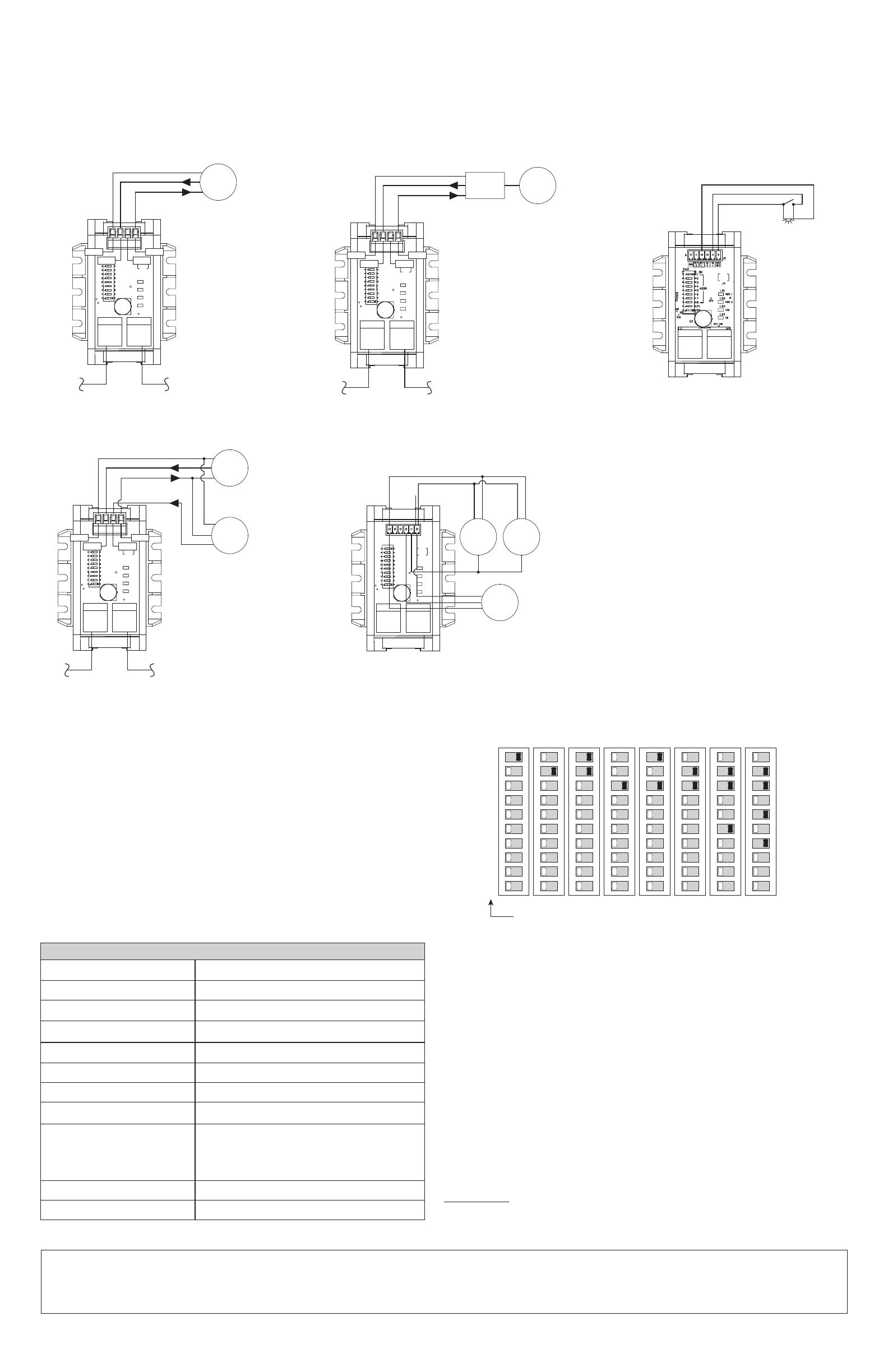
1. Wire the device and make all network connections. Some examples are shown, but your
specific situation may warrant slightly different wiring. Refer to your submittal drawings or
consult factory if you are unclear about connections means and methods.
2. Set unique LumaCAN network address (see DIP switch designations below).
3. Program the analogue interface using a GreenMAX DRC room controller
through the GreenMAX DRC System app.
NOTE:
Devices are powered from the LumaCAN network and power is passed through the AI + 24Vout/COM
terminals. Ensure you have adequate power to power all devices before connecting to the network.
NOTE: LumaCAN network must be powered by Class 2 or LPS power supply and total network power may
not exceed 1500mA per power segment.
12345678
ON
1
2
4
8
16
32
64
128
Switch Values
ID Address Value = Sum of Switch Values
ID 86 = 2+4+16+64
12345678
ON
ID 2ID 1
12345678
ON
ID 3
12345678
ON
ID 4
12345678
ON
ID 5
12345678
ON
ID 6
12345678
ON
ID 38
12345678
9
P1
9
9
9
9
9
9
9
10
P2
10
10
10
10
10
10
10
ON
ID 86
Wiring and Network Details
For Technical Assistance Call: 1-800-824-3005 (USA Only) or 1-800-405-5320 (Canada Only) www.leviton.com
• All devices on a LumaCAN network require a unique address. This device supports
Auto-Addressing which is the preferred method of address assignment.
• A GreenMAX DRC Room Controller will assign a unique address to all devices on the
network.
• For Auto-addressing to work, all dip switches must be set to OFF.
• Both AI1/AI2 LED’s will blink when the devices has no address, and, will stop blinking
when a valid address is assigned.
• If you prefer to set an address manually, please use the dip switches to assign a fixed
address.
LIMITED 5 YEAR WARRANTY AND EXCLUSIONS
Leviton warrants to the original consumer purchaser and not for the benefit of anyone else that this product at the time of its sale by Leviton is free of defects in materials and workmanship under normal and proper use for five years from the
purchase date. Leviton’s only obligation is to correct such defects by repair or replacement, at its option. For details visit www.leviton.com or call 1-800-824-3005. This warranty excludes and there is disclaimed liability for labor for removal
of this product or reinstallation. This warranty is void if this product is installed improperly or in an improper environment, overloaded, misused, opened, abused, or altered in any manner, or is not used under normal operating conditions or not
in accordance with any labels or instructions. There are no other or implied warranties of any kind, including merchantability and fitness for a particular purpose, but if any implied warranty is required by the applicable jurisdiction, the
duration of any such implied warranty, including merchantability and fitness for a particular purpose, is limited to five years. Leviton is not liable for incidental, indirect, special, or consequential damages, including without limitation, damage
to, or loss of use of, any equipment, lost sales or profits or delay or failure to perform this warranty obligation. The remedies provided herein are the exclusive remedies under this warranty, whether based on contract, tort or otherwise.
Wiring to a Single Photocell: Wiring to a Demand Response Interface: Wiring to Switch:
LumaCAN
Common
0-10VDC
+V
Photocell
Com
A1
+V
A2
Internet
Demand
Response
Interface
LumaCAN
Common
Load Shed Trigger
+V
Com
A1
+V
A2
Wiring to (2) Occupancy Zones:
LumaCAN
Com
A1
+V
A2
Common
Occupancy Signal
+V
Zone 1
Occupancy
Sensor
Zone 2
Occupancy
Sensor
Occupancy
Sensor 1
Occupancy
Sensor 3
Occupancy
Sensor 2
Wiring to (3) Occupancy Sensors:

