DI-000-OSR05-04B
© 2020 Leviton Mfg. Co., Inc.
6. Confirm sensor is operating on network.
7. Install sensor into mounting hole. a. Retract spring arms and
insert into mounting hole.
b. Release spring arms, sensor will secure itself.
FCC COMPLIANCE STATEMENT:
The enclosed device complies with Part 15 of the FCC Rules. Operation is subject to the following two conditions:
(i.) This device may not cause harmful interference (ii.) This device must accept any interference received, including
interference that may cause undesired operation. Any changes or modifications not expressly approved by Leviton could
void the user’s authority to operate this equipment. This equipment has been tested and found to comply with the limits
for a Class B digital device, pursuant to part 15 of the FCC Rules. These limits are designed to provide reasonable
protection against harmful interference in a residential installation. This equipment generates uses and can radiate radio
frequency energy and, if not installed and used in accordance with the instructions, may cause harmful interference to radio
communications. However, there is no guarantee that interference will not occur in a particular installation. If this equipment
does cause harmful interference to radio or television reception, which can be determined by turning the equipment off and
on, the user is encouraged to try to correct the interference by one or more of the following measures:
• Reorient or relocate the receiving antenna.
• Connect the equipment into an outlet on a circuit different from that to which the receiver is connected.
• Increase the separation between the equipment and receiver.
• Consult the dealer or an experienced radio/TV technician for help.
INDUSTRY CANADA COMPLIANCE STATEMENT:
This device complies with Industry Canada license-exempt RSS standard(s).
Operation is subject to the following two conditions: (1) this device may
not cause interference, and (2) this device must accept any interference,
including interference that may cause undesired operation of the device.
IMPORTANT! Any changes or modifications not expressly approved by the
party responsible for compliance could void the user’s authority to operate
this equipment. This Class B digital apparatus complies with Canadian CAN
ICES-3(B)/NMB-3(B).
RF EXPOSURE AND CO-LOCATION:
To comply with FCC OET Bulletin 65 and ISED RF exposure limits for
general population / uncontrolled exposure this device should be installed
and operated with a minimum distance of 7.9 inches (20 cm) between the
radiator and your body. This transmitter must not be co-located or operated
in conjunction with any other antenna or transmitter.
5. Manual address assignment (not required with GreenMAX DRC system, see note above).
Set DIP switches 1-8 to the desired LumaCAN address
A unique LumaCAN address ID must be set for each LumaCAN device. The first 8 switches of the DIP switch are used for setting the ID. During operation,
P1 and P2 must be in the off position. Valid node addresses are 1-250. If the node ID’s are defined in your Contract Document, set to that address. If not,
ensure that the ID is unique for each device in the system. It’s helpful, although not required, that the location of each node ID is documented for
use by Leviton Field service during system commissioning.
4. Manual input number assignment (not required with GreenMAX DRC system, see note above).
Using the DIP switches and procedures below, program the universe and input numbers into the sensor
Each sensor requires a unique input number assignment. This input number will be used by the network controller(s) to track activity of the sensor.
The occupancy sensor will have the assigned input number and the photocell will have the next sequential number (If occ sensor is 1, photocell
is 2). Setting the input number requires setting the universe number and the input number within that universe. Valid universe numbers are 0-127,
resulting in a input number range of 1-32,768. The chart shows each universe number, the channel range for that universe, the DIP switch setting
for the universe, and the actual input number.
3. LumaCAN Address
• All devices on a LumaCAN network require a unique address, and, sensors require a unique Input. This device supports auto-addressing and
auto-configuration which is the preferred method of address assignment.
• A GreenMAX DRC Room Controller will assign a unique address to all devices on the network.
• For auto-addressing to work, all dip switches must be set to OFF.
• Both pilot LED's will blink when the devices has no address and will stop blinking when a valid address is assigned.
• If you prefer to set an address manually, please use the dip switches to assign a fixed address and input number per #4 and #5 below.
1. Set the Universe Number
a. Set DIP switch P1 to [ON]
b. The PWR indicator should blink
rapidly indicating that the Smart Pack
is awaiting entry of the universe
number.
c. Set DIP switches 1-8 to the required
address of the universe number.
Refer to the chart.
d. For input numbers between 1-256 it
will be set to all 0’s.
e. Set DIP switch P1 to [OFF]
f. The PWR indicator will turn off
indicating that it is saving data then
resume normal operation.
2. Set the Input Number
a. Set DIP switch P2 to [ON]
b. The COM indicator should
blink rapidly indicating that it is
awaiting an input number.
c. Set DIP switches 1-8 to the
required address of the input
number. Refer to the chart.
d. Set DIP switch P2 to [OFF]
e. The COM indicator will turn off
indicating that it’s saving data
then resume normal operation.
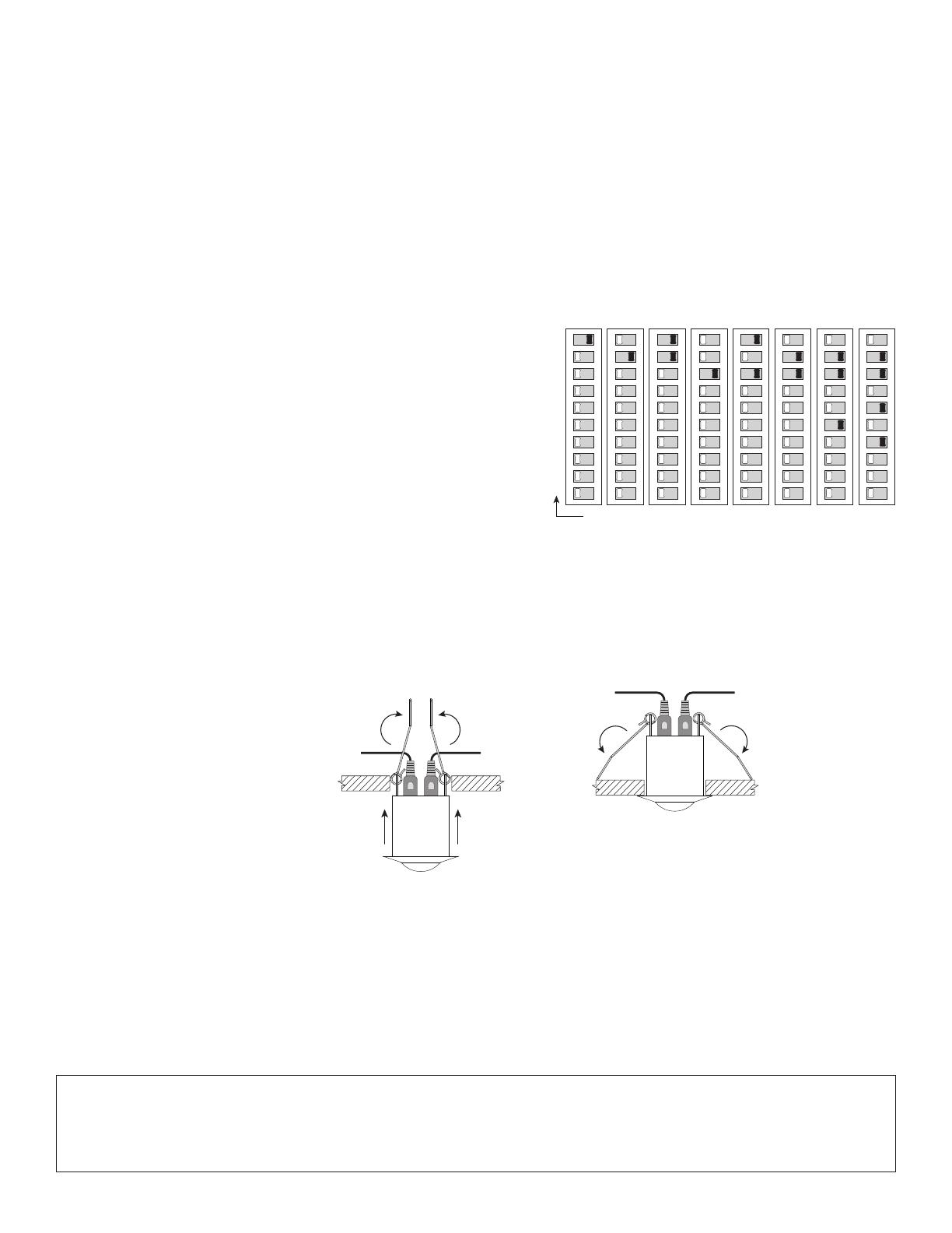
12345678P1P2
ON
1
2
4
8
16
32
64
128
Switch Values
ID Address Value = Sum of Switch Values
ID 86 = 2+4+16+64
12345678P1P2
ON
ID 2ID 1
12345678P1P2
ON
ID 3
12345678P1P2
ON
ID 4
12345678P1P2
ON
ID 5
12345678P1P2
ON
ID 6
12345678P1P2
ON
ID 38
12345678P1P2
ON
ID 86
For Technical Assistance Call: 1-800-824-3005 (USA Only) or 1-800-405-5320 (Canada Only) www.leviton.com
LIMITED 5 YEAR WARRANTY AND EXCLUSIONS
Leviton warrants to the original consumer purchaser and not for the benefit of anyone else that this product at the time of its sale by Leviton is free of defects in materials and workmanship under normal and proper
use for five years from the purchase date. Leviton’s only obligation is to correct such defects by repair or replacement, at its option. For details visit www.leviton.com or call 1-800-824-3005. This warranty
excludes and there is disclaimed liability for labor for removal of this product or reinstallation. This warranty is void if this product is installed improperly or in an improper environment, overloaded, misused,
opened, abused, or altered in any manner, or is not used under normal operating conditions or not in accordance with any labels or instructions. There are no other or implied warranties of any kind, including
merchantability and fitness for a particular purpose, but if any implied warranty is required by the applicable jurisdiction, the duration of any such implied warranty, including merchantability and fitness for a
particular purpose, is limited to five years. Leviton is not liable for incidental, indirect, special, or consequential damages, including without limitation, damage to, or loss of use of, any equipment,
lost sales or profits or delay or failure to perform this warranty obligation. The remedies provided herein are the exclusive remedies under this warranty, whether based on contract, tort or otherwise.
FOR CANADA ONLY
For warranty information and/or product returns, residents of Canada should contact Leviton in writing at Leviton Manufacturing of Canada ULC to the attention of the Quality Assurance Department,
165 Hymus Blvd, Pointe-Claire (Quebec), Canada H9R 1E9 or by telephone at 1 800 405-5320.

