Page is loading ...

Page 1 of 16
Air Techniques, Inc.
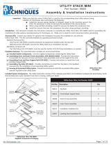
UTILITY STACK XL
Part Number: 56650
Assembly & Installation Instructions
Components of Ulity Stack XL, Part Number 56650
Part No. Descripon Qty
56623 Top Rails 2
56624 Front & Rear Support Rails 2
56638 Outer Frame Assembly 2
56639 Inner Frame Assembly 2
56615 Installaon Hardware Kit 1
55487 Leveling Foot Installaon Kit 1
Utility Stack XL, P/N 56650
Accessory Kits. Contact your dealer for optional accessory kits available for use with the Ulity Stack XL.
Optional Accessory Kits -
Drip Tray Kit, P/N 56655: provides protection to equipment installed under the top rails.
Wall Mount Kit, P/N 54145: secures the Ulity Stack to an installation site wall.
Procedure Summary. The assemble tasks included are summarized below:
q Included System Components. Lists the supplied components comprising the Ulity Stack.
q Assembling Inner and Outer Frame Assemblies, P/N 56638 & 56639. Provides the instrucons to assemble the two pairs of
Inner and Outer Frame assemblies and set the height of the rack.
q Assembling Front and Rear Support Rails P/N 56624. Provides instrucons to install the Front and Rear Support Rails.
q Assembling Top Rails P/N 56623. Provides instrucons to install the Top Rails in the locaons necessary for the installaon of
corresponding ulity system.
q Securing Associated Ulity System. Provides instrucons to install the associated ulity system onto the Top Rails of the Ulity
Stack.
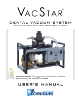
Included System Components. The Ulity Stack XL consists of the indicated assemblies and installation hardware kits listed below. Verify
that all listed items were received. If any item is missing, notify your dealer.
Important: Make sure that the correct Utility Stack is used for the corresponding sized utility systems being
installed. Air Techniques also recommends the following:
Install the vacuum pumps (VacStar or Mojave) closest to the incoming vacuum line
(from the operatory) in order to decrease the workload of the vacuum pump.
When using sub-oor plumbing, install the vacuum line below the compressor line.
Install the vacuum line over the compressor line when using overhead plumbing.
Introduction. This document provides the instructions necessary to assemble the Ulity Stack XL, P/N 56650 used to consolidate the
installation of utility systems manufactured by Air Techniques, Inc. Make sure to read this entire document before proceeding.
Utility Stack XL, P/N 56650
Supplied Components & Packaging
Packing
Material
Inner
Frame Assembly
P/N 56639
Packing
Material
Inner
Frame Assembly
P/N 56639 Outer
Frame Assembly
P/N 56638
Top Rails
P/N 56623
Front & Rear
Support Rails
P/N 56624
Outer
Frame Assembly
P/N 56638
Packing
Material
Packing
Material

Page 2 of 16 Air Techniques, Inc.
Use Code A: Idenes fastening hardware used to assemble the Ulity Stack XL for use.
Use Code I: Idenes fastening hardware used to install applicable ulity system onto the
assembled Ulity Stack XL.
Installaon Hardware Kit, Part Number 56615
Use Code
(See Note) Part No. Part Descripon Quanty
A 31536 Bolt, ⅜-16 X 2-¾ inch 4
I30007 Bolt, ⅜-16 X 2 inch 4
A & I 30803 Bolt, ¼-20 X ½ inch 20
A 31854 Cap Plug, Ø 0.234 X ½ inch 16
A30128 Nut, ⅜-16 8
A & I 30049 Nut, ¼-20 20
I84106 Rubber Washer, 7/16 inch 4
A & I 30164 Washer, ⅜ inch 16
I30610 Washer, ¼ inch 4
A30324 Lock Washer, ⅜ inch 8
A & I 30222 Washer, ¼ inch, Lock 28

Page 3 of 16
Air Techniques, Inc.
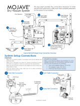
Assembling Inner and Outer Frame Assemblies, P/N 56638 & 56639. Assemble the two pairs of Inner and Outer Frame Assemblies to
form the le and right side supports by performing the following steps.
1. Slide the Inner Frame into the Outer Frame and install Leveling Feet onto each side of the Inner Frame.
2. Refer to Table 1 (Page 4) to set the height of the top shelf for the equipment conguraon being installed. This is done by sliding the
edges of Outer Frame to one of the three height posion sengs on the Inner Frame marked by 1, 2 or 3 dots.
3. Secure the seng with the supplied height locking hardware listed below.
Inner Frame
P/N 56639
Note: Leveling feet add a minimum of 1 inch when
set in the lowest posion and a maximum of
2 inches at the highest seng.
1
Outer Frame
P/N 56638
2
2Leveling Foot Installaon Hardware
Item Descripon Part No. Quanty
1 Leveling Foot 85473 4
2⅜-16 Nut 30128 8
Leveling Foot
Installaon Detail
Height Locking Hardware (both sides)
Item Descripon Part No. Quanty
12 to 3 inch Bolt 31536 4
2⅜ Washer 30164 8
3⅜ Lock Washer 30324 4
4⅜-16 Nut 30128 4
Important:
Refer to page 4, table 1 for the height level of
the top shelf required for the ulity equipment
conguraon being installed.
Upper Height
3 Dots
41-3/8 Inches
12
1
23
4
2
23
4
Height Seng
Detail
Medium Height
2 Dots
36-3/8 Inches
Lower Height
1 Dot
29-3/8 Inches

Page 4 of 16 Air Techniques, Inc.
Ulity Stack XL
Shelf Height Posion AirStar AirStar NEO VacStar VacStar NEO Mojave
Lower 1 Dot - 30” 3/8 VS50
VS80
VS50NEO
VS80NEO
LT3
V3
V5
V7
Middle 2 Dots - 37” 3/8
AS30
AS40
AS50
AS30NEO VS50H
VS80H
V3 & MT10
V5 & MT10
V7 & MT10
Upper 3 Dots - 41” 3/8
AS30C
AS40C
AS50C
AS70
AS70C
AS100
AS50NEO
AS70NEO
Notes:
1. Mojave V3, V5, 2V3 & 2V5 systems are always installed on the upper shelf.
2. Mojave CT20 tanks are never installed on a Ulity Stack.
3. All height levels are approximate and are based on seng the leveling feet in the lowest posion.
4. The height level will increase by approximately one (1) addional inch when the leveling feet are set in the Highest posion.
5. Use drip tray when any VacStar is installed on the top shelf.

Page 5 of 16
Air Techniques, Inc.
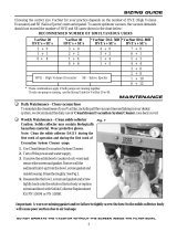
Assembling Front and Rear Support Rails P/N 56624. Each support rail is designed to aach to both sides of the associated side supports
of the rack. Slots on one side slide into threaded studs and are secured by nuts while the threaded holes on the other side are secured
with bolts. Install the Front and Rear Support Rails between the le and right side supports formed by the two pairs of assembled Inner
and Outer Frame assemblies by performing the following steps.
1. Align the two slots at both ends of the Support Rail with the threaded studs on the frame and slide the rail onto the studs.
2. Loosely install the supplied lock washers (P/N 30222) and nuts (P/N 30049) to the threaded studs on both frames.
3. Secure each Support Rail by installing the bolts (P/N 30803) and lock washers (P/N 30222) into the two threaded
holes on both frames.
4. Tighten the nuts (P/N 30049) on the threaded stud side on both frames.
5. Install the 16 supplied Cap Plugs (P/N 31854, not shown) onto all exposed unused threaded studs
Threaded
Studs
Threaded
Studs
Threaded
Holes
Rear Support
Rail
Outer Frame
Assembly
P/N 56638
Inner Frame Assembly
P/N 56639
Front Support Rail
(posioned high on side supports)
Rear Support
Detail
Front Support
Detail
Front & Rear Support Rail installaon Hardware
Item Descripon Part No. Quanty
1½ Inch Bolt 30803 8
2¼ Inch Lock
Washer 30222 16
3Nut 30049 8
4¼ - 20 Cap Plug 31854 16
1
2
3
2
3
2
1
2
Correct Support Rail Assembly
Front
Support Rail
Installed on top-front
threaded studs.
Rear
Support Rail
Installed on mid-level
rear threaded studs.
Slots
Slots

Page 6 of 16 Air Techniques, Inc.
Assembling Top Rails P/N 56623. Install the Top Rails in the locaon shown for the applicable ulity system being installed onto the Utility
Stack. Note that the posion of each Top Rail is dependant on the ulity system being installed. Make sure to locate each rail as shown.
Secure the rails with the supplied hardware listed on page 3 by performing the following steps.
1. Align the holes of both ends of the Top Rail being installed with the holes of the Le and Right Side Supports making sure to locate each
rail as shown (correctly numbered hole and/or slot locaons) for the ulity system being installed.
2. Install two bolts (P/N 30803) into the holes of both ends of the Top Rail.
3. Secure each Support Rail by installing the supplied lock washers (P/N 30222) and nuts (P/N 30049) to the bolts as shown below.
Typical Aaching Hardware Installaon Order
1
2
3
Top Rail Installaon
Hole and Slot Locaons for Top Rail Installaon
Front Support
Rail
Rear Support
Rail
B
D
A
C
Front & Rear Support Rail installaon Hardware
Item Descripon Part No. Quanty
1½ Inch Bolt 30803 8
2¼ Inch Lock
Washer 30222 16
3¼-20 Nut 30049 8

Page 7 of 16
Air Techniques, Inc.
Securing Ulity System Being Installed. Install the associated ulity system onto the Top Rails of the Ulity Stack unit. Note that the
specic slots used on each Top Rail for system installaon is dependant on the ulity system being installed.
Typical Aaching Hardware Installaon Order
Using Mulple Washers
DETAIL F
SCALE 1.5 : 1
Bolt
P/N 30803
Washer,
P/N 30610
Lock Washer
P/N 30222
Make sure to use corresponding rail slots as shown for the applicable system. Se-
cure with the required aaching hardware listed for each ulity system installaon.
Important: Make sure that each rail is located as shown. The posion of each Top Rail is dependant
on the ulity system being installed.
AirStar Securing Procedure. Refer to the drawings below and secure the AirStar unit on the properly spaced Top Rails of the Ulity Stack.
Secure the AirStar compressor by performing the following steps.
1. Remove the AirStar from its shipping pallet by removing the hardware securing each foot to the shipping pallet.
2. Orient the AirStar to be installed with its front facing forward.
3. Refer to Detail A and align the four slots of the Top Rails with the slots of the feet of the AirStar being installed.
4. Refer to Detail B and install bolt (item 1) from under the Top Rail and through the AirStar foot hole.
5. Secure each foot of the compressor to the rails by installing rubber washer (item 2), washer (item 3) lock washer
(item 4) and nuts (item 5) to the bolts. Tighten all nuts.
AirStar & AirStar NEO Securing Hardware
Item Descripon Part No. Quanty
12-inch Bolt 30007 4
2Rubber Washer 84106 4
3⅜ Washer 30164 8
4⅜ Lock Washer 30324 4
5⅜-16 Nut 30128 4
Detail A
Typical AirStar Installaon
on Top Posion of Ulity
Stack
Important: If equipment is not shown, refer to page 11 for dimensions
AirStar & AirStar NEO Securing Hardware
AirStar compressors are mounted on the Top Rails of the Ulity Stack at corresponding locaons as shown by the AirStar Securing Posion
Views above.
AirStar Compressor Posion Views
AirStar 70
AirStar 30
AirStar 30
Footprint
(See note)
CC CC
CC
AirStar 50
AirStar 50
Footprint
CC CC AirStar 70
Footprint CC
CC
10 ¾ in.
14 in.
AirStar 30
Shown
Detail B
Typical AirStar & AirStar NEO Hardware Installaon
on Top Posion of Ulity Stack
CC
3
1
5
2
4Top
Rail
AirStar
NEO
AirStar
Top
Rail
3
3
1
5
2
4
3
Top Rail Slot Locaons for Various Utility System Installaons
Ulity Stack Front
DD
EE
AA BB DD
CC AA
BBCC
Note: Same footprint
for AirStar models
AS21, AS22 & AS40

Page 8 of 16 Air Techniques, Inc.
V3, V5 or V7 Pump and MT10 Tank Securing Locaon
Mojave V3 / V5 / V7 pumps and the MT10 tank are mounted onto the Top
Rails at corresponding locaons shown above.
Securing Hardware
Both the pump and tank frames are secured to the front rail using the hard-
ware supplied with the pump Accessory Pack, P/N H5170. The hardware
supplied with the Installaon Hardware Kit, P/N 56615, (See page 2 for list).
is used to secure either frame to the rear rail.
V3, V5 or V7 Pump Securing Procedure. Install the Mojave pump as follows.
1. Remove the four leveling feet from the pump frame.
2. Orient the pump to be installed with the unit facing forward.
3. Align the le and right front corner threaded holes of the pump frame with
holes DD and AA of the front top rail as shown above and to the right.
4. Install bolts, washers and lock washers supplied with the pump into the two
front corner threaded holes of the pump frame.
5. Install bolts, washers, lock washers and nuts supplied with Kit, P/N 56615
into the pump frame holes aligned with the rear rail screw holes DD and AA.
6. Secure the pump to the rails by ghtening the two front bolts and two
rear nuts.
MT10 Tank Securing Procedure. Secure MT10 tank as follows:
1. Remove the four leveling feet from the tank frame.
2. Orient the tank to be installed with the unit facing forward.
3. Align the le and right front corner threaded holes of the tank frame with
holes AA and DD of the Front Top Rail as shown above and to the right.
4. Install bolts, washers and lock washers supplied with the tank into the two
front corner threaded holes of the tank frame.
5. Install bolts, washers, lock washers and nuts supplied with Kit, P/N 56615
into the tank frame holes aligned with the rear rail screw holes AA and DD.
6. Secure the tank to the rails by ghtening the two front bolts and two
rear nuts.
Important: Make sure that each rail is located as shown. The posion of each Top Rail depends on
the ulity system to be installed.
Mojave Securing Procedure. Install the V3, V5 or V7 Pump and MT10 Tank units on the properly spaced Top Rails of the Ulity Stack.
Mojave V3, V5 or V7 Pump and MT10 Tank Posion View
AA
DD
Front
Top
Rail
V3, V5 or V7
Pump
MT10
Tank
AA
DD
Rear Rail Securing Hardware
(Use with pump and tank frame rear screw holes.)
Descripon Part No. Quanty
¼-20 X ¾ inch Bolt 30803 4
¼ inch Washer 30610 4
¼ inch Lock Washer 30222 4
Supplied with Installaon Hardware Kit, P/N 56615
Front Rail Securing Hardware
(Use with pump and tank frame front threaded screw holes.)
Descripon Part No. Quanty
¼-20 X ½ inch Bolt 30914 4
¼ inch Washer 30958 4
¼ inch Lock Washer 30920 4
Supplied with pump Accessory Pack, P/N H5170
Rear
Top
Rail
AA
MT10 Tank
Footprint AA
DD DD
V3 & V5 Pump
Footprint
Pump Front
D
A
Tank Front
D
A
15 in.

Page 9 of 16
Air Techniques, Inc.
Acadia Amalgam Separator Mounng Opons.
Acadia Oponal Mounng Area
(Front Le or Rear of Ulity Stack)
Mount the Acadia without Chassis/Mounng Bracket
(Front Le or Rear of Ulity Stack)
Remove the
Chassis/Mounng Bracket
Chassis/Mounng
Bracket
Acadia Amalgam Separator Mounng Opons.
The Acadia, when used, can be placed on the floor, hung on a wall or mounted to the front side (le or right) of the Ulity Stack. Please
note that regardless of the installaon opon chosen the Separator must be level, securely mounted and located between the output of
the facility Treatment Operatory and the Vacuum System Input. Refer to the instrucon manual (P/N A1301) supplied with the Acadia unit.
The Acadia is le in its Chassis/Mounng Bracket when installing it on the ulity room wall or floor. Floor installations require that the
Separator simply be set on floor in a location convenient to system connections and for service access. When installing the Acadia on
an exisng ulity room wall, the unit must be placed in a location that allows easy system connection and service access. The Separator,
in its Chassis/Mounng Bracket, is secured to the wall using lag bolts provided by the installer.
When hanging the Acadia on the front side of the rack, the Chassis/Mounng Bracket must be removed as shown by the drawing below.
The Acadia is then installed on the selected front (le or right) area using the same mounng area and hardware (4 screws and washers)
that secured the unit to the Chassis/Mounng Bracket.
Important: Make sure that each rail located as shown. The posion of each Top Rail is dependant
on the ulity system to be installed.
VacStar 80 Securing Procedure. Install the VacStar on the properly spaced Top Rails of the Ulity Stack.
VacStar 80 Securing Posion Views
VacStar 80 Securing Hardware
VacStar 80 units are mounted on top of the Top Rails at corresponding locaons as
shown above. The VacStar frame is secured using the aaching hardware supplied with
this Kit, P/N 56615.
Secure the VacStar 80 unit by performing the following steps.
1. Orient the pump to be installed with its front facing forward.
2. Refer to the VacStar 80 securing Posion View above and align the rear holes of the
VacStar with the slots (CC & PP) of the Top Rails.
3. Install four bolts (item 1) and washers (item 2) into the corresponding holes of the
VacStar frame and the Top Rail as shown by Details A & B.
4. Refer to Detail A and secure the pump to the rails by installing a washer (item 2), lock
washer (item 3) and nut (item 4) to each installed bolts. Tighten all nuts.
VacStar 80 Footprint CC
Front of Unit
CC
13 in.
VacStar 80 Securing Hardware
Item Descripon Part No. Quanty
1Bolt 30803 4
2Washer 30610 4
3Lock Washer 30222 4
Hardware supplied with Kit, P/N 56615
Securing Hardware Installaon Order
DETAIL F
SCALE 1.5 : 1
3
1
2

Page 10 of 16 Air Techniques, Inc.
19
3
4
"
25"
5
1
8
"
6
1
2
"
11"
9
1
2
"
1
2
"
32
1
2
"
20"
5"
8
1
4
"
10
3
4
"
14"
1
2
"
35
1
2
"
21"
4
1
4
"
8
3
4
"
18"
14"
3
8
"
47
1
4
"
23
1
4
"
5
1
8
"
15
1
8
"
20"
14
1
8
"
5
8
"
46"
24"
5
1
8
"
10
7
8
"
20"
14
1
8
"
5
8
"
27
3
4
"
16
5
8
"
2
1
8
"
1
2
"
26
5
8
"
13"
1
4
"
VS20 / VS40
VS50 / VS50H / VS80 / VS80H
11
5
8
"
11
3
8
"
2
3
4
"
6
3
4
"
11
5
8
"
11
5
8
"
3" 4"
7"
6
7
8
"
2"
AS10 / AS12
AS21 / AS22 / AS30/ AS40
AS70
AS100
AS50
VS20 NEO / VS40 NEO

Page 11 of 16
Air Techniques, Inc.
24
3
4
"
20
7
8
"
1
3
8
"
1"
22
3
4
"
15"
1
4
"
24"
16
1
4
"
1
3
8
"
5
8
"
22
5
8
"
13
1
2
"
1
4
"
24
3
4
"
20
5
8
"
4
1
4
"
1"
22
3
4
"
15"
1
4
"
26
1
4
"
19
3
4
"
3
3
8
"
7
3
4
"
11"
11"
AS21NEO / AS22NEO / AS30NEO
AS40NEO / AS50NEO
AS70NEO
AS10NEO
26
1
4
"
19
3
4
"
5
1
2
"
7
3
4
"
11"
11"
30
3
4
"
21
1
4
"
6
1
8
"
8
5
8
"
13
1
2
"
11
3
4
"
47
7
8
"
20
3
4
"
6
1
8
"
11" 26"
11
3
4
"
A
1
2
"
3
8
"
DETAIL A
V3/ V5 / V7
MT10 / CT20
LT3

Page 12 of 16 Air Techniques, Inc.
Typical Utility Stack Installation
(AirStar AS70 mounted on top with Acadia
and VacStar VS80H on bottom)
Typical Utility Stack Installation
(Two Mojave V3 units mounted on top with AirStar
AS50 mounted on bottom)
AirStar AS50
Mojave V5
MT10 Tank
AirStar AS70
VacStar
VS80H
Acadia
Typical Utility Stack Installation
(Mojave V5 mounted on top with AirStar AS50
mounted on bottom)
AirStar AS50
MT10 Tank
Mojave V3

Notes


Air Techniques, Inc. © Copyright 2011 • P/N 56686 Rev. F - May 2021
Acadia, AirStar, Mojave and VacStar are all registered
trademarks of Air Techniques, Inc.
q Digital Imaging
• Digital Radiography
• Intraoral Camera
• Caries Detection Aid
• Intraoral X-ray
• Film Processors
q Utility Room
• Dry Vacuums
• Wet Vacuums
• Air Compressors
• Amalgam Separator
• Utility Accessories
• Utility Packages
q Merchandise
• Evacuation System Cleaner
• Imaging Accessories
• Chemistry
• Processor Accessories
For over 50 years, Air Techniques has been a leading innovator and manufacturer of dental
products. Our priority is ensuring complete satisfaction by manufacturing reliable products
and providing excellent customer and technical support. Whether the need is digital imaging,
utility room equipment or merchandise, Air Techniques can provide the solution via our network
of authorized professional dealers. Proudly designed, tested and manufactured in the U.S., our
products are helping dental professionals take their practices to the next level.
Air Techniques’ family of quality products for the dental professional include:
Corporate Headquarters
1295 Walt Whitman Road | Melville, New York 11747- 3062
Phone: 800-247-8324 | Fax: 888-247-8481
www.airtechniques.com
/