Page is loading ...


Dear Customer,
We thank you for having chosen one of our products, the fruit of extensive and continuous research for a superior product in terms of safety, reliability
and performance.
In this manual you will nd all the information and advice you need to use your product as safely and efciently as possible.
ESSENTIAL INSTRUCTIONS
•This instruction booklet has been prepared by the manufacturer and is
an integral part of the product. In the event of sale or relocation of the
product make sure this booklet accompanies it, since the information
contained in it is addressed to the purchaser and to anyone involved
in the installation, use and maintenance of the product.
•Read the instructions and the technical information contained in
this manual carefully, before proceeding with installation, use or any
repairs.
•Compliance with the instructions in this booklet guarantees the safety
of persons and of property; it also ensures more efcient operation
and an increased lifespan.
•Gruppo Piazzetta S.p.A. declines all responsibility for damage caused
by failure to observe the installation, use and maintenance instructions
in this manual, for unauthorized product modications or for use of
non-original spare parts.
•Gruppo Piazzetta S.p.A. will not be responsible for defects and damage
resulting from modications or tampering of the product including
changing the value of one or more parameters that determine
operation. Any changes, including changing the original parameters,
may only be carried out by authorised persons from the company and
with the values set by the manufacturer
•The installation and use of the product must be made in accordance
with the manufacturer's instructions and in compliance with European,
national and local regulations.
•The installation, electrical connection, operational check, maintenance
and repairs are operations that must be performed by qualied and
licensed technicians that have appropriate knowledge of the product.
•The wall against which the product is to be placed must not be of
wood or any other ammable material. For correct installation it is
also important to follow the indications given in the section entitled
“MINIMUM SAFETY DISTANCES”.
•Read all the instruction manuals relating to: the cladding, the
ventilation kit and any other accessories.
•Check that the oor where the product is to be installed is completely
level
•When handling the steel parts of the cladding it is advisable to use
clean cotton gloves to avoid leaving ngerprints which are difcult to
remove at rst time of cleaning.
•The stove must be assembled by at least two people.
•Connect the pellet stove to the electricity network only after having
correctly connected it to the ue.
•The plug must always be accessible after the stove has been installed.
For the restrictions, limitations and exclusions please refer to the warranty included with the product.
In line with its policy of constant product improvement and renewal, the manufacturer may make changes without notice.
This document is the property of Gruppo Piazzetta S.p.A.; no part of it may be disclosed to third parties without the written permission of
Gruppo Piazzetta S.p.A. All rights reserved by Gruppo Piazzetta S.p.A.
•When operating the pellet stove only use wood pellets which conform
to standards (see the chapter entitled “FUEL”).
•Do not use liquid fuel to operate the pellet stove or to stoke the embers.
•Make sure there is adequate ventilation during operation in the room
where the product is installed.
•The fuel supply is interrupted if the product shows any signs of
malfunctioning. Only restart the product after having eliminated the
cause of the malfunction.
•Stop using the product in the event of a fault or malfunction.
•Do not remove the protection grille which is located on the pellet tank.
•The accumulation of pellets in the brazier following several failed light
up attempts (no lit) must be removed before lighting.
•Pellet stove operation may cause the surface, the handles, the ue
and the glass to become extremely hot. Only touch these parts during
operation if wearing the correct protective clothing or with suitable
means.
•Since the glass becomes hot, make sure that no person other than
those experienced in operating the stove remain in the installation
area.
•This appliance is not for use by persons (including children) with
reduced physical, sensory, mental capacity or with a lack of experience
and knowledge, unless they have been instructed on how to use the
appliance by the person who is responsible for its safety
•During the operation and/or cooling phase, slight creaking noises may
be heard. This is not considered a defect, but is a consequence of the
thermal expansion of the materials used.
•The images shown in this manual are for explanatory purposes and at
times may not accurately depict the product.
a If there are any problems or difculties in understanding the
manual, contact the local dealer.
a If the ue should catch re or in the case of other dangerous
situations, stop using the appliance, do not open the door,
switch the appliance off, take all necessary safety actions and
contact the emergency services.
d It is forbidden to place objects which are not heat-resistant on
the stove or within the prescribed minimum safety distance.
d Do not open the door during operation, or operate the stove if
the glass is broken.
H072043UK0 / DT2001455 - 00
2
English
DT2010208-11
DT2010001-01

1.0 GENERAL INDICATIONS 4
1.1 Single chimney or flueway 5
1.2 Soot inspection 5
1.3 Chimney 6
1.4 Fresh air intake 7
1.5 Installation environment 7
1.6 Load-bearing capacity of the floor 8
1.7 Heating capacity 8
1.8 Smoke outlet pipe 8
1.9 Connection to the traditional type flue 10
1.10 Fresh air intake 11
1.11 Prevention of domestic fires 11
1.12 Minimum safety distances 12
2.0 TECHNICAL DATA AND SPECIFICATIONS 13
2.1 Characteristics 13
2.2 Product identification data 13
2.3 Technical data 14
2.4 Accessories supplied 14
2.5 Dimensions P937 15
3.0 FUEL 16
4.0 PREPARATION FOR INSTALLING 17
5.0 INSTALLATION 18
5.1 Multifuoco system 18
5.2 Electrical connections and control devices 22
5.3 Installation of the external thermostat 23
5.4 Smoke outlet 23
6.0 USE 24
6.1 Loading the pellets 24
6.2 Pellet LCD remote control 25
6.3 First start-up 26
6.4 Start-up and normal functioning 27
6.5 Possible problems and solutions 31
6.6 Control panel 35
6.7 Setting the Language 36
6.8 Programming 37
6.9 Setting the clock 38
6.10 Thermostat 39
6.11 Fan mode 45
6.12 Multicomfort 45
6.13 Energy Saving 46
6.14 Parameter menu 48
6.15 Enable Beep (audio signal) 50
6.16 Modifying the transmission unit 50
6.17 State stove 51
6.18 Multifuoco System Operation 51
6.19 Safety devices 52
6.20 Opening the door 56
6.21 Stove humidifier 56
6.22 Disposal of ash 56
7.0 MAINTENANCE 57
7.1 Cleaning the brazier and brazier support 57
7.2 Cleaning the ash tray 57
7.3 Cleaning the combustion chamber 58
7.4 Cleaning the smoke chamber 58
7.5 Cleaning the flue system 59
7.6 Cleaning the ceramic cladding 59
7.7 Cleaning the steel parts 59
7.8 Cleaning the glass (daily) 59
7.9 Replacing the glass 60
7.10 Replacing the remote control battery 60
7.11 Cleaning the fans 61
7.12 When not in use: 61
7.13 Scheduled maintenance 62
8.0 MAIN ANOMALIES 63
8.1 Replacing the fuses 65
European Standards 66
Reference Standards 66
CONTENTS
Chapter Heading Page
This booklet code H072043UK0 / DT2001455 - 00 (05/2013) comprises 68 pages.
H072043UK0 / DT2001455 - 00 3
English
DT2010187-00

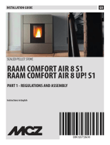
Check that the installation of your product conforms to all the indications given below.
SOOT INSPECTION APERTURE
CHIMNEY STACK
CHIMNEY
CONNECTION
TO FLUE
MINIMUM SAFETY
DISTANCES
CAPACITY LOAD
OF THE FLOOR
FRESH AIR INTAKE
FLUEWAY
ELECTRIC
POWER SUPPLY
Fig. 1
1.0 GENERAL INDICATIONS
H072043UK0 / DT2001455 - 00
4
English
DT2010216-05
DT2030321-01

MAX 45°
NO
MIN 3.5 M
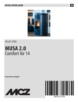
Every appliance must have a vertical pipe, called ue, operating by
natural draught to discharge the combustion gases outside.
The ue must:
- comply with regulations in force in the country where the appliance
is to be installed;
- be tight to the products of combustion, waterproof, suitably insulated,
made with materials resistant to the corrosion of the gases and to
stress;
- be connected to just one stove, replace or extraction hood (Fig. 2);
- be properly sized,with constant free internal section, equal to or
greater than the diameter of the ue pipe of the stove and at least 3.5
m in length (Fig. 2);
- be mainly in a vertical position with deection from the axis of no
more than 45° (Fig. 2);
- be at a suitable distance from combustible or ammable materials,
ensured by an air gap or suitable insulating material;
- be of uniform internal section, preferably round: square or rectangular
sections must have rounded corners with a radius of at least 20 mm;
with a maximum ratio between the sides of 1.5 (Fig. 3-4-5);
- the walls must be as smooth as possible and with no narrowing;
bends must be regular and continuous (Fig. 6).
d It is forbidden to make xed or mobile apertures on the ue
pipe to connect appliances other than the one to which it is
already connected.
d It is forbidden to pass other air ducts or service pipes inside
the ue pipe, however large it is.
a If the ue is the incorrect size or installed other than in
compliance with the above instructions, Gruppo Piazzetta
S.p.A. cannot be held liable for malfunctioning of the product,
damage to property or injury to persons or animals.
It is recommended that the ue has a chamber for collecting solid matter and any condensate below the connection and which may be easily opened
and inspected by means of an air tight door. (Fig. 1)
Deposit of creosote
R (min.20)
NO
Ø
Deposit of creosote
R (min.20)
P
L(<1,5xP)
DT2010024-02
1.1 SINGLE ChImNEy OR fLUEwAy
DT2010031-01
1.2 SOOT INSpECTION
Fig. 2
Fig. 3
Fig. 5
Fig. 4
Fig. 6
H072043UK0 / DT2001455 - 00 5
English
DT2030049-00
DT2030050-00
DT2030189-00
DT2030188-00
DT2030190-00

The chimney is the part which is positioned on the top of the ue to ease the
dispersion of combustion products into the atmosphere.
The chimney must comply with the following requirements:
- it must have an internal section and shape the same as the ue (A);
- it must have a useful outlet section (B) of not less than twice that of the ue (A);
- the chimney stack (the part of the chimney which emerges from the roof) and
is in contact with the outside (e.g.in the case of a at roof), must be covered
with brick or tile elements and in any case it must be well insulated;
- it must be built in such a way as to prevent the penetration of rain, snow and
foreign matter into the chimney and to ensure that in the event of winds from
all directions and angle, discharge of the combustion products is assured
(chimney with anti downdraught cowl).
Recommended distances for correct chimney operation.
To ensure trouble-free operation of the chimney and allow correct dilution of the
products of combustion into the atmosphere, the chimney must be installed at
the distances given below:
- 6-8 metres from any building or other obstacles that are higher than the
chimney;
- 50 centimetres higher than any obstacles located at a distance less than 5
metres;
- outside the reux area. The size and shape of this area differ according to
the angle of inclination of the roof and it is therefore necessary to adopt the
minimum heights shown below.
Example: Check the inclination of the roof (column
α), and the anticipated
distance of the chimney from the axis of the ridge (column
A), if the distance
is greater than “A” the height of the chimney may be read in (column
H). If the
distance is less than “A” the chimney must rise above the ridge by 0.5 metres.
DT2010025-03
1.3 ChImNEy
A
B*
* B it is twice
of to A
6-8 m
FLAT ROOF
5 m or less 5 m or lessover 5 m
0.50 m
0.50 m
SLOPING ROOF
height of reflux
area Z
distance more than A
H min
distance
0.50 m above the ridge
ridge axis
at least A
α
REFLUX
AREA
BB
A
Fig. 7
Fig. 9
Fig. 10
Fig. 11
Fig. 8
Roof inclination Horizontal width of the reux
area from ridge axis
Minimum height of outlet from
roof Height of reux area
αA H Z
15° 1.85 m 1.00 m 0.50 m
30° 1.50 m 1.30 m 0.80 m
45° 1.30 m 2.00 m 1.50 m
60° 1.20 m 2.60 m 2.10 m
H072043UK0 / DT2001455 - 00
6
English
DT2030051-00
DT2030052-00
DT2030053-00
DT2030192-00
DT2030191-00

In order to operate correctly the stove/replace must have the necessary
air available provided through a fresh air intake.
The air intake must:
- have a total free cross section of at least the size indicated in the
section “TECHNICAL DATA”;
- be protected by an external grille provided it does not reduce the
recommended minimum section;
- be positioned in such a way that it is not obstructed.
The air necessary for the re may be obtained in different ways:
- through a fresh air intake direct to the room where the appliance is
installed;
- with ducting through pipes direct to the room where the appliance is
installed, increasing the recommended minimum free cross section
by at least 15%;
- from an adjacent room to that where the appliance is installed
provided the air ows freely from the outside through permanent
apertures communicating with the outside.
a The adjacent room from which the air is to be taken must
not have a low pressure compared to the exterior due to a
counter draught caused by the presence in the room where
the appliance is installed of another appliance or extractor
device.
The adjacent room must have permanent apertures which
comply with the requirements provided above.
d Combustion air must not be taken from adjacent rooms which
are used as a garage, store room for combustible material or
for activities with a risk of re.
The appliance should be installed in a location which allows safe and convenient use as well as easy maintenance. If the product being installed
requires an electrical socket, the room must also be provided with an earthed power supply in accordance with current regulations.
The room where the appliance is to be installed or adjoining rooms must comply with the following requirements:
a They must not be used as a garage, store for combustible material or for activities with a risk of re.
a They must not have a low pressure compared to the exterior due to a counter draught caused by the presence in the room where the
appliance is installed of another appliance or extractor device.
a Do not use two stoves, a replace and a stove, a stove and a wood-re cooking range etc... in the same environment since the draught
of one could affect the draught of the other.
•Devices suitable for cooking food with relative hoods without an extractor fan may only be used in kitchens.
•Type C gas appliances are allowed (refer to current legislation and regulations in the country where the appliance is to be installed).
DT2010539-03
1.4 fRESh AIR INTAkE
DT2010033-01
1.5 INSTALLATION ENvIRONmENT
Fig. 12 Fig. 13
Fig. 14
Fig. 15
H072043UK0 / DT2001455 - 00 7
English
DT2030054-00 DT2030193-00
DT2030194-00
DT2030195-00

d Type B gas appliances are not allowed (refer to current legislation and regulations in the country where the appliance is to be installed).
d The stove or replace must not be used simultaneously with collective type ventilation ducts with or without extractor fan, other devices
or other appliances such as: forced ventilation systems or other heating systems using ventilation to change the air. These systems could
cause a low pressure in the room where the appliance is installed even if installed in adjoining or communicating rooms.
d The stove or replace must not be used: in stairwells except in buildings with no more than two apartments; in corridors for common
use; in bedrooms; in bathrooms or shower-rooms.
Check the load-bearing capacity of the oor referring to the weight of the product as described in the section “TECHNICAL DATA”.
If the oor does not have a suitable load-bearing capacity, take adequate counter-measures.
Check the heating capacity of the appliance by comparing the rated power given in the section “TECHNICAL DATA” with the power required by the
environment to be heated.
The energy requirement may be calculated approximately by multiplying the square metres of area by the height of the ceiling, the result is then
multiplied by a coefcient, which depends on the degree of insulation of the building, that is, on internal and external factors of the dwelling:
-Internal factors: type of window and door frames, thickness of the insulation and walls, type of building materials, presence of stairwells, walls
with extensive glazing, high ceilings, position of the rooms to be heated in relation to other adjacent heated or unheated rooms,...
-External factors: geographical position, average outdoor temperature, exposure, wind speed, latitude, altitude,...
Example of approximate calculation of the energy requirement to heat a xed volume to 18/20° C:
The coefcient that is normally used is determined according to the real conditions as they occur case by case.
•
From 0.04 to 0.05 kW per cubic metre in a well insulated environment.
•
From 0.05 to 0.06 kW per cubic metre in a poorly insulated environment.
3 rooms measuring 20 m2 X (H ceiling) 2.7 m = 162 m3 (volume)
In an environment with a good degree of insulation, an average value (coefcient) of 0.045 kW may be taken
162 (volume) X 0,045 (kW) = 7,3 kW necessary (6300 kcal/h)
Conversion 1 kW = 860 kcal/h
a Consult a heating technician or engineer for a correct check and calculation of the requirement of the environments to be heated (see
“REFERENCE STANDARDS”).
a Rated power being equal, products with Multifuoco system can evenly distribute heat throughout the rooms to be heated.
DT2010032-00
1.6 LOAD-bEARING CApACITy Of ThE fLOOR
DT2010130-01
1.7 hEATING CApACITy
a The pellet stove is not like other stoves. The smoke draught is forced through a fan that maintains the pressure in the combustion
chamber and maintains a slight pressure around the ueway; therefore it is important to ensure that the ueway is completely
watertight and properly installed, both from the point of view of operation and of safety.
•The construction of the ueway must be carried out be specialised people and companies following the indications given in the manual.
•Always construct the ue system in such a way that periodic cleaning can be carried out without having to dismantle any parts.
•The pipes must always be sealed with silicone (no cementing agents) or adequate seals which maintain resistance specications for elasticity
at high temperatures (250°C) and are fastened with a self-threading screw Ø 3,9 mm.
DT2010229-05
1.8 SmOkE OUTLET pIpE
H072043UK0 / DT2001455 - 00
8
English

Pipes and maximum lengths which may be used
The following pipes may be used; painted aluminium-coated steel
(minimum thickness 1.5 mm), stainless steel (Aisi 316) or enamelled
steel (minimum thickness 0.5mm) with rated diameter 80 mm or 100
mm (for pipes inside the ue max. 150 mm).
The connecting male-female collars must have a minimum length of
50 mm.
The diameter of the pipe depends on the type of system; the stove has
been designed to take 80 mm diameter pipes but, as can be seen in
table 1, in some case it is recommended that a double-walled 100 mm
diameter pipe is used.
TABLE 1 –PIPE LENGTH
TYPE OF SYSTEM
WITH
80 mm
DIAMETER
PIPE
WITH DOUBLE-
WALLED 100 mm
PIPE
Max. length
(with 3 bends of 90°) 4.5 m 8 m
For installation above 1200 m
above sea level - Compulsory
Maximum number of bends 3 4
Length of horizontal section
with minimum incline 3% 2 m 2 m
a The loss of pressure in a bend of 90° can be compared to that
of 1 meter of pipe; an inspectable T union can be considered
equivalent to a bend of 90°.
EXAMPLE: If the length to be installed is greater than 4.5 m with 80
mm diameter pipes, calculate the maximum length to be covered in the
following way:
•If the section to be covered uses at most 3 bends of 90°, the maximum
length of the section will be 4.5 m.
•If the section to be covered uses at most 2 bends of 90° and taking
into account that a bend of 90° can be replaced by 1 m of pipe, the
maximum length of the section will be 4.5 m+1 m=5.5 m.
•If the section to be covered uses at most 1 bend of 90° and taking
into account that a bend of 90° can be replaced by 1 m of pipe, the
maximum length of the section will be 4.5 m+1 m+1 m=6.5 m.
If it is necessary to use 100 mm diameter pipes, connect the stove
outlet with a 80 mm diameter T union and then a 80 mm 100 mm
adaptor (not supplied by Gruppo Piazzetta S.p.A.) (Fig. 16).
T union
The use of this tting must allow for the collection of condensate mixed
with soot which is deposited inside the pipe and allows for the periodic
cleaning of the ue without dismantling the pipes.
This tting can be purchased from the Gruppo Piazzetta S.p.A. dealer
together with the pipes.
Below is an example of a connection that allows thorough cleaning
without the need to dismantle the pipes of the system (Fig. 17).
Ø100mm
Ø80mm
STRAIGHT REDUCER
Ø80>Ø100
TEE WITH SEALING PLUG
DIRECTION
OF CLEANING
DIRECTION OF CLEANING
DIRECTION
OF CLEANING
TEE
TEE
INSULATING
MATERIAL
Max. 2m
(min. 3%)
Fig. 16
Fig. 17
a Fasten the ue to the wall with the appropriate brackets in such a way that the ue does not weight on the extraction fans.
d It is forbidden to install dampers or valves which may obstruct the passage of the outlet smoke.
d It is forbidden to install in a ue in which smoke or gases from other appliances is discharged (boilers, hoods, etc.).
H072043UK0 / DT2001455 - 00 9
English
DT2030337-00
DT2030338-01

If you want to use an existing ue it is recommended that it is checked
by a professional chimney sweep to ensure that it is watertight. This is
because the smoke, as it is under slight pressure, may inltrate cracks
in the chimney and invade living spaces. If following inspection it is clear
that the ue is not perfectly intact, it is recommended that it is lined
with new material. If the existing ue is large, we recommend inserting
a pipe with a maximum diameter of 150 mm, it is also advisable to
insulate the smoke outlet pipe (Fig. 18-19).
For connection to the ue, it is recommended that pipes and bends
produced by the Gruppo Piazzetta SpA are used, as these are compatible
with the smoke outlet.
Other pipes may also be applied after having checked the compatibility
of the coupling or adapted it, bearing in mind that the pipes and bends
must be made to current standards and regulations. In this case,
however, Gruppo Piazzetta S.p.A. only guarantees proper operation
for its own manufactured products that are used in compliance with
instructions.
•If the tting has to pass through partitions or walls of inammable or
heat-sensitive materials, or load bearing walls, an insulating barrier
equal to or greater than 10 cm must be created around the tting
using mineral-based insulating material (rock wool, ceramic bre)
with a nominal density of at least 80 kg/m
•If the tting passes through partitions or walls of inammable or
heat-sensitive materials an insulating barrier equal to or greater
than 5 cm must be created around the tting using mineral-based
insulating material (rock wool, ceramic bre) with a nominal density
of at least 80 kg/m
•Check that the connection to the ue is tight to the smoke with the
operating conditions of the appliance slightly pressurized.
•Check that the pipe does not go too far into the chimney, creating a
bottleneck at the ue.
a Make sure that everything is installed in a correct,
workmanlike manner.
DT2010230-03
1.9 CONNECTION TO ThE TRADITIONAL TypE fLUE
CHIMNEY STACK
TEE
Ø 80 mm
INSULATING MATERIAL
Ø 150 mm MAX
PIPE INSERTION
INSPECTION
WINDOWS
WITH DAMAGED FLUE
CLOSING FLANGE
SEALING FLANGE IN
STAINLESS STEEL
OR ALUMINIUM
FRESH AIR INTAKE WITH
NON-CLOSABLE GRILLE
Fig. 18
Fig. 19
H072043UK0 / DT2001455 - 00
10
English
DT2030339-01
DT2030340-00

Only a ue which meets the following requirements can be used:
- only insulated (double wall) stainless steel pipes xed to the building
are to be used (Fig. 20);
- at the base of the pipe there should be an inspection point for periodic
inspections and maintenance;
- it must have a wind proof cowl and respect the distance from the
ridge of the building as described in the section “CHIMNEY”.
a Make sure that everything is installed in a correct,
workmanlike manner.
DT2010232-02
1.10 fRESh AIR INTAkE
FRESH AIR INTAKE WITH
NON-CLOSABLE GRILLE
d
Fig. 20
The installation and use of the product must be made in accordance with the manufacturer's instructions and in compliance with European, national
and local regulations.
a When a smoke outlet pipe passes through a wall or ceiling, specic installation methods need to be applied (protection, insulation,
distance from heat sensitive materials, etc...). Refer to the section “CONNECTION TO THE FLUE”.
•It is recommended that all elements made of combustible or inammable material such as beams, wooden furniture, curtaining, ammable liquids
etc. be kept outside the heat radiation range of the stove and at a distance of at least 80 cm from the heating block.
•For other information, see the section “MINIMUM SAFETY DISTANCES” and “CONNECTION TO THE FLUE”.
•The ue pipe, chimney stack, chimney and fresh air intake must always be free if obstructions, clean and checked periodically i.e. at least twice
during the seasonal period from the lighting of the stove and during its use When the stove has not been used for some time it is advisable to carry
out the checks mentioned above. For further information, consult a chimney sweep.
•Only use recommended fuels (See chapter “FUEL”).
DT2010027-02
1.11 pREvENTION Of DOmESTIC fIRES
H072043UK0 / DT2001455 - 00 11
English
DT2030341-00

Install the product respecting the safety distances from heat sensitive
or ammable materials.
In case of heat sensitive or ammable ooring, it is necessary to install
ame-resistant protection: e.g. steel sheets, marble, tiles, etc.
The minimum distances from the stove are:
The ue pipe must respect the minimum distances from building
materials that are heat sensitive or ammable (cladding, beams or
wooden ceilings, etc.) as shown in the gure to the side.
a The smoke ue must be suitable for connection to a pellet
stove in compliance with the relative national laws in force.
a Keep any ammable products such as: wood furniture,
carpets, curtains, ammable liquids, etc.. well away from the
stove during operation (minimum 80 cm).
a We recommend keeping greater distances around the stove
than those displayed in order to facilitate any work on the
appliance and avoid overheating.
DT2011553-02
1.12 mINImUm SAfETy DISTANCES
Radiant area of the
fireside opening
Rear wall
Side wall
Side wall
STOVE
E
E
B
B
G
G
F
FA
C
D
Floor protection
Fig. 21
MIN. 25 cm*
MIN. 5 cm*
MIN. 40 cm
Fig. 22 Fig. 23
A Stove distance from rear wall
B Stove distance from side walls
C Area clear of ammable objects
D Floor protection front overhang
EDistance between inside edge of reside opening and the
edge of the oor protection
F
Distance from the outlet to the rear non-inammable wall;
for walls;see the technical documentation supplied with the
smoke ue for ammable or heat sensitive walls.
G Distance between stove and smoke outlet
The minimum safety distances are shown in the table “TECHNICAL
DATA”.
* = Values refer to the use of original smoke ues provided by
Gruppo Piazzetta; if using other pipes for the smoke ue, see the
documentation supplied with the pipes
H072043UK0 / DT2001455 - 00
12
English
DT2033681-01
DT2030335-00 DT2032226-00

Covering: ..........................hand-made tiles
Interiors: ...........................painted steel rebox
Deector and reside: .......cast iron
Brazier: ............................. cast iron
Door: ................................cast iron with ceramic glass resistant up to 750°C with door cover in painted steel
Handle: .............................in steel with nickel plated nish
Controls: ...........................remote control with LCD display with digital controls
Thermostat: ......................series feature with daily, weekly and weekend programming mode over two time slots
Power settings: ................. from 1 to 5
Ash tray: ...........................extractable
Fuel: .................................pellet made of pure natural wood (see chapter “FUEL”)
Heating: ............................ forced ventilation with Multifuoco System with a double fan and the option for separate modulation, four fan settings, the
possibility to operate with the remote control timer thermostat (see section “MULTICOMFORT”), b with two bottom-up
front hot air deectors, prearrangement for two rear outlets (see section “MULTIFUOCO SYSTEM”)
Humidier: ........................ stainless steel, capacity 23 cl of water
DT2010990-00
2.1 ChARACTERISTICS
2.0 TEChNICAL DATA AND SpECIfICATIONS
Each product is supplied with a data plate showing the model and the performance of the appliance as well as a plate with the serial number. The
data plate is located on the side of the pellet tank on the side of the electronic board (see gure).
The plate with the serial number and a sticker with some important information are applied below the pellet tank cover and can be read when the
tank is open.
Another plate with the serial number is also applied on the last page of this manual.
Always provide this information when requesting service and/or spare parts from the Gruppo Piazzetta After-Sales Service Centre.
DT2012687-00
2.2 pRODUCT IDENTIfICATION DATA
CAUTION
SERIAL
NUMBER PRODUCT
TECHNICAL DATA
Fig. 24 Fig. 25
H072043UK0 / DT2001455 - 00 13
English
DT2012050-00

DT2012051-01
2.3 TEChNICAL DATA
Data taken from laboratory tests using pellets with a thermal capacity of 5 kWh/kg.
Note: The above data may vary in relation to pellet size and type used (see "FUEL" chapter).
Unit of
Measurement
P937
at rated power at minimum power
Thermal power kW 10.4 3.5
Hourly consumption kg/h 2.4 0.8
Thermal yield % 89.1 89.2
CO content at 13% of O2% / (mg/Nm3) 0.020 / (189.9) 0.030 / (431.5)
Ash dust mg/Nm311.4
Test report N° -
VKF N° -
Maximum power draw W 430
Work power draw W 150
Supply voltage V 230
Frequency Hz 50
Approx. tank capacity kg / (l) 30 / (48)
Smoke outlet diameter cm Ø 8
External air intakes (minimum required area) cm2100
Stove and cover weight kg 191
Technical data for ue calculations
Unit of
Measurement
P937
at rated power at minimum power
Thermal power kW 10.4 3.5
Flue ow rate g/s 7.0 4.8
Average ue temperature at outlet °C 186.7 105.7
Minimum draught Pa 12
Minimum safety distances (see paragraph “MINIMUM SAFETY DISTANCES”) cm
AStove distance from the rear non-combustible wall 1
Stove distance from the rear ammable wall 20
B Stove distance from side walls 20
C Area clear of ammable objects 80
D Distance of front oor protection overhang 50
E Distance between inside edge of reside opening and the edge of the oor protection 30
F Distance between the smoke outlet and non-ammable walls. 5
G Distance between stove and smoke outlet 10
Description
Ambient probe NTC 10K Supplied
Schuko cable L=200 IEC Supplied
LCD remote control device Supplied
Air diverter adjustment handle Supplied
Brazier deector Supplied
Humidier tank Supplied
Silicon paint spray can Supplied
Left/right smoke outlet set Optional
Upper right smoke outlet set Optional
Combustion air tting set Optional
Flue connection pipes and bends Optional
Floor protection Optional
GPRS module for stove remote control Optional
DT2012008-01
2.4 ACCESSORIES SUppLIED
H072043UK0 / DT2001455 - 00
14
English


The wood pellet is a fuel which is obtained by pressing wood sawdust
left over from the working of natural dried wood. The typical small,
cylindrical form is obtained by passing the material through a die. Thanks
to lignin, a natural element which is released during the pressing of the
raw material, the pellets acquire a good consistency and compactness
without requiring treatment with additives or caking agents.
There are various types of pellet on the market with qualities and
characteristics that vary depending on the processes they have
undergone and the type of wood used in their production.
Since the characteristics and quality of the pellet considerably
affect stove performance, efciency and proper operation, we
recommend that you use high-quality pellets.
Gruppo Piazzetta S.p.A. has tested and programmed its stoves and
can ensure best performance and trouble-free operation using
pellets with the following specic characteristics:
Pellet specications
Parts Natural pure wood pellet
Length, approx. 10 - 30 mm
Diameter, approx 6- 6.5 mm
Apparent density, approx. 650 kg/m3
Specic weight, approx. >1.0 kg/dm3
Net heat value, approx. 5 kWh/kg
Moisture content, approx. < 8 %
Residual ash, approx. < 0.5 %
Note: : the above data refer to beech/r wood pellets
To ensure trouble-free operation:
DO NOT use pellets with dimensions other than those recommended by
the manufacturer
DO NOT use pellets containing sawdust, bark, maize, resins or chemical
substances, additives or adhesives.
DO NOT use damp pellets.
Choosing other unsuitable pellets may;
- obstruct the brazier and ue gas pipe;
- increase fuel consumption;
- reduce efciency;
- mean that proper stove operation cannot be guaranteed;
- cause dirt to build up on the glass;
- leave particles which have failed to burn and heavy cinders.
The presence of moisture in the pellets increases their volume and
causes them to split which in turn causes:
- malfunction of the fuel-loading system;
- inefcient combustion.
Pellets should be stored in a sheltered, dry place.
When using good quality pellets but with dimensions and heat-producing
properties other than those recommended above, it is necessary to
change the stove operating parameters.
a This "customisation" of stove settings must only be carried
out at a Gruppo Piazzetta S.p.A. service centre or by specially
qualied personnel authorised by Gruppo Piazzetta S.p.A.
a Using pellets that are out of date or not in conformity with
the manufacturer's recommendations not only damages the
stove and jeopardises its performance, but can render the
guarantee null and void and relieves the manufacturer of all
liability.
3.0 fUEL
H072043UK0 / DT2001455 - 00
16
English
DT2010233-04

To prevent accidents or damage to the product we recommend the following:
- unpacking and installation must be carried out by at least two people;
- the product must always be moved and handled with suitable equipment in full compliance with current safety regulations;
- the packaged product must be kept in the position according to the directions shown by the diagrams and signs on the pack;
- if ropes, straps or chains are used, ensure that they are able to take the weight of the pack and that they are in good condition;
- use slow continuous movements when moving the pack to avoid jerking the ropes, chains etc.;
- do not tilt the package excessively to avoid toppling;
- never stand in the vicinity of loading/unloading equipment (forklift trucks, cranes etc.).
a Before proceeding with installation, remove the securing brackets having removed the relative fastening screws and washers.
After removing the cardboard packing and the protective material, lift the upper covering element.
Loosen the screws (A) to remove the side walls.
The side walls must be removed by lifting them more than 2 cm sideways from the body Be careful not to damage the coating of components.
Remove the 4 screws (B), freeing the stove from the securing brackets (see pictures).
a Unpack the product being careful not to damage or scratch it, take the accessories kit and any pieces of polystyrene or cardboard
used to wedge moveable parts etc. out of the stove.
Please remember to not leave parts of the packaging where they are within the reach of children (plastic, polystyrene bags, etc.)
which may be dangerous and dispose of them according to legislations currently in force.
4.0 pREpARATION fOR INSTALLING
B
A
B
Fig. 26 Fig. 27
H072043UK0 / DT2001455 - 00 17
English
DT2010074-06

With reference to the safety standards in force overseeing electrical appliances, in the instance of all installation, maintenance or intervention
operations, which involve accessing the inside of the cladding or smoke box, you must seek the assistance of a Piazzetta Technical Support Centre
or qualied personnel.
Cladding
•Subsequent to carrying out assembly operations and the installation of the external room thermostat, assembly of the stove cladding must be
carried out; to complete this operation, refer to the "Cladding instruction manual" provided.
5.0 INSTALLATION
•Piazzetta's technological research and development mean that this
pellet stove offers the advantages of the “Multifuoco system”, a
system EXCLUSIVE to and PATENTED by Gruppo Piazzetta S.p.A.
A truly innovative system for pellet stoves.
•The Multifuoco System revolutionises all ventilated hot air diffusion
systems currently associated with pellet stoves: not only is the heat
produced by the reside distributed from bottom-up within the room,
but it is also possible to channel this heat, via a 75 mm diameter
exible pipe, to diffuse the hot air into adjacent rooms (Fig. 29).
This exclusive oor heat diffusion system has the signicant advantage
of even temperature distribution (Fig. 28).
The warm air produced is driven by two fans via the grille located at
the front in the bottom part of the appliance.
•The grille has two deectors (Fig. 30) to deviate the ow of air as it
comes out of the front part. To deect the heat current in the desired
direction simply adjust the angle of the deectors using the lever (A)
supplied (Fig. 31).
DT2010145-04
5.1 mULTIfUOCO SySTEm
Fig. 28
Fig. 29
Fig. 30
H072043UK0 / DT2001455 - 00
18
English
DT2012054-00
DT2010071-05
DT2030163-00
DT2030162-00
DT2033662-00

Instructions for ducting hot air
•The ventilation kit which expels heat into the atmosphere is equipped
with two Y shaped elements (one per motor) which allow the air ow
to be doubled up, directing it via a exible pipe to the back of the stove
from where it can be directed into other environments.
•The following are some examples of installation of the stove and
examples of warm air ducting systems for heating. These examples
are merely indicative, performance is optimal with 7.5 cm diameter
pipes coated as described in the subsection “Wall and ceiling
ducting systems” and with a maximum total length of pipe of 16
meters.
This length is given by the sum of the individual lengths of pipes for
each fan, plus the elbows and Y elements and is subject to checks of
the dimensions and the insulation classication of the environment to
be heated.
a Every bend and/or Y connector is comparable to 1 metre of
straight ducting.
•The examples show ducting system of the two fans. Each gure
represents only one example of the many possible solutions.
•To achieve some of the proposed solutions it is necessary to use
a exible pipe with a diameter of 75 mm, air outlet vents and Y
elements, none of which are supplied.
Solution 1 - Fig. 32 - 34:
The stove is installed in the room with the heat directed to the front only
(Fig. 32), as standard or from a side aperture (Fig. 33-34).
A
Fig. 31
Fig. 32
Fig. 33
Fig. 34
H072043UK0 / DT2001455 - 00 19
English
DT2033662-00

Fig. 35
Fig. 37
Fig. 36
Solution 2 - Fig. 35:
The stove is installed in the room which is to be heated with the heat
directed to the front by one fan. In addition, a second fan directs heat to
the rear allowing the heating a second room.
a For the example shown in Figure 35, it is necessary to use a
non-closable vent.
Solution 3 - Fig. 36:
The stove is installed in the room which is to be heated with the heat
channelled in three directions.
Using a Y element one fan can propel the heat in two directions.
The other fan will only have a front outlet.
a For the example shown in Figure 36, you can install an outlet
with closure for the shortest section allowing for some of the
air to be released, without ever closing completely to prevent
overheating.
Solution 4 - Fig. 37:
Extending the previous solution, with the stove installed in the room to
be heated and heat directed to the front and rear of the appliance with
doubling-up using a second Y element at the rear as shown.
a For the example shown in Figure 37, to avoid overheating,
install a vent with closure for the shortest section allowing for
some of the air to be released.
H072043UK0 / DT2001455 - 00
20
English
/