Page is loading ...

Mia 90
USE AND MAINTENANCE MANUAL

Stove model:
Stove serial number:
Date of installation:
Support reference data:
Telephone number:

User manual MIA 90
Page3
Rev.2 03/02/2021
CONTENTS OF THE MANUAL
Introduction.........................................................................................................................................................
Safety information.............................................................................................................................................
General information
What are wooden pellets?......................................................................................................................................................................
How is a cooker made?..........................................................................................................................................................................
Combustion...........................................................................................................................................................................................
Safety devices.......................................................................................................................................................................................
Regulations, directives and technical standards..................................................................................................................................
Stove installation...............................................................................................................................................
Advice for installation...........................................................................................................................................................................
Approved and non approved installations.............................................................................................................................................
Installation area requirements...............................................................................................................................................................
Air inlet...................................................................................................................................................................................................
Fume duct and ttings.............................................................................................................................................................................
Flue.........................................................................................................................................................................................................
Flue dataplate.........................................................................................................................................................................................
Chimney terminal....................................................................................................................................................................................
Testing and commissioning...................................................................................................................................................................
Additional documentation and informations for the user........................................................................................................................
Maintenance frequency..........................................................................................................................................................................
Examples of installation of a pellet stove................................................................................................................................................
Technical specications.....................................................................................................................................
Mia 90 pellet stove specications .........................................................................................................................................................
How to use the cooktop..........................................................................................................................................................................
How to use the oven................................................................................................................................................................................
Preliminary operations.........................................................................................................................................
Important information for correct disposal of the product......................................................................................................................
How to remove the xing plates............................................................................................................................................................
Wiring.....................................................................................................................................................................................................
What to check befor turning on the stove.............................................................................................................................................
How to load the pellets..........................................................................................................................................................................
Description of controls of the electronic board.....................................................................................................................................
Description of the handheld set..............................................................................................................................................................
How to insert the batteries in the handheld touch radio.........................................................................................................................
Handheld touch radio initialization..........................................................................................................................................................
First pellet load........................................................................................................................................................................................
Operating mode......................................................................................................................................................................................
What happens if the batteries are empty..............................................................................................................................................
Turning the device on..........................................................................................................................................
Sequence of ignition phases...................................................................................................................................................................
Heating menu ow chart........................................................................................................................................................................
Cooking menu ow chart........................................................................................................................................................................
Notes on some functions........................................................................................................................................................................
Brazier cleaning in cooking mode.........................................................................................................................................................
Modulation............................................................................................................................................................................................
Heating mode user menu......................................................................................................................................................................
Cooking mode user menu.....................................................................................................................................................................
Electric grill operation............................................................................................................................................................................
Grill with the cooker off..........................................................................................................................................................................
Settings menu.......................................................................................................................................................................................
Settings menu.....................................................................................................................................................
Description of menu functions...............................................................................................................................................................
Date and time settings...........................................................................................................................................................................
Loading the auger..................................................................................................................................................................................
Comfort climate.......................................................................................................................................................................................
Chronothermostat....................................................................................................................................................................................
Set AIR/PELLET....................................................................................................................................................................................
State Stove..............................................................................................................................................................................................
Settings .................................................................................................................................................................................................
Enable thermostat...........................................................................................................................................................................
Contrast...........................................................................................................................................................................................
Version fw........................................................................................................................................................................................
Adjust..............................................................................................................................................................................................
Language........................................................................................................................................................................................
Page 5
Page 6
Page 7
Page 7
Page 7
Page 8
Page 8
Page 8
Page 9
Page 9
Page 9
Page 9
Page 9
Page 10
Page 10
Page 10
Page 11
Page 12
Page 12
Page 13
Page 15
Page 17
Page 18
Page 18
Page 18
Page 18
Page 18
Page 19
Page 20
Page 20
Page 20
Page 21
Page 22
Page 22
Page 22
Page 23
Page 23
Page 24
Page 24
Page 24
Page 25
Page 26
Page 27
Page 27
Page 27
Page 27
Page 28
Page 28
Page 28
Page 29
Page 29
Page 29
Page 29
Page 30
Page 30
Page 32
P. 33
Page 34
Page 34
Page 34
Page 34
Page 34
Page 34
Page 34

User manual MIA 90
Page4
Rev.2 03/02/2021
Table of contents
Synthetic scheme in HEATING mode............................................................................................................
Synthetic scheme in COOKING mode....................................................................................................
Warning pop up.......................................................................................................................................
Alarms (table with reference codes).................................................................................................................
Cleaning provided by the user...........................................................................................................................
..........
Cleaning the ash drawer.........................................................................................................................................................................
Cleaning glass........................................................................................................................................................................................
Cleaning the internal vermiculite (Firex 600)........................................................................................................................................
....
Cleaning the glass of the cooktop..........................................................................................................................................................
Cleaning the top ventilation grid............................................................................................................................................
Cleaning the grills of the oven...........................................................................................................................................
......................
Remove the storage box.....................................................................................................................................................
Replacing the bulb..................................................................................................................................................................
Cleaning the ue ..............................................................................................................................................................................
Mother board wiring diagram.............................................................................................................................
Warranty..............................................................................................................................................................
Warranty certicate.............................................................................................................................................................................
Warranty conditions...............................................................................................................................................................................
Info and Troubleshooting..................................................................................................................................
..................
Gas boiler contact (optional).....................................................................................................................
Home automation (option-
al)..........................................................................................................................................
Contents
Page 36
Page 37
Page 38
Page 39
Page 40
Page 40
Page 41
Page 41
Page 43
Page 43
Page 43
Page 44
Page 44
Page 45
Page 46
Page 47
Page 47
Page 47
Page 47
Page 48
Page 48

User manual MIA 90
Page5
Rev.2 03/02/2021
Introduction
Warning:
We recommend you carefully read this booklet, which describes all the necessary phases for perfect functioning of your stove.
Note:
The standards relevant to the installation and functioning contained in this manual can differ based on local standards in force. In this
case, always comply with the indications of the local competent authorities. The drawings in this manual are indicative, not to scale.
Information:
The packaging we have used offers good protection against any damage due to transport. In any case, check the stove immediately
after delivery; in the event of possible visual damage, immediately inform your Aico SpA dealer.
Description of the User and Maintenance Manual:
With this User and Maintenance Manual, the company Aico SpA wishes to provide the user with all the information on safe use of the
stove, to avoid damage to people or property or parts of the stove.
Please carefully read this manual before use and performing any intervention on the product.
Warnings:
Ravelli stoves and cookers are manufactured with utmost attention to each component, to protect both the user and the installer from the
danger of possible accidents. We recommend authorised staff pay particular attention to electrical connections after each intervention on
the product.
For installing and using the appliance, you must comply with all applicable laws and regulations, both national and local.
Installation must be carried out by authorised staff, who must provide the buyer with a declaration of conformity for the system
and will assume full responsibility for nal installation and as a consequence the correct functioning of the installed product.
Aico SpA denies all liability in the event of non-compliance with these precautions.
This instructions manual forms an integral part of the product: ensure that it is always with the cooker, also in the case of transfer to another
owner or use or transfer to another location. In the event it is damaged or lost, ask technical support for a copy.
This cooker is intended exclusively for the use for which it was specically manufactured. Do not use the equipment as an incinerator or
in any other way other than for what it was intended. The manufacturer is exempt from any liability, contractual and extracontractual, for
injury/damage caused to persons/animals and objects, due to installation, adjustment and maintenance errors and improper use. No other
fuel other than pellets can be used. Do not use liquid fuels.
After removing the packaging, ensure that the content is intact and complete.
All the electrical components forming the cooker should be replaced exclusively by an authorised technical support centre using original
pieces. Cooker maintenance must be carried out at least once a year and scheduled in advance with the technical support service. Do not
modify the appliance without prior authorisation.
For safety purposes, remember:
-The appliance can be used by children under 8 years and by persons with reduced physical, sensory or mental capabilities, or lack of
experience or knowledge, under surveillance or after they have been given instructions concerning the safe handling of the appliance
and understood the dangers inherent to it. Children must not play with the device. Cleaning and maintenance to be carried out by the
user must not be carried out by children without supervision.
- contact with the cooker is not recommended if you are in your bare feet or with parts of your body wet;
-it is forbidden to change the safety or regulation devices without the authorisation or without the instruction of Aico SpA.
- we do not recommend loading pellets directly into the brazier before switching on the cooker;
- the appliance works exclusively on wooden pellets; do not use the cooker with other type of fuel.
When the cooker is working it may reach very high temperatures to the touch, especially in its outer surfaces: use caution to avoid burns
and possibly use special tools.
The cooker was designed to function in any climatic condition; in the event of particularly adverse conditions (wind, frost) the
safety systems could intervene and switch off the cooker.
If this occurs, urgently contact the technical support service and, in any case, doe not disable the safety systems.

User manual MIA 90
Page6
Rev.2 03/02/2021
Safety information
The cooker must be installed and inspected by specialist staff trained by head office. Please carefully read this user and maintenance
manual before installing and operating the cooker. If you require further clarification, contact your nearest Aico SpA dealer.
The cooker must be located indoors, never outdoors. The cooker is controlled by an electronic board that enables completely automatic
and controlled combustion: its controller regulates the switch-on, the levels of
and switch off phase, guaranteeing safe functioning.
Much of the ash falls into the ash pan.
There are different types of pellets on the market, not all of the highest quality, and they can
leave residues which are difcult to remove. In stoves without automatic cleaning system, check daily the cleanliness of the brazier.
The glass is equipped with a special air wash for self-cleaning: yet, it is impossible to avoid a slight yellowish lm on the glass after
some hours of functioning.
The
cooker
must be powered by 6 mm diameter pellets.
WARNING
• Prepare the installation location of the cooker according to local, national and European regulations.
• The cooker must only be powered using high quality pellets with a diameter of 6 mm as described in the dedicated chapter.
The stove cannot burn traditional wood.
• It is forbidden to use the cooker as an incinerator. DANGER OF FIRE!!!
• Installation, electrical and hydraulic connection, verification of functioning and maintenance must be carried out by qualified
and authorised staff.
• Improper installation or poor maintenance (non-conformity with what is reported in the following booklet) may cause damage
to people or property. In this condition, Aico SpA is released from all civil or criminal liability.
• Before connecting the cooker to electrical power, the connection of the discharge tubes (specifically for pellet stoves, not in aluminium)
with the flue must be complete.
• The protection grid placed inside the pellet tank must never be removed.
• There must be a sufficient exchange of air in the room in which the cooker is installed.
• Never open the door of the cooker when functioning. FIRE HAZARD!!!
• It is forbidden to operate the cooker with the door open or with the glass broken. DANGER OF FIRE!!!
• When the cooker is working, the surfaces, the glass, the handle and the tubes are very hot: during functioning these parts can only
be touched using adequate protection.
• Do not switch on the cooker without firstly carrying out a daily inspection as described in the MAINTENANCE chapter of this
manual.
• Do not dry clothes on the cooker. Any washing lines or similar must be kept an appropriate distance from the cooker. FIRE
RISK!!!
• Scrupulously follow the maintenance schedule.
• Do not switch off the cooker by disconnecting the electrical mains.
• Do not clean the cooker until the structure and ash are completely cold.
• Carry out all operations in a completely safe and calm manner.
• In case of chimney fire, immediately turn off the cooker via the button on the display to start the final cleaning - WITHOUT
DISCONNECTING IT FROM THE MAINS AND WITHOUT OPERATING THE POWER I/O SWITCH ON THE BACK OF THE COOKER
-and immediately call the Fire department.
• The cooker MUST BE CONNECTED TO AN INDIVIDUAL FLUE.
• The stove must be installed on the floor with an adequate load-bearing capacity. Should the existing floor not comply with the
requirement above, proper measurements must be taken (for instance, the installation of a load distribution plate).
• The chimney must be accessible for cleaning.
Responsibility
By handing over to the end user this manual, Aico SpA denies all liability, both civil and criminal, for accidents arising from
non-compliance with instructions contained in it.
Aico SpA denies all liability deriving from improper use of the cooker, incorrect use by the user, by
and/or repairs and from use of non-original spare parts.
The manufacturer declines all direct and indirect civil and criminal liability due to:
- poor maintenance
- non-compliance with the instructions contained in this manual
- use not complying with safety directives
- installation not complying with the standards in force in the country
- installation by unqualified and untrained staff
- changes and repairs unauthorised by the manufacturer
- use of non-original spare parts
- exceptional events
Spare parts
Exclusively use original spare parts. Do not wait for the components to deteriorate before replacing them. Replace a worn component
before it is completely broken to prevent any accidents due to sudden breakage of the components. Carry out periodic maintenance
controls as described in the dedicated chapter.

User manual MIA 90
Page7
Rev.2 03/02/2021
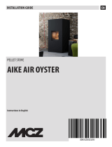
How is the pellet cooker made
1Flue clamp
2Pellet hopper lid
3Ceramic-glass cooktop
4Vermiculite
5Grate
6Spark plug
7Ash drawer
General information
What are wood pellets?
Wood pellet is a fuel which consists of pressed wood sawdust, often obtained from scraps of carpentry. The material used cannot contain
any foreign substances such as glue, lacquer or synthetic substances.
The wood is dried and cleaned and then pressed using a perforated matrix: due to the high pressure the sawdust heats to activate the
natural binders in the wood; in this way, the pellet maintains its shape, also without adding artificial substances. The density of the wood
pellets varies based on the type of wood and it can exceed 1.5 - 2 times that of natural wood.
The cylindrical sticks have a diameter of 6mm and a variable width between 10 and 40 mm.
Their density is equal to approx. 650 kg/m3 . Due to the low water content (< 10%) they feature a high energy content.
UNI EN ISO 17225-2:2014 (replacing EN PLUS) defines the quality of pellets by defining three classes: A1, A2 and B.
Length
Diameter
Bulk density
Heat power
Residual humidity
Ash
Specific weight
: < 40 mm
: about 6 mm
: ≥ 600 kg/m³
: ≥ 16.5 MJ/kg (4.6 kWh/kg)
: < 10 %
: <1.2 %
: >1000 kg/m³
Pellets must be transported and stored in dry places. On contact with humidity they swell, therefore making them unusable: therefore it is
necessary to protect them from humidity both during transport and storage.
Keep the fuel and other flammable materials at an adequate distance.
Ravelli recommends using wood pellets certified class A1 and A2 according to EN ISO 17225-2:2014 (EN PLUS), or standard
DIN PLUS (more restrictive than the class A1) or STANDARD M 7135.
The pellets can be light or dark, usually packed in bags bearing the manufacturer's name,
the main features and the classification according to the standards.
8Oven
9Combustion chamber door
10 Storage box
11 Vermiculite
12 Hopper
13 Smoke extractor
14 Combustion air inlet pipe
7
6
5
4
3
2
1
12
11
10
9
8
13
14

User manual MIA 90
Page8
Rev.2 03/02/2021
Combustion
Combustion is a chemical reaction in which two reactants, called fuel and oxidizer, combine generating thermal energy (heat) and producing
new substances (fumes).
To understand the expression described above, we consider this practical scheme named "combustion triangle"; it consists of three
elements that are necessary to have the combustion reaction. These three elements are:
• fuel (pellets)
• oxidizing agent (oxygen in air)
• trigger (Heat)
The reaction between the fuel and the oxidizing agent is not spontaneous, but occurs using an external trigger that is a heat source, flame
or spark. The trigger represents the ignition energy necessary for the reagent molecules to start the reaction. With the cooker off, this
energy must be supplied from an external source (Electrical ignition coil). Then, the energy released by the reaction makes selfsustainment
possible (brazier and high temperature in the combustion chamber).
The fuel and the oxidizing agent must be in adequate proportions because combustion is restricted to the so-called “inflammability field”.
Three types of combustion are reported below, the correct one is reported in Figure 3:
INCORRECT combustion, flame too drawn, in “blowtorch” style with a high quality of
incandescent pellets coming out of the brazier. Correct the pellet/air set by reducing the
percentage of air (from 0 to -5); if not sufficient, also increase the percentage of falling
pellets (from 0 to +5) to arrive to the condition in Figure 3.
If the changes made to the settings do not bring the stove to the right combustion conditions
in Figure 3, contact the Technical Support Centre.
INCORRECT combustion, “spring” flame in “wood stove” style with high quantity of pellets
not burning on the brazier. Firstly, check the door is closed and the ash pan. Secondly,
correct the pellet/air set by increasing the percentage of air (from 0 to +5); if not sufficient,
also reduce the percentage of falling pellets (from 0 to -5) to arrive to the condition in Figure
3.
If the changes made to the settings do not bring the stove to the right combustion conditions
in Figure 3, contact the Technical Support Centre.
CORRECT combustion, lively yellow/white flame with a minimum quantity of pellets on the
brazier.
Ideal combustion which does not require changes.
Figure 3 shows a flame produced by a stove with operating power set to maximum value.
Fig. 1
Fig. 2
Fig. 3
OXYGEN
HEAT
FUEL
Safety devices
The cooker is equipped with sophisticated safety systems, which avoid damage to the cooker and/or the home in the event of breakage
of a single piece or faults on the flue. In any case, if an anomaly occurs, the pellets are immediately stopped from falling and the switch
off phase activates.
The corresponding alarm is shown on the display. It is possible to see the details in the chapter dedicated to alarms.
Regulations, directives and Technical standards
All Aico SpA products are manufactured according to the regu-
lation:
• 305/2011 manufacturing materials
according to the guidelines:
• 2014/30 UE Electromagnetic Compatibility (EMC)
• 2014/35 UE Low voltage electric safety (LVD)
• 2011/65 UE RoHS 2
• 2014/53 UE Radio
And according to the standards:
• EN 14785
• EN 50165 • EN 62233
• EN 60335-1 • EN 60335-2-102
• EN 61000-3-2 • EN 61000-3-3
• EN 55014-1 • EN 55014-2
• ETSI EN 300220-1

User manual MIA 90
Page9
Rev.2 03/02/2021
COOKER INSTALLATION
Advice for installation
Because of the frequent accidents caused by the malfunctioning of the ues in residential buildings, this chapter has been drafted in
collaboration with Assocosma (association of stove/sweepping technicians and specialists of the eld) in order to facilitate the installer
to install the stove and build a system able to evacuate fumes in accordance with the regulations in force.
-Regulation 305/2011 concerning manufacturing products for CE marking (CPR);
-UNI 10683:2012 for installing a heat generator to solid biofuels (wood, pellets or other biomass);
-UNI/TS 11278:2008 regarding the choice of metallic fumes exhaust system components;
-UNI 10847:2000 concerning maintenance and control of fume systems for heat generators with liquid or solid fuel;
-UNI EN 13384-1:2008 regarding thermal and uid-dynamic calculation methods for chimneys;
- UNI/EN 1443:2005 regarding the installation with the minimum essential chimney requirements met (followed by the compilation of
fume dataplate to be afxed to the same).
- UNI EN 15287-1:2010 and UNI EN 15287-2:2008 for the design and installation of chimney systems, for the construction of
chimneys installed on site and the existing chimney piping (part 1) and the design, installation and labelling of chimney systems, ues
and air intake ducts for watertight heating appliances (part 2).
Excerpt from standard UNI 10683:2012
Approved and non approved installations
In the case of installation in places where there aret more appliances powered with different fuels, as well as with or without extractor
hoods, during preventive inspections and during ignition test you must assess the situation in order to detect any deviations from the
design conditions or other aspects not obvious upon design phase.
The room must have adequate ventilation according to the manufacturer's instructions for each individual appliance.
Ventilation must be calculated to ensure the functioning of the devices at the same time and in the most severe operating conditions.
IT is prohibited to install equipment which is not watertight in premises for residential purposes:
- in which there are liquid fuel-operated appliances with continuous or intermittent operation, which draw the combustion air in the
room in which they are installed;
- in which there are type B gas appliances intended for room heating, with or without production of domestic hot water and in adjacent
and adjoining premises;
- in which, in any case, the depressurization measured during installation between the internal and external environment is greater
than 4 Pa (see Appendix F of the UNI 10683 for more details).
The installation of watertight equipment can be carried out without limitations.
Installation in bathrooms, bedrooms and studio ats is only allowed for sealed or closed hearth appliances with ducted combustion
air taken from the outside.
Installation in premises with re hazards is forbidden.
Installation place requirements
System compatibility should be checked before assembly and installation.
The adjacent side and rear walls and the supporting surface must be made of non-combustible and heat-resistant material, unless
otherwise specied below.
Installation next to combustible materials or heat-sensitive materials is allowed provided that the minimum clearance recommended
is observed and suitable protection is provided with insulating and non-combustible materials. This should however be provided by
the manufacturer's instructions. When the installation instructions are not available, the installer will have to secure the appliance and
shall be liable for its commissioning.
Before installation you should check the position of the cooker, ue or exhaust terminals of the
following have been observed:
- Installation restrictions
- Limitations provided by local administrative regulations or specic provisions of the local bodies.
- Conventional limitations imposed by the residence regulations, easement or contracts.
After surveying the installation place, the installer should check the following:
- the type of appliance;
-The minimum volume of the installation place indicated by the manufacturer is however greater then 15 m3;
- the instructions of the manufacturer of the heat generator regarding the requirements of the fume exhaust system;
- the internal cross section of the fume duct, the composing materials, the evenness of the cross section, the absence of
obstructions;
- height and length on vertical plane of the chimney;
- the existence and compliance of chimney terminal;
- the possibility to t external air vents and the dimensions of existing vents.
The complete ue exhaust system must be supplied and installed in compliance with the regulations issued by the standardization
bodies and should be installed according to state-of-the-art standards.
Air inlet:
The installation place of non-watertight appliances must be sufciently ventilated with special vents that allow the circulation of air in
the room.
Air must be taken directly from the outside (not from other rooms, garage, ect) and must have a net usable section equal to or greater
than 80 cm2 for pellet stoves and heaters (EN 14785) and 100 cm2 for boilers (EN 303-5).
The vent grids must be positioned so that they cannot be blocked and to allow the withdrawal of clean air.
Verify and respect the ventilation requirements for simultaneous operation of multiple combustion appliances in the presence of
forced ventilation systems or hoods (refer to section 6.4 of the UNI 10683).
The air intake is not required when installing watertight appliances that take air directly from the outside.

User manual MIA 90
Page10
Rev.2 03/02/2021
Fume duct and ttings:
The term fume channels refers to the pipes that connect the appliance to the chimney.
For heat generating devices equipped with an electric fume exhaust fan you must follow the installation instructions of the manufacturer
regarding the maximum length and number of bends of the exhaust ducts.
In case the maximum values or those resulted from the preliminary calculation as per UNI EN 13384-1 are not available , you should
follow the provisions below:
The horizontal sections must have a minimum upward slope of 3%;
The length of the horizontal section should be minimum and its plan projection should not exceed 4 metres;
- the number of direction changes including one for the introduction into the chimney and excluding that for the effect of the use of the
"T" element in appliances with rear ue, must not exceed 3.
- direction changes should not have an angle greater than 90° (45° bents recommended);
- this section should have constant diameter and equal at re box outlet up to the tting into the ue;
- it is forbidden to use exible metal and cement bre tubes and pressurization should be ensured at all times;
- fume channels must not pass through rooms where the installation of combustion appliances is prohibited.
In any case, the fume ducts should be sealed and protected against combustion products or condenstae as well as insulated if
passing outside the installation room.
It is not allowed to mount manual draught adjustment devices on forced draught appliances.
Chimney:
-must be made of materials suitable to guarantee resistance to normal mechanical stress, chemical resistance and have
proper insulation to prevent the formation of condensate; it should, therefore, be thermally insulated;
- chimney product standard EN 1856-1 and used materials standard UNI/TS 11278).
- be predominantly vertical and have no narrowing along their entire length.
- be properly spaced by means of air gaps and insulated with non ammable materials.
- maximum direction changes should be 2 at angles below 45°.
- the ue installed inside the house should be insulated and can be inserted into a chimney terminal as long as the
piping standards are complied with;
-the fume duct should be connected to the chimney by means of a T tting with a collection chamber tted
with inspection glass to check the combustion residues and condensate collection.
The combustion products must be released above the roof. It is not possible to connect the appliance to a ue shared with other
combustion appliances or with exhausts of hoods.
Flue dataplate:
Supplied with the chimney, it identies:
- the manufacturer;
- the CE marking;
- the description of the product according to EN 1856-1 (metal ue) and EN 1856-2 (metal smoke channels)
There is also a part to be completed by the installer which certies the suitability of the chimney to the appliance installed, installation
standard EN 1443.
Example of designation EN 1443:
EN 1856-1 T400 N1 D 3 G 30
with b c d e f g
KEY:
to: Reference standard (in this case steel chimney)
b: Indicates the temperature class (T80, T200, etc.);
c: Indicates the protection class (N-->negative - P--> Positive - H-->High pressure; “x”--> indicates the loss allowed whereas 1 is
the most restrictive);
d: It indicates the condenstae resistance class (D-->for dry use - W-->for wet use);
e: Indicates the corrosion resistance class (1, 2, 3 or m);
f: Indicates the soot re resistance class (G--> soot re resistant O--> not soot re resistant);
g: Indicates the distance to keep from combustible materials.
1) DESIGNATION EN 1443: T400 N1 D 3 G(30)
2) DIAMETER: 100 mm
3) DISTANCE FROM FLAMMABLE MATERIAL: 30 mm
4) INSTALLER (name/address):
Mario Bianchi Via Rossi 24 Calcinate (BG)
5) DATE: 01/27/2014
.......................................................................................................................
WARNING: THIS LABEL SHOULD NOT BE REMOVED OR MODIFIED
Last two digits
of the year in which the
marking has been afxed
Identication
number
Certicate number
Designation
stated by
manufacturer
Section compiled
by the installer
NAME and BRAND
MANUFACTURER
CERTIFICATE CE:01234-CPD-0999
Chimney System: EN 1856-1 T400 N1 D v3 l50050 G(30)
SECTION RESERVED TO THE INSTALLER
xx
01234

User manual MIA 90
Page11
Rev.2 03/02/2021
Chimney cap:
The UNI 10683 prescribes that the chimney cap must meet the following characteristics:
- The ue section must be at least twice the inner section of the chimney;
- Have a structure suitable to prevent water or snow from entering;
- Be built so that in the presence of wind it still ensures fume exhaust
(wind-proof chimney cap)
- the release height measured between the lower covering layer and the
lower point of the fume release into environment must be outside of the
reux area;
- Be built at safe distance from antennas or parabolic antennas
never be used as a support;
Safe distances for proper installation of chimney terminal:
Reux area
IT IS MANDATORY TO HAVE THE EXHAUST THROUGH THE ROOF IT IS FORBIDDEN TO DISCHARGE FLUES THROUGH A DIRECT
SYSTEM OR ANY OTHER SYSTEM NON COMPLIANT TO REGULATIONS
The exhaust height must be outside the reux area calculated according to the gure and the table given above.
Next to the ridge it should be considered the smaller among the two.
Position in relation to other chimneys
If you need to install the chimney near another existing chimney for fume evacuation, it is necessary to respect the distances shown in the table.
Placement in relation to skylights and dormers
The outlet of the chimney cap must be located outside of the clearance zones indicated in the gure.

User manual MIA 90
Page12
Rev.2 03/02/2021
Testing and commissioning
Commissioning must be preceded by a test that involves the verication of the operation of the following elements:
- the suitability of the fumes exhaust system;
- connection to external air vents, if any;
- electric and hydraulic connections;
- check that all the materials that make up the smoke duct, ue, chimney terminal are suitable for use and compliant with standards
(fume exhaust of a stove with solid fuel).
For heat generating devices powered by mechanical systems testing must be done according to manufacturer's instructions.
The test is considered successfull when all operation phases are completed without encountering anomalies faults.
Additional documentation and informations for the user
Upon installation completion, the installer should hand over to the user:
- the user's manual of the appliance supplied by the manufacturer;
- the technical documentation of the accessories used and subject to maintenance;
- the documentation of the ue exhaust system;
-The system booklet (where applicable);
- the documentation that certies installation completion;
The documentation required to cover installer's liability comprises:
- detailed description (including photos) of other heat generators present;
- declaration of conformity of the state-of-the-art system (D.M. 37/08);
- description of overall dimentions, layout or photos regarding the modications brought to the layout in case it was necessary
to intervene during installation;
The use of certied material with CE marking (305/2011);
- any information regarding the warranty;
- the date and singature of installer;
Outlet height in the presence of a technical volume or obstacle with openings and windows
Outlet height in the presence of a technical volume or obstacle without openings
The symbol Z indicates the height (mm) from
the obstacle or the technical compartment
Roof with slope β ≤ 10° Roof with slope β > 10°
Distance
(mm)
Outlet height Distance
(mm)
Outlet height
X ≤ 2000 Z + A2X ≤ 3000 Z + A2
X > 2000 B X > 3000 B
The symbol Z indicates the height (mm) from the obstacle or the technical
compartment.
* If the terrace or at roof is walkable, you should observe the relative distanc-
es from the oor recommended for roof with slope β ≤ 10°.

User manual MIA 90
Page13
Rev.2 03/02/2021
Maintenance schedule.
Maintenance should be carried out periodically as shown in the table below, and in the manner prescribed by standards and performed
by qualied personnel; upon completion a regular intervention report should be issued.
The installer should ask for the receipt of delivered documentation and preserve it together with the technical
documentation regarding the installation performed.
REFERENCE KEY OF SYSTEM DECLARATION OF CONFORMITY
1. Like in the case of gas plants, by "other" we may mean the replacement of a device installed in a xed manner.
2. Specify: name, surname, qualication and (when there is an obligation as per Art.5, paragraph 2) registration data to the relative
Professional association of the technician that drafted the project.
3. Specify the technical standards and regulations in force, classifying them per design, execution and inspection.
4. Should the system executed according to the design be modied during work, the project submitted at the end of the works should
include the versions made. The project also includes the re prevention protocol (where applicable).
5. For products subject to standards, the report should contain a complete statement of compliance to the same, where applicable,
with reference to marking, test certicates etc. issued by authorized bodies.
For the other products (to be listed) the signatory should declare that it regards materials, products and parts compliant with
provided for in articles 5 and 6. The report should state the compliance with installation area.
When this is relevant for the proper operation of the system, indications on the number or features of appliances installed or
about to be installed should be provided (e.g. for gas: 1) number, type and power of appliances; 2) features of the parts
that make up the ventilation systems of the area; 3) features of the system that feeds the fuels;
4) information on appliance wiring, where applicable).
6. The layout of the system executed includes the description of the works done (with simple reference to the project when the latter
was drawn up by an authroized professional and variations during works have not been approved). In the case of:
modication, enlargement and non-routine maintenance, the intervention should be integrated, if possible, into the layout of
the existing system. The layout shall include the re prevention protocol (where applicable).
7. The reference data include the name of the company that carried out the works and the date of the statement. For plants or parts
of plants built before the entry into force of this decree, the reference to declarations of conformity may be replaced by a reference
to declarations of conformity (Article 7, paragraph 6). If part of the system is executed by another company (such as ventilation and
fume exhaust in gas installations), the declaration should include reference data for the said parts.
8. If the installation includes products or systems legitimately used for the same job in another Member State of the European Union
or party to the Agreement on the European Economic Area, for which there are no
technical standards for the product and installation, the declaration of conformity should be annexed to the project drafted and
signed by a registered professional engineer in accordance with the specic technical skills required, certifying that the risk assessment
associated with the use of the product or production system was performed, and the fact that he had adopted all necessary measures
to achieve levels of safety equivalent to those guaranteed for the installations carried out, according to sate-of-the-art standards and
to have supervised the proper execution of the installation in all its phases in compliance with all technical
standards provided by the manufacturer of the system or the product.
9. Example: any certicates containing the outcome of the checks performed on the system before commissioning or cleaning,
sanitizing treatments etc..
10. Upon completion of works, the company that installed the system should issue the client a declaration of conformity of the
systems in compliance with the standards in Art.7. The client or the owner should entrust installation, modication, enlargement and
maintenance tasks of the system in Art. 1 exclusively to authorized companies as per Art. 3.
Type of appliance installed <15 kW (15 - 35) kW
Pellet-fueled appliance 2 years 1 year
Appliances with open rebox 4 years 4 years
Appliances with close rebox 2 years 2 years
Water appliances 1 year 1 year
Boilers 1 year 1 year
Fume exhaust system 4 t of fuel 4 t of fuel

User manual MIA 90
Page14
Rev.2 03/02/2021
DECLARATION OF CONFORMITY OF THE STATE-OF-THE-ART SYSTEM
In accordance with. art. 7 of MD 37 dated January 22, 2008 n. 20
The undersigned ___________________________________ owner or legal representative of the company ___________ (company's
name)___________
operating in the crafts sector based in _ _ _ _ _ _ _ _ _ _ _ _ _ _ _ _ _ _ _ _ _ _ _ _ _ _ _ _ _ _ _ _ _ _ _ _ _ _ Municipality _ _ _ _ _ _ _ _ _ _ _ _ _
_ _ _ _ _ _ _ _ _ _ _ _ _ _ prov. (___) ph. _ _ _ _ _ _ _ _ _ _ _ _ _ _ _ _ _ _ _ _ _ _ _ _ _ _ _ _ _ _ _ VAT _ _ _ _ _ _ _ _ _ _ _ _ _ _ _ _ _ _ _ _ _ _ _
_ _ _ _ _ _ _ _ _ _ _ _ _ _ _ _ □ entered in the register of companies (DPR 7/12/95 n.581 della CCIAA di TV n. xxx
□ registered at the Register of Provincial Handicraft Manufacturers (L. 8.8.1985, n.443) di TV n. xx
installation executed by (schematical description, project layout):_________________________________________________
______________________________________________________________________________________________
______________________________________________________________________________________________
______________________________________________________________________________________________
intended as: □ new system □ makeover □ upgrade
□non-routine maintenance □ other(1) ................................................................
Commissioned by__________________________________ installed at the premises in the Municipality of ____________________________
Prov.
street_____________________________________ oor ____internal, owned by ________(name, surname or company's name and ad-
dress)______
in the building designated as: □ industrial □ civil □ trade □ other uses
DECLARES
under its sole responsibility that the machine was built in compliance with state-of-the-art standards
in accordance with the provisions of Article 6, taking into account the operating conditions and the designated uses of the building, having in particular:
□ observed the project drafted as per Art.5 by(2) .........................................................................................................................
□ followed the technical standard specic to its use as(3) UNI10683/2012 UNI10845 UNI/TS11278 UNI/EN1443 UNI7129/08
□ installed parts and materials suitable for the place of installation (Art.5 and 6)
□ inspected the system for safety purposes and the functionality with positive outcome, having carried out the checks
required by the standards and the provisions of the law.
Mandatory annexes:
□ project as per Articles 5 or 7(4)
□ report with the types of materials used(5)
□ layout of the system made(6)
□ reference to previous or partial declarations of conformity, already existing(7):
executed by the company ............................................................................. date ...........
□ copy of the certicate of acknowledgement of technical and professional requirements
□ certicate of conformity for the system executed with non-standard materials or systems(8).
Optional annexes: Photographic Documentation. Use and maintenance manual of the replace, the Fume dataplate and booklet of the generator,
declaration of insulation compliance, combustion analysis, draught test, local ventilation and CO verication and chimney seal test
DENIES
all liability for injuries or damages to property arising from tampering with the system, by third party or due to lack of maintenance or repair(9) .
Date ___________________ The technical manager __________________________ The undersigned ____________________________
WARNING FOR THE BUYER: liability of the buyer or the owner,art.8(10)
The undersigned _________________________________________ buyer of the works/owner of the building declares to have received _____
copies of this document and the specied annexes.
Date _______________________ Signature __________________

User manual MIA 90
Page15
Rev.2 03/02/2021
This type of installation (See Figure 1) requires the chimney to
be insulated despite the fact that the entire duct is
installed inside the building. Moreover, the structure should be
inserted into a properly
ventilated skylight well.
At the bottom of the chimney is provided an inspection cover
suitably isolated from wind and rain.
It is not recommended to install a 90° curve as the rst section,
since the ash could quickly obstruct the smoke passage,
compromising the draught. (See Fig. 2)
This type of installation (See Fig. 3) does not
require insulated ue for the section
inside the building, while the section located outside of the
building should be made of insulated tubes. The lower part
of the ue has an assembled “T” joint with an inspection
plug.
In this way you can inspect the outer section.
Examples of installation of a pellet cooker
IT IS MANDATORY TO USE WATERTIGHT PIPES WITH SILICONE SEALS.
Protection contre la pluie
Im.1
Grille pour passage de l'air dans
le vide technique avec ouverture
pour inspection du carneau
Vide
technique
Raccord en T pour condensation
Carneau calorifugé
Canal pour fumée :
utilisation de tube
non calorifugé
Raccord en T
Carneau calorifugé
Fig.3
Protection contre la pluie
Chambre de collecte des
cendres de combustion
+ bouchon de
condensation
Fig.2
Cenere depositata nella
curva a 90°
NO

User manual MIA 90
Page16
Rev.2 03/02/2021
In case you need a horizontal section to attach to an existing
chimney (see Fig. 5), respect the gradients shown in the
gure, so as to reduce the ash storage in the horizontal pipe.
In the lower part of the ue duct was installed a T tting with
inspection plug like for the ue inlet.
Fig.5
This type of installation (see Figure 4) requires insulated
chimney since the entire smoke duct was assembled inside
the house.
The lower part of the ue has an assembled “T” joint with an
inspection plug.
Fig.4
Protezione dalla pioggia
Canna fumaria coibentata
Raccordo a T con
scarico condensa e
camera di raccolta
Inclinaison > 3 %
Max 3 m et 4 courbes
Fig.5
Raccord en T
Trappe d'inspection
Protection contre la
pluie

User manual MIA 90
Page17
Rev.2 03/02/2021
The data reported above are indicative and not binding. They can vary based on the type of pellets used. Ravelli reserves the right
to make changes to enhance the performance of its products
TECHNICAL CHARACTERISTICS
UdM
Height mm 850
Width mm 900
Depth mm 600
Oven dimensions (hxwxd) mm 345 x 359 x 415
Empty weight Kg. 232
Diameter of smoke release tube mm 80
Max heating volume m3185
Input Red. - Rat. kW 3.0 - 10.6
Output power Red. - Rat. kW 2.7 - 9.3
Hourly pellet consumption Red. - Rat. kg/h 0.62 - 2.2
Power consumption upon switch-on W 270
Power consumption at rated power W 28
Power consumption at reduced power W 13
Power consumption in stand-by W 2,2
Additional electric power of electric grill W 1132
Additional electrical power of oven bulb W 40
Electrical power supply V - Hz 230 - 50
Tank capacity Kg. 19
Autonomy min - max h 9 - 30
Efciency Red. - Rat. %89.02 - 87.0489.02 - 87.04
CO at 13%O2 Red. - Rat. % 0.029 - 0.004
Fumes ow rate Red. - Rat. g/s 4.02 - 6.70
Minimum suction 0.1 mbar - 10 Pa
Fume temperature Red. - Rat. °C 104 - 218
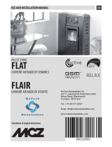
The Coocker Mia 90 is not suitable for recessed installation.
To ensure adequate ventilation, a space of 50 mm must be maintained between the stove and the rear and side walls, even if the
walls are not combustible.
R = right side 150 mm
L = left side 150 mm
B = back side 100 mm
S = upper side 800 mm
A = front side 1000 mm
850
900
486
152
80
600
194
294
50
Mod.
DESCRIZIONE
Data
Dis.
Appr.
MODIFICHE
CP01-00-001A
MOD.
A3
(SCHEET)
FORMATO
255.853
TOLLERANZE GENERALI PER QUOTE LINEARI, ANGOLARI, SMUSSI E
RACCORDI, CLASSE FINE UNI EN 22768-1, DOVE NON INDICATE
1:10
giovedì 28 gennaio 2016
SCALA
(SCALE
)
DENOMINAZIONE
(DENOMINATION
)
MATRICE
will be legally pursued.
diritti a rigore di legge.
and must not be released to other parties without written consent any infringement
in any way utilized for the manifacture of the component of unit herein illustrated
All proprietary right reserved by Society Ravelli Group This drawing shall not be reproduced or
ne venire comunicato a terzi o riprodotto. La Societa' proprietaria tutela i propri
disegno non potra' essere comunque utilizzato per la costruzione dell' oggetto rappresentato
Proprieta' della Societa' Ravelli Group Senza autorizzazione scitta della stessa, il presente
MODIFICARE SOLO SU CAD
(CHECKED)
CONTR.
(WEIGHT)
PESO Kg
DIS.
MATERIALE
(MATERIAL)
(DESIGNER)
DATA
(DRWG NR.)
N. DISEGNO
(DATE)
CAD DRAWNING HANDLING ON CAD SYSTEM ONLY
TRATTAM. SUPERFICIALE
Posizione file di disegno:
Posizione modello 3D:
X:\ECO-PROGETTI\00_STUFE\ARCHIVIO-VALIDI\MODELLI-SW-1\CUCINE A PELLET\CP01-90_Cam_Comb_SX\
Ultimo salvataggio di:
mtengatini -
Data ultimo salvataggio:
giovedì 28 gennaio 2016 17:48:06
A.Odori
-
CUCINA PELLET
Via Kupfer 25036 Palazzolo S/O - BRESCIA - ITALY

User manual MIA 90
Page18
Rev.2 03/02/2021
MIA 90 pellet cooker specications
Ravelli cooker Mia 90 is a product of the latest generation combining tradition of wood cookers with technology, comfort and quietness of
modern pellet stoves.
It has been designed to ensure the heating of homes and, simultaneously, to be used as a cooker. In fact, you can cook either on the cooktop
in ceramic glass or in the oven, heated directly by ame and hot fumes.
How to use the cooktop
The cooktop is divided into different heating zones.
For fast cooking and high temperature you can use the cast iron oven (MAX) placed directly over the ame.
MED and MIN positions are useful for slow cooking and keeping food warm.
How to use the oven
The cooker is fully equipped for cooking food. The oven temperature can be set between 120°C and 250°C.
The automatic control system of combustion “Ravelli Cooking System” ensures that the set temperature is reached and maintained for the desired
cooking time. During cooking, you can activate the electric grill, useful to keep food warm at the end of the cooking process.
Due to the thermal inertia, oven cooling may be much slower than the heating. In the rst periods of use of the cooker, it is advisable to check the time
required to reach the temperature in cooling mode. To speed up the oven cooling process, you can open the oven’s door for a few seconds.
YOU can also use the oven in the summer to warm food, by activating the electric grill.
To use the oven and the electric grill you need to use the cooker in COOKING MODE. All the relevant information
is given in the following sections.
MAX oven
MIN Position
MED Position
THE TIME NEEDED TO REACH THE TEMPERATURE OF THE OVEN AND THE ACTUAL MAXIMUM AND MINIMUM
TEMPERATURE WITHIN THE OVEN DEPENDS ON THE TYPE AND QUALITY OF PELLETS USED.
PLACE THE COOKWARE AND KITCHEN UTENSILS CAREFULLY ON THE GLASS-CERAMIC COOKTOP.
BE CAREFUL NOT TO DROP WATER ON LIVE PARTS.
How to unpack the cooker
First open the package; if possible, remove the cooker from the package near the area where it will be installed. The materials that make up the packing
are neither toxic or harmful, therefore do not require special disposal procedures. Further storage, disposal or possible recycling is the responsibility
of the end user, as per the existing laws.
The device must be installed so as to provide easy access for cleaning the oven and the gas and fume exhaust ducts.
You should pay particular attention to the door and its glass, as well as the cooktop, that must be protected from shocks that
compromise their intact state.
IMPORTANT INFORMATION FOR CORRECT DISPOSAL OF THE PRODUCT
Demolition and disposal of the product is the sole responsibility and liability of the owner who must comply with the laws in force in
his country regarding safety, respect for and protection of the environment.
At the end of its service life, the product must not be disposed of as municipal waste. It must be taken to a special local authority
differential waste collection centre or to a dealer providing this service.
Disposing of electrical equipment separately you avoid negative consequences for the environment and for health deriving from
its incorrect disposal, plus it allows you to recycle constructional materials, which contributes in important savings in energy and
resources.
To obtain the best results from your cooktop we recommend you use the cooker in HEATINGmode at
full power.
Getting started

User manual MIA 90
Page19
Rev.2 03/02/2021
How to remove the xing plates
The cooker is secured to the pallet with special plates, to prevent damage during transport.
To remove the plates it is necessary to remove the side panels.
Loosen the xing screws of the side panels, on the back of the cooker.
Loosen the xing screws of the plates on the wooden pallet.
Remove the side panels.
850
900
486
152
80
600
194
294
50
Mod.
DESCRIZIONE
Data
Dis.
Appr.
MODIFICHE
CP01-00-001A
MOD.
A3
(SCHEET)
FORMATO
255.853
TOLLERANZE GENERALI PER QUOTE LINEARI, ANGOLARI, SMUSSI E
RACCORDI, CLASSE FINE UNI EN 22768-1, DOVE NON INDICATE
1:10
giovedì 28 gennaio 2016
SCALA
(SCALE
)
DENOMINAZIONE
(DENOMINATION
)
MATRICE
will be legally pursued.
diritti a rigore di legge.
and must not be released to other parties without written consent any infringement
in any way utilized for the manifacture of the component of unit herein illustrated
All proprietary right reserved by Society Ravelli Group This drawing shall not be reproduced or
ne venire comunicato a terzi o riprodotto. La Societa' proprietaria tutela i propri
disegno non potra' essere comunque utilizzato per la costruzione dell' oggetto rappresentato
Proprieta' della Societa' Ravelli Group Senza autorizzazione scitta della stessa, il presente
MODIFICARE SOLO SU CAD
(CHECKED)
CONTR.
(WEIGHT)
PESO Kg
DIS.
MATERIALE
(MATERIAL)
(DESIGNER)
DATA
(DRWG NR.)
N. DISEGNO
(DATE)
CAD DRAWNING HANDLING ON CAD SYSTEM ONLY
TRATTAM. SUPERFICIALE
Posizione file di disegno:
Posizione modello 3D:
X:\ECO-PROGETTI\00_STUFE\ARCHIVIO-VALIDI\MODELLI-SW-1\CUCINE A PELLET\CP01-90_Cam_Comb_SX\
Ultimo salvataggio di:
mtengatini -
Data ultimo salvataggio:
giovedì 28 gennaio 2016 17:48:06
A.Odori
-
CUCINA PELLET
Via Kupfer 25036 Palazzolo S/O - BRESCIA - ITALY
x2 x2
x6
1
2

User manual MIA 90
Page20
Rev.2 03/02/2021
Wiring
The power cord of the appliance should only be connected
after the end of the installation and assembly of the
equipment and must remain accessible after installation.
Make sure that the power cord (and any other external
cables to the unit) does not touch the hot parts.
If the power supply cable is damaged, it must be replaced
by the manufacturer or its after-sales service or by a
similarly qualied person, so as to avoid all risks.
The I/O switch in the gure should be set to I to power the
cooker. If there is no voltage, check the state of the fuse
installed next to the switch (4A fuse). During the periods
of inactivity, we recommend you disconnect the power
cord of the cooker.
What to check before turning on the cooker
Make sure you have removed all parts that pose the risk of burns from the combustion chamber or glass (various instructions or
stickers).
Before turning on the appliance, make sure you have tted the brazier on the support base and check that the door and the ash
pan are properly close.
Fuel supply consists in the insertion of pellets from the top of the cooker, by opening the door. During pellet loading prevent the
pellet bag from coming into contact with hot surfaces (i.e. the cooktop).
How to load the pellets
NEVER INSERT INTO THE TANK OTHER KIND OF FUEL OTHER FROM THE PELLETS
COMPLYING WITH THE SPECIFICATIONS BELOW
I/O switch
Fuse
Pellet door
Hopper
If the user opens the door or the ash pan during cooker operatio, the load of pellets in the brazier is
interrupted. Every 5 seconds, a sound signal followed by the appearance of a warning on the screen of
your handheld (to the left) warns the user; to resume the regular operation, the doors must be closed. If
the safety devices are not restored within one minute, the cooker goes in alarm condition (Alarm 07). In
this case, reset the alarm and switch on the cooker again.
/