Page is loading ...

7283659 (Rev. D 8/20/07)
Product No. 8562921--A
Model WHES20
Model WHES30
How to install, operate and
maintain your Demand
Controlled Water Softener
If you have questions or concerns when
installing, operating or maintaining your
softener, call our toll free number:
1--866--986--3223
Monday -- Friday, 8 am -- 9 pm EST
Do not return water softener to store
System Tested and Certified by
NSF International against NSF/ANSI Standard 44
forsoftenerperformance.

2
Tab l e o f Co n te n t s
Water Softener Safety 3..........................................................................
Before You Start 3...............................................................................
Inspect Shipment 4..............................................................................
Water Softener Dimensions 5.....................................................................
Water Conditioning Information 6..................................................................
Water Conditioning 6.........................................................................
How A Water Softener Works 6....................................................................
Softening Cycle 6............................................................................
Regeneration Cycle 6.........................................................................
Installation Requirements 8.......................................................................
Tools and Parts Needed 8.....................................................................
Location Requirements 9......................................................................
Air Gap Requirements 9......................................................................
V alve Drain Requirements 10...................................................................
Planning Installation 11............................................................................
Inlet --- Outlet Plumbing Options 11..............................................................
Installation 12....................................................................................
Turn Off Water Supply 12.......................................................................
Install Brine Tank Overflow Elbow 12.............................................................
Move the Water Softener into Place 13...........................................................
Assemble Inlet and Outlet Plumbing 14..........................................................
Connect Inlet and Outlet Plumbing 14...........................................................
Install Valve Drain Hose 15.....................................................................
Install Salt Storage Tank Overflow Hose 15.......................................................
Tes t for Leak s 15..............................................................................
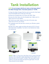
AddWaterandSalttotheSaltStorageTank ...................................................
NO T AG
Sanitize the Softener/Sanitize After Service 16....................................................
Plug in Water Softener 16......................................................................
Program the Water Softener --- Model WHES20 17....................................................
Set Time of Day 17............................................................................
Set Water Hardness Number 18.................................................................
Set Recharge (Regeneration) Time 18...........................................................
Start a Recharge 18...........................................................................
Program the Water Softener --- Model WHES30 19....................................................
Set Time of Day 19............................................................................
Set Water Hardness Number 20.................................................................
Set Recharge (Regeneration) Time 20...........................................................
Start a Recharge 20
...........................................................................
Customizing Features / Options---Model WHES20 21..................................................
Recharge 21..................................................................................
Recharge Tonight 21...........................................................................
‘‘Power---Outage Memory’’ 21..................................................................
Salt Efficiency 22..............................................................................
Customizing Features / Options---Model WHES30 23..................................................
Recharge 23..................................................................................
Recharge Scheduled / Tonight 23...............................................................
SetSaltLevel 23..............................................................................
Electronic Control / ‘‘Power---Outage Memory’’ 24.................................................
Water Flow Indicator 24........................................................................
Salt Efficiency 24..............................................................................
Clean / Clear Water Iron Removal 25............................................................
Clean Feature Minutes 25......................................................................
Maximum Days Between Regenerations 26.......................................................
12 or 24 Hour Clock 26........................................................................
Routine Maintenance 27...........................................................................
Refilling With Salt 27...........................................................................
Breaking A Salt Bridge 27......................................................................
Cleaning the Nozzle and Venturi 28..............................................................

3
Troubleshooting Guide 29.........................................................................
Automatic Electronic Diagnostics 30.............................................................
Manual Advance Diagnostics---Model WHES20 30.................................................
Manual Advance Regeneration Check---Model WHES20 31.........................................
Manual Advance Diagnostics---Model WHES30 32.................................................
Manual Advance Regeneration Check---Model WHES30 33.........................................
Wiring Schematic 35..............................................................................
Warranty 35......................................................................................
Softener Components 36..........................................................................
Water Softener Safety
For installations in the Commonwealth of Massachusetts:
Installation by a licensed plumber is required. Plumbing code 248--CMR of the Commonwealth
of Massachusetts must be used for installation.
For installations in the state of California:
You must turn the Salt Efficiency Feature setting to ON. This may initiate more frequent re-
charges, however, it will operate at 4,000 grains per pound of salt or higher. To turn on the Salt
Efficiency Feature, follow the instructions in the “Salt Efficiency” section of this manual.
Before You Start
See “Location Requirements” section before installing water softener.
Follow the installation instructions carefully. (Failure to install the water softener properly voids the
warranty.)
Before you begin installation, read this entire manual. Then, obtain all the materials and tools you will
need to make the installation.
Check local plumbing and electrical codes.
Use only lead--free solder and f lux for all swe at-solder connections, as required by federal codes.
Use care when handling the water softener. Do not turn upside down, drop, or set on sharp protrusions.
Avoid installing in direct sunlight. Excessive sun heat may cause distortion or other damage to
non--metallic parts.

4
The water softener requires a minimum water flow of 3 gallons per minute at the inlet. Maximum
allowable inlet water pressure is 125 psi. If daytime pressure is over 80 psi, nighttime pressure may
exceed the maximum. Use a pressure reducing valve if necessary. (Adding a pressure reducing valve
may re duce the flow.) If your home is equipped with a back flow pr eventer, an expansion tank must
be installed in accordance with local codes and laws.
The water softener works on 24 volt--60 hz electrical power only, supplied by a direct plug--in
transf ormer (included). Be sure to use the include d transformer and plug it into a nominal 120V, 60
cycle household outlet that is proper ly protected by a n overcur rent device such as a circuit bre aker or
fuse. If transformer is replaced, use only the authorized service, Class II, 24V 10VA transformer.
This system is not intended to be use d for tre ating water tha t is micr obiologically unsafe or of unknown
quality without adequate disinfection before or after the system.
Europea n Directive 2002/96/E C requires al l electric al and electronic equipment to be disposed of
according to Waste Electri cal and Electronic Equipment (WEEE) requirements. This directive or
similar l aws are i n place nationally and can vary from re gion t o region. Please refer t o your state
and loca l laws for proper disposal of this e quipment.
Inspect Shipment
The parts required to assemble and install the water softener are included with the water softener.
Ground cla mp Single va lve bypass 20 ft. drain hose
Hose adaptor Hose clamps Installation adaptors
Clips O--rings Grommet
Water hardness test strip
Thoroughly check the water softener for possible shipping damage and parts loss. Also inspect and
note any dama ge to the shipping carton.
Remove and discard (or recycle) all packing materials. To avoid loss of small parts, we suggest you
keep the small parts in the parts bag until you are ready to use them.
Do not return the water softener to store.
If you have any questions, or there are missing parts or damage, pl ease call
1---866---986---3223, Monday --- Friday, 8 am --- 9 pm EST.
Before you call please have your model number, date of purchase, water
conditions and number of people living in your home.

5
For future reference, enter the following information.
Model No. no
Code n
*Water hardness gpg
Serial No. no
Installation date
**Iron content ppm
n on registration decal (located under salt hole cover) o on shipping carton
* A hardness test strip is provided with your water softener.
** Kits are available at retail hardware stores for testing water hardness and iron content. Some retail
stores will also test your water for a fee.
Water Softener D imensions
IN
OUT
3---3/8”
B
C
A
I N --- O U T
18”
19”
MODEL NOMINAL RESIN TANK SIZE A B C
WHES20 8” DIA. X 35” 36---1/2” 35” 43---5/16”
WHES30 9” DIA. X 35” 36---1/2” 35” 43---5/16”

6
How a Water Softener Works
Softening Cycle
When the water softener is providing soft water, it is called “service” or the “ softening cycle”. During
this cy cle, har d water flows from the main water pipe in the household into the water sof tener. Inside
the resin ta nk is a bed made up of thousa nds of tiny, plastic resin beads. As hard water passes through
the bed, each bead attracts and holds the hardness minerals. Water without the hardness minerals (soft
water) flows from the water softener to the rest of the house .
Regeneration Cycle
Eventually the beads become coated with calcium or magne sium ions. At this point, the water softener
needs to replenish the beads with sodium ions. This process is called “regeneration”.
Regeneration occurs when the resin beads are washed with a strong salt water solution. The sodium
forces the calcium and magnesium ions to be released where they are then discharged as waste during
the regeneration cycle. The beads are then ready to once a gain to collect the hardness minerals
(calcium and magnesium) from the water. Regeneration consists of five cycles; brine fill, brining, brine
rinse, backwash and f ast r inse. The total time o f the regener ation cycle is approximately two hours.
Water Conditioning Information
Water Conditioning
Water conditioning is the treatment of four general conditions. These are:
Hardness
Iron
Acidity
Sediments
1. Hardness is a term to describe the presence of calcium and magnesium minerals in water. A
chemical analysis accurately measures the amount of minerals in gr ain weight. For example, one
gallon of water with 5 grains per gallon (gpg) hardness has dissolved minerals, that if solidified,
about equals the size of one or dinary a spirin tablet. O ne gallon of w ater, 25 gpg hard, has a mineral
content equal in size to 5 aspirin tablets. Water hardness varies greatly across the country. It
generally c ontains from 3 to 100 gpg.
Hardness miner als combine with soap to make a soap cur d. The curd greatly reduces the cleaning
action of soap. Precipitated hardness minerals form a crust on cooking ute n sils, appliances, and
plumbing fixtures. Even the taste s of foods are affected. A water softener removes the hardness
minerals to eliminate these effects, and others.
IMPORTANT: Water softeners using sodium chloride (salt) for rege neration add sodium to the
water. Persons on sodium restr icted diets should consider the added sodium as part of their overall
intake.Water softeners using potassiumchloride (salt) for regeneration add potassiumto the water.
Persons on potassium re stricted diets should consider the added potassium as par t of their overall
intake.

7
Factor into your diet the amount of sodium or potassium shown below, based on your water
hardness and consumption.
Sodium Added to Water from Cation Exchange Softening
Initial Water Hardness
Sodium added by Cation
Exchange Softening of Water*
Potassium added by Cation
Exchange Softening of Water**
Grains per Gallon Milligrams Na+/qt. Milligrams K+/qt.
1 7.5 12.75
5 37 62.9
6 44 74.8
7 52 88.4
8 60 102
9 68 115.6
10 75 127.5
15 112 190.4
20 150 255
30 225 382.5
40 300 510
*If your water supply is 15 grains ha rd and you dr ank 3 quar ts of softened water you would
consume 335 milligrams of sodium. That is equivalent to eating 2--1/2 slices of white bread.
**One large banana, about 9 inches in length, has approximately 600 milligrams of potassium.
2. Iron in water can cause stains on clothing and plumbing fixtures. It can negatively affect the taste
of food, drinking water, and other beverages. Iron in water is measured in parts per million (ppm).
The total* ppm of iron, a nd type or types*, is de termined by chemical analysis. Four different types
of iron in water are:
Ferrous (clear water),
Ferric (red water),
Bacterial and organically bound iron,
Colloidal and inorganically bound iron (ferrous or fe rric).
*Water may contain one or more of the four types of iron and any combination of these. Total iron
is the sum of the contents.
Ferrous (clear water) iron is soluble and dissolves in water . This water softener will remove
moderate amounts of this type of iron (see specifications). Ferr ous (clear water) iron is usually
detected by taking a sample of water in a clear bottle or glass. Immediately after taking, the sample
is clear. As the w ater sample stands, it gradually clouds and turns slightly yellow or brown as air
oxidizes the iron. This usually occurs in 15 to 30 minutes.
When using the softener to remove Ferrous (clear water) iron, add 5 grains to the hardness setting
for every 1 ppm of Ferrous (clear wa ter) iron.

8
Ferric (red water), and bacterial and organically bound irons are insoluble. This water softener will
not remove ferric or bacterial iron. This iron is visible immediately when drawn from a faucet
because it has oxidized before reaching the home. It appears as small cloudy yellow, orange, or
reddish suspended particles. After the water stands for a period of time, the particles settle to the
bottom of the container. Generally these irons are removed from water by filtration. Chlorination
is also recommended for bacterial iron.
Colloidal and inorganically bound iron is of ferric or ferrous form that will not filter or exchange
out of water. This water softener will not remove colloidal iron. In some instances, treatment may
improve colloidal iron water. Colloidal iron water usually has a yellow appearance when drawn.
After standing for several hours, the color persists and the iron does not settle, but remains
suspended in the water.
3. Acidity or acid water is caused by carbon dioxide and hydrogen sulfide. This water softener will
not improve an acid condition in water. Acid water can be corrosive to plumbing, plumbing
fixtures, water heaters, and other water using appliances. In can also damage and cause premature
failure of seals, dia phragms, etc., in water handling equipment.
A chemical analysis is needed to measure the degree of acidity in water. This is called the pH of
water. Water testing below 6.9 pH is acidic. The lower the pH reading, the greater the acidity. A
neutralizer filter or a chemical feed pump are usually recommended to treat acid water.
4. Sediment is fine, foreign material particles suspended in water. This water softener will not
remove sediment. This material is most often clay or silt. Extreme amounts of sediment may give
the water a cloudy appearance. A sediment filter installed ahead of the water softener normally
corrects this situation.
Installation Requirements
Tools and Parts Needed
Assemble the required tools before starting installation. Read and follow the instructions provide d with
any tools listed here.
• Screwdriver • Tape Measur e
• Pliers
If using Soldered Copper Pipe
• Tubing cutter • Lead--free solder and flux
• Propane torch • Emery cloth, sandpaper or steel wool
• Misc. copper pipe fittings
If using Threaded Pipe
• Pipe cutter or hacksaw • Pipe joint compound
• Threading tool • Misc. threaded pipe fittings
If using CPVC Plastic
• Pipe cutter • Solvent cement
• Hacksaw • Primer
• Adjustable wrench • Misc. CPVC pipe fittings
If using Other
• Other pipe and fittings suitable for potable water supply as required by piping system
manufacturer and loc al codes and/or ordinances.

9
Location Requirements
Consider all of the following when selecting an installation location for the water softener.
• Do not locate the water softener where freezing temperatures occur. Do not attempt to
treat water over 120_F. Freezing, or hot water damage voids the warranty.
• To condition all water in the home, install the water softener close to the water supply
inlet, and before all other plumbing connections, except outside water pipes. Outside
faucets should remain on hard water to avoid wasting conditioned water and salt.
• A nearby drain is needed to carry away regeneration discharge (drain) water. Use a floor
drain, laundry tub, sump, standpipe, or other options (chec k your local codes). See “Air
Gap Requirements” and “Valve Drain Requirements” sections.
• The water softener works on 24 volt--60 hz electrical power only, supplied by a direct
plug--in transformer (included). Provide an electrical outlet in accordance with NEC and
local codes.
• Always install the water softener between the water heater and water inlet. Any other
installed water conditioning equipment should be installe d between the water softener
and the water inlet (se e Figure 1 below).
water softener
cold to
water heater
optional
sediment
filter
pressure tank
well pump
city water supply
well water supply
OR
Fi gure 1
Air Ga p Requirements
A drain is needed for regeneration discharge water. A floor drain, close to the water softener, is
preferred. A laundry tub, standpipe, etc ., are other drain options. Se cure valve drain hose in place.
standpipe
1---1/2”
airgap
drain
hose
1---1/2”
airgap
drain
hose
laundry tubfloor drain
drain
hose
1---1/2”
airgap
Fi gure 2

10
Valve Drain Requirements
Use the flexible drain hose, that is included, me asure and cut to the length needed. Flexible drain hose
is not allowed in all localities (check your plumbing codes). If local codes do not allow use of a flexible
drain hose, a rigid valve drain run must be used. Buy a compression fitting (1/4 NPT x 1/2 in. minimum
tube) a nd 1/2” tubing from your local hardware store. Then plumb a rigid drain as needed ( see Figure
3).
NOTE:
Avoid long drain hose runs, or elevating the hose more than 8’ above the floor. Make the
water softener valve drain as short and direct as possible.
1/4” NPT thread
Barbs for 3/8” I.D. tubing
1/4” NPT thread
barbs
1/2” outside diameter copper
tube (not provided)
Clip
Cut barbs from valve drain elbow (pull clip
and remove drain valve elbow from valve)
Compression fitting 1/4 NPT x
1/2” O.D. tube (not provided)
Hose clamp
Drain hose
Fi gure 3

11
Plan the Installation
Inlet --- Outlet Plumbing Options
Always install either a single bypass valve (provided) or, if d esired, pa rts for a 3 valve bypass system
(not include d) can be purchased and assembled, as shown in Figure 4. Bypass valves allow you to turn
off water to the softener for maintenance if needed, but still have water in house pipes.
Single valve bypass
3 valve bypass
outlet
valve
inlet
valve
bypass
valve
to water softener
from water softener
push in
for bypass
pull out for
service/ soft water
Fi gure 4
• Pipe and fittings must be 3/4” minimum.
Use either:
• Copper pipe • Threaded pipe
• CPVC plastic pipe • Other pipe approved for use with potable water
NOTE:
Shown w ith salt hole cover and top cover removed.
hard water
conditioned
water
floor drain
salt storage tank
overflow hose *
valve drain
hose *
direct plug---in
transformer
to timer
NOTE:
See “Air Gap Requirements” section.
3/4” pipe
1” NPT sweat
adaptor (not
included)
o --- r i n g
1” NPT
threaded
adaptor
single valve
bypass
clips
to outside
faucets
grounding clamp
lubricated
o --- r i n g
To keep over floor drain, secure
valve drain hose in place.
valve drain
elbow
overflow drain
elbow
inlet
outlet
grounding
clamp
water softener valve
* Do not connect
the water softener
valve drain tubing
to the salt storage
tank overflow
hose.
Fi gure 5 (typical installation)

12
Installation
Turn Off Water Supply
1. Close the main water supply valve, near the well pump or water meter.
2. Open all fauce ts to drain all water from the house pipes.
NOTE:
Be sure not to drain water from the water heater, as damage to the water heater
elements could result.
Install the Brine Tank Overflow Elbow
Install the brine tank overflow grommet and elbow in the 13/16” diameter hole in the back of the salt
storage tank sidewall.
NOTE:
The salt storage tank drain elbow accepts either 1/2” or 3/8” I. D. hose.
Brine tank overflow
grommet
Brine tank overflow elbow
Nozzle venturi assembly
Brine tubing
Salt storage tank
Brinewell
Brine valve
Brinewell cover
Float stem
Top cove r
Salt hole cover
Stand tube
13/16” hole
N u t --- f e r r u l e
Fi gure 6

13
Move the Water Softener into Place
1. Move the water softener into installation position. Set it on a level surface. If needed, place the
water softener on a section of plywood, a minimum of 3/4” thick. The n, shim under the plywood
to level the water softener, see Figure 7.
IMPORTANT: Do not place shims directly under the salt stora ge tank. The weight of the tank, when
full of water and salt, may cause the tank to fracture at the shim.
Shim
Plywood
Fi gure 7 (if needed for leveling)
2. Visually check and remove any debris from the wa ter softener valve inlet and outlet ports.
3. Remove and discard the yellow plug and make sure the turbine assembly spins freely in the “out”
port of the valve.
4. If not already done, put a light coating of silicone grease or petroleum jelly on the bypass valve
o-rings.
5. Push the bypass va lve into the softener valve as far as it will go. Snap the two large holding clips
into place, from the top down as shown in Figure 8.
IMPORTANT: Be sure the clips snap firmly into place so the single valve bypass will not pull out.
correct assembly
clip
outside diameter of clip chan-
nel on single valve bypass
outside diameter of water
softener valve inlet and outlet
clip
NOTE: Be sure all 3 tabs of the clip go through the matching holes
on the water softener valve inlet or outlet, and fully into the channel
onthesinglevalvebypass.
channel
Fi gure 8

14
Assemble Inlet and Outlet Plumbing
Measure, cut, and loosely assemble pipe and fittings from the main water pipe to the inlet and outlet
ports of the water softener valve. Be sure to keep fittings fully together , and pipes squared and straight.
Be sure hard water supply pipe goes to the water softener valve inlet side.
NOTE:
Inlet and outlet are marked on the valve. Trace the water flow direction to be sure.
IMPORTANT: Be sure to fit, align and support all plumbing to prevent putting stress on the softener
valve inlet and outlet. Undue stress from misaligned or unsuppor ted plumbing may
cause damage to the valve.
Connect Inlet and Outlet Plumbing
Complete the inlet and outlet plumbing f or the type of pipe as shown below.
Electrical Shoc k Hazard
Install metal ground clamp to metal house
water supply pipe before beginning installation.
Securely tighten connection in center of metal
ground clamp.
Failure to do so can result in death or
electrical shock.
Ground Clamp
Ground Clamp
Fi gure 9
Soldered copper
1. Thoroughly clean and apply solder flux to all joints.
2. Make all solder connections.
NOTE:
Do not solder with plumbing attached to installation adaptors and single valve bypass.
Soldering heat will damage the adaptors and valve.
IMPORTANT: Secure ground clamp to metal pipes.

15
Threaded pipe
1. Apply pipe joint compound or Teflon
R
tape to all male pipe threads.
2. Tighten all threaded joints and make all solder connections.
IMPORTANT: Secure ground clamp to metal pipes.
CPVC plastic pipe
1. Clean, prime and cement all joints, following the manufacturer’s instructions supplied with the
plastic pipe and fittings.
Other
1. Follow the piping system manufacturer’s instructions when using other pipe approved for potable
water.
IMPORTANT: Secure ground clamp to metal pipes.
Install Valve Drain Hose
1. Measure, cut to needed length and connect the 3/8” drain line (provided) to the water softener
valve drain fitting. Use a hose clamp to hold the hose in place.
NOTE:
If codes require a rigid drain line see “Valve Drain requireme nts” section.
2. Run the drain hose or copper tubing to the floor drain. Secure drain hose. This will prevent
‘‘whipping’’ during regenerations. See “Air Gap Requirements” section.
Install Salt Storage Tank Overflow Hose
1. Measure, c ut to needed length and connect the 3/8” drain line (provided) to the salt storage tank
overflow elbow a n d se cure in place with a hose clamp.
2. Run the hose to the floor drain, or other suitable drain point no higher than the drain fitting on the
salt storage tank. (This is a gravity drain.) If the tank overfills with water , the excess water flows
to the drain point. Cut the dra in line to the desired length and route neatly out of the w ay.
IMPORTANT: For proper oper ation of the water softener, do not connect the water softener
valve drain tubing to the salt storage tank overflow hose.
Te s t f o r L e a k s
To prevent air pressure in the water softener and plumbing system, do the following steps in order.
1. Fully open two or more softened cold water faucets close by the water softener, located
downstream from the water softener.
2. Place the single valve bypass valve or 3 valve bypass in “bypass” position. See “Plan The
Installation” section.
3. Fully open the main water supply valve. Run wa ter until there is a steady flow from the opened
faucets, with no air bubbles.
4. Place bypass valve(s) in “service” or soft water position as follows:
• Single valve bypass: Slowly move the valve stem towar d “service”, pausing several times
to allow the water softener to fill with water.
• 3 valve bypass: Fully close the bypass valve and open the outlet valve. Slowly open the
inlet valve, pausing several times to allow the water softener to fill with water.
5. After about three minutes, open a hot water faucet until the re is a steady flow and there are no air
bubbles, then close.
6. Close a ll cold water faucets and check for leaks at the plumbing connections that you made.

16
Add Water and Salt to the Salt Storage Tank
1.
Using a container, add about three gallons of clean water into the salt storage tank.
2.
Add salt t o the storage tank. Use nugget, pellet or coarse solar salts with less than 1% impurities.
NOTE: See “Routine Maintenance Section” for additional informati on on salt.
Persons who are on sodium restric ted die ts should consider the added sodium as part of their overall sodium intake .
For example, if your water supply is 15 grains hard, and you drank 3 qua rts of softene d water you would consume
335 milligrams of sodium. That is equivalent to eating 2 --1/2 slices of white bread.
NOTE: The salt monitor system is calibrated to the density of nugget or pellet water softener salt. The monitor
will not work as ac curatel y with other t ypes of salt inc luding rock and solar.
If you choose Potassium Chloride (KCl) as a re generant, following these suggestions will help give you years of
maintenance free service.
1. Plac e only one bag of
KCl in your softener at a time (the salt storage tank should contain no m ore than 60
pounds of KCl at any one time).
2.
A softener using KCl should not be placed in areas with temperature fluctuations and high humidity (KCl will
harden in the se environments and may make the softener inoperable).
3.
Check the brine tank and brine well (black tube in salt storage tank) monthly. If hardening is present, pour small
amounts of warm water on hardened areas unt il they loosen.
4.
If your softener does not have a KCl salt setting you must increase your hardness setting by 25% to ensure
continuous soft water as in exam ple below.
Raw Water Hardness Softener Setting Raw Water Hardness Softener Setting
(Grains per Gallon) When Using KCl (Grains per Gallon) When Using KCl
5gpg +25%= 7gpg 25gpg +25%= 32gpg
10 gpg 13 gpg 30 gpg 38 gpg
15 gpg 19 gpg 35 gpg 44 gpg
20 gpg 25 gpg 40 gpg 50 gpg
Sanitize the Softener/Sanitize After Service
1.
Open salt hole cover and remove the brinewell cover a nd pour about 1--1/2 oz . (2 to 3 tablespoons) of household
bleach into the softener brinewell. Replace the brinewell cover.
2.
Make sure the bypass valve(s) is in the service (open) position.
3.
Sanitize procedure will be completed when first cycle is run and sanitizing solution is flushed from the water
softener.
Plug in Water Softener
During installation, the water softener wiring may be moved or jostled from place. Check to be sure all leadwire
connec tors are sec ure on the back of the el ectronic board and be sure a ll wiring is away from the valve gear and motor
area , which rota tes duri ng regenerations.
1.
Plug the wa ter softener into an el ectrical outlet that is not controlled by a switch.
NOTE:
The water heater is filled with hard water and, as hot water is used, it refills with conditioned water. In a few days, the
hot water will be fully conditioned. To have fully conditioned hot water immediately, wait until the initial recharge
is over. Then, drain the water heater (following instructions for water heater) until water runs cold.

17
Program the Water Softener -- Model WHES20
UP button
DOWN Button
PROGRAM button
RECHARGE button
Display
PRESS TO SCHEDULE
HOLD TO ST ART
+
−
PROGRAM
RECHARGE
Figure 10
If you have questions about installation, pr ogramming, operating and routine maintenance...
call 1--866--986--3223, Monday -- Friday, 8 am to 9 pm, EST.
When the transformer is plugged into the electrical outlet, a model c ode and a test number (e x ample:
s3.0), begin to flash in the faceplate display. Then, 12:00 PM and the words “PRESENT TIME” begin
to flash.
NOTE:
If -- -- -- -- shows in the display, press the UP
+
or DOW N
−
button until LE20
shows in the display. Then, press the
PROGRAM button to set, and change to the
flashing “PRESENT TIME” display.
Set Time of Day
If the words “PRESENT TIME” do not show in the display, press the PROGRAM button until they
do.
1. Press the
+
Up or
−
Down buttons to set the present time. Up moves the display ahead; down
sets the time back.
PM
PRESENT TIME
PRESENT TIME
AM
Be sure AM or PM is correct.
NOTE:
Press buttons and quic kly release to slowly advance the display. Hold the buttons
down for fast advance. This proce dure applies for all following settings.

18
Set Water Hardness Number
1. Press the PROGRAM button once again to display a flashing 25 and the word “H ARDNESS”.
HARDNESS
2. Press the
+
Up or
−
Down buttons to set your wa ter hardness number.
NOTE:
Be sure to enter the grains per gallon (gpg) hardness of your water supply on page 5, for
future reference. If your w ater supply contains iron, compensate f or it by a dding to the
wate r hardness number. For example, assume your water is 20 gpg hard and contains 2
ppm iron. Add 5 to the hardness number for each 1 ppm of ir on. In this example, you
would use 30 for your hardness numbe r.
20 gpg hardness
2 ppm iron x 5 = 10 +10
(times) 30 HARDNESS N UMBER
Set Recharge (Regeneration) Time
1. Press the PROGRAM button once again to display a flashing 2:00AM and the words
“RECHARGE TIME”. This is a good time for the recharge to start in most households because
water is not in use.
AM
RECHARGE
TIME
If you want to change the recharge start time, press the
+
Up or
−
Down buttons until the
desired starting time shows.
2. Press the
PROGRAM button once again to return to normal operating display.
Start a Recharge
Press the RECHARGE button and hold for three seconds until the word “Recharge” begins to flash
in the timer display, starting a recharge. This recharge draws the sanitizing bleach into and through the
water softener. Any air remaining in the water sof tener is purged to the drain.
If you have questions about installation, electronic programming, operating and routine maintenance...
call 1--866--986--3223, Monday -- Friday, 8 am to 9 pm, EST.

19
Program the Water Softener -- Model WHES30
UP button
DOWN Button
PROGRAM button
RECHARGE button
Display
PRESS TO SCHEDULE
HOLD TO ST ART
+
−
PROGRAM
RECHARGE
SET
SAL T
LEVEL
CHECK
SAL T
LEVEL
SETSALTLEVELbutton
Figure 11
If you have questions about installation, pr ogramming, operating and routine maintenance...
call 1--866--986--3223, Monday -- Friday, 8 am to 9 pm, EST.
When the transformer is plugged into the electrical outlet, a model c ode and a test number (e x ample:
s3.0), begin to flash in the faceplate display. Then, 12:00 PM and the words “CURRENT TIME” begin
to flash.
NOTE:
If -- -- -- -- shows in the display, press the UP
+
or DOW N
−
button until LE31
shows in the display. Then, press the
PROGRAM button to set, and change to the
flashing CURRENT TIME display.
Set Time of Day
If the words “CURRENT TIME” do not show in the display, press the PROGRAM button until
they do.
1. Press the
+
Up or
−
Down buttons to set the present time. Up moves the display ahead; down
sets the time back.
Be sure AM or PM is correct.
NOTE:
Press buttons and quickly re lease to slowly advance the display. Hold for fast
advance. This procedure applies f or all following settings.

20
Set Water Hardness Number
1. Press the PROGRAM button once again to display a flashing 25 and the word “H ARDNESS”.
2. Press the
+
Up or
−
Down buttons to set your wa ter hardness number.
NOTE:
Be sure to enter the grains per gallon (gpg) hardness of your water supply on page 5, for
future reference. If your w ater supply contains iron, compensate f or it by a dding to the
wate r hardness number. For example, assume your water is 20 gpg hard and contains 2
ppm iron. Add 5 to the hardness number for each 1 ppm of ir on. In this example, you
would use 30 for your hardness numbe r.
20 gpg hardness
2 ppm iron x 5 = 10 +10
(times) 30 HARDNESS NUMBER
Set Recharge (Regeneration) Time
1. Press the PROGRAM button once again to display a flashing 2:00AM a nd the words
“RECHARGE TIME”. This is a good time for the recharge to start in most households because
water is not in use.
If you want to change the recharge start time, press the
+
Up or
−
Down buttons until the
desired starting time shows.
2. Press the
PROGRAM button once again to return to normal operating display.
Start a Recharge
Press the RECHARGE button and hold for three seconds until the word “Recharge” begins to flash
in the timer display, starting a recharge. This recharge draws the sanitizing bleach into and through the
water softener. Any air remaining in the water sof tener is purged to the drain.
If you have questions about installation, electronic programming, operating and routine maintenance...
call 1--866--986--3223, Monday -- Friday, 8 am to 9 pm, EST.
/