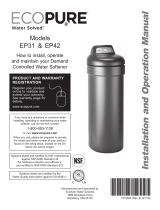
Whirlpool WHES18 User manual

Type
User manual
PRODUCT REGISTRATION
AND WARRANTY EXTENSION
Please register your product on
whirlpoolwatersolutions.com
See warranty page for
extended warranty details.
How to install, operate
and maintain your Demand
Controlled Water Softener
Model WHES18
7385281 (Rev. D 9/12/23)
Manufactured and warranted by
Water Channel Partners
1890 Woodlane Drive
Woodbury, MN 55125
System tested and certified by NSF International
against NSF/ANSI Standard 44
for hardness reduction and efficiency,
and certified to NSF/ANSI/CAN Standard 372.
®
If you have any questions or concerns when
installing, operating or maintaining your water
softener, call our toll free number:
1-866-986-3223
or visit whirlpoolwatersolutions.com
When you call, please be prepared to provide
the model and serial number of your product,
found on the rating decal, typically located on
the rim below the salt lid.
Installation and Operation Manual
2
TABLE OF CONTENTS
Page
Specifications & Performance Claims . . . . . . . . . . . . . . . . . . . . . . . . . . . . . . . . . . . . . . . . . . . . . . . . . . . . . . . . . . . . 3
Water Softener Safety . . . . . . . . . . . . . . . . . . . . . . . . . . . . . . . . . . . . . . . . . . . . . . . . . . . . . . . . . . . . . . . . . . . . . . . . 4
Before You Start . . . . . . . . . . . . . . . . . . . . . . . . . . . . . . . . . . . . . . . . . . . . . . . . . . . . . . . . . . . . . . . . . . . . . . . . . . . . 4
Inspect Shipment . . . . . . . . . . . . . . . . . . . . . . . . . . . . . . . . . . . . . . . . . . . . . . . . . . . . . . . . . . . . . . . . . . . . . . . . . . . . 5
Water Conditioning Information . . . . . . . . . . . . . . . . . . . . . . . . . . . . . . . . . . . . . . . . . . . . . . . . . . . . . . . . . . . . . . . . . 5
Installation Requirements . . . . . . . . . . . . . . . . . . . . . . . . . . . . . . . . . . . . . . . . . . . . . . . . . . . . . . . . . . . . . . . . . . . . 6-7
Installation Instructions . . . . . . . . . . . . . . . . . . . . . . . . . . . . . . . . . . . . . . . . . . . . . . . . . . . . . . . . . . . . . . . . . . . . 8-11
Programming the Water Softener . . . . . . . . . . . . . . . . . . . . . . . . . . . . . . . . . . . . . . . . . . . . . . . . . . . . . . . . . . . 12-13
Customizing Features / Options . . . . . . . . . . . . . . . . . . . . . . . . . . . . . . . . . . . . . . . . . . . . . . . . . . . . . . . . . . . . . 13-14
Routine Maintenance . . . . . . . . . . . . . . . . . . . . . . . . . . . . . . . . . . . . . . . . . . . . . . . . . . . . . . . . . . . . . . . . . . . . . 15-16
Troubleshooting . . . . . . . . . . . . . . . . . . . . . . . . . . . . . . . . . . . . . . . . . . . . . . . . . . . . . . . . . . . . . . . . . . . . . . . . . 17-18
Exploded View & Parts List . . . . . . . . . . . . . . . . . . . . . . . . . . . . . . . . . . . . . . . . . . . . . . . . . . . . . . . . . . . . . . . . 20-23
Warranty . . . . . . . . . . . . . . . . . . . . . . . . . . . . . . . . . . . . . . . . . . . . . . . . . . . . . . . . . . . . . . . . . . . . . . . . . . . . . . . . . 24
Dimensions
FIG. 1
3-3/8"
INLET
21-1/4"
INLET -
OUTLET
OUTLET
14-1/2"
FRONT VIEWSIDE VIEW
TOP VIEW
30-1/4"
23"
3
Specifications & Performance Claims
This model is efficiency rated. The efficiency rating is valid only at the minimum salt dose. The softener has a
demand initiated regeneration (D.I.R.) feature that complies with specific performance specifications intended to
minimize the amount of regenerant brine and water used in its operation.
This softener has a rated softener efficiency of not less than 3,350 grains of total hardness exchange per pound of
salt (based on sodium chloride) and shall not deliver more salt than its listed rating or be operated at a sustained
maximum service flow rate greater than its listed rating. This softener has been proven to deliver soft water for at
least ten continuous minutes at the rated service flow rate. The rated salt efficiency is measured by laboratory tests
described in NSF/ANSI Standard 44. These tests represent the maximum possible efficiency that the system can
achieve. Operational efficiency is the actual efficiency after the system has been installed. It is typically less than
the rated efficiency, due to individual application factors including water hardness, water usage, and other
contaminants that reduce a softener's capacity.
*Capacity to reduce clear water iron is substantiated by laboratory test data. State of Wisconsin
requires additional treatment if the water supply contains clear water iron exceeding 5 ppm.
**Intermittent flow rate does not represent the maximum service flow rate used for determining
the softener’s rated capacity and efficiency. Continuous operation at flow rates greater than
the service flow rate may affect capacity and efficiency performance.
This system conforms to NSF/ANSI 44 for the specific performance claims as verified and
substantiated by test data.
Variable Salt Dose: The salt dose is selected by the electronic controls at regeneration time
based on the amount needed.
Model WHES18
Model Code LE18
Rated Softening Capacity (Grains @ Salt Dose)
7,600 @ 1.8 lbs.
11,000 @ 3.1 lbs.
18,500 @ 10.8 lbs.
Rated Efficiency (Grains/Pound of Salt @ Minimum Salt Dose) 4,100 @ 1.8 lbs.
Water Used During Regeneration @ Minimum Salt Dose 3.0 gal. / 1,000 grains
Total Water Used Per Regeneration @ Maximum Salt Dose 26.4 gallons
Rated Service Flow Rate 7.0 gpm
Amount of High Capacity Ion Exchange Resin .64 cu. ft.
Pressure Drop at Rated Service Flow 9.5 psig
Water Supply Max. Hardness 65 gpg
Water Supply Max. Clear Water Iron 3 ppm*
Water Pressure Limits (minimum / maximum) 20 - 125 psi
Water Temperature Limits (minimum / maximum) 40 - 120 °F
Minimum Water Supply Flow Rate 3 gpm
Intermittent Flow @ 15 PSI 9.0 gpm**
Maximum Drain Flow Rate 2.0 gpm
Salt Storage Capacity 125 lbs.
Questions? Call Toll Free 1-866-986-3223 or visit whirlpoolwatersolutions.com
When you call, please be prepared to provide the model and serial number,
found on the rating decal, typically located on the rim below the salt lid.
4
Water Softener Safety
Your safety and the safety of others are very important.
We have provided many safety messages in this manual and on your appliance. Always read and obey all safety
messages.
This is the safety alert symbol.
This symbol alerts you to potential hazards that can kill or hurt you and others.
All safety messages will follow the safety alert symbol and either the word “DANGER” or “WARNING”
These words mean:
You can be killed or seriously injured if you don’t
immediately follow instructions.
You can be killed or seriously injured if you don’t
follow instructions.
All safety messages will tell you what the potential hazard is, tell you how to reduce the chance of injury, and tell
you what can happen if the instructions are not followed.
In the state of Massachusetts: The Commonwealth of Massachusetts plumbing code 248-CMR shall
be adhered to. A licensed plumber shall be used for this installation.
In the state of California: You must turn the Salt Efficiency Feature setting to ON. This may initiate
more frequent recharges. However, it will operate at 4,000 grains per pound of salt or higher. To turn
on the Salt Efficiency Feature, follow the instructions in the “Salt Efficiency” section of this manual.
Before You Start
= The water softener requires a minimum water flow of 3 gallons per minute at the inlet. The maximum allowable
inlet water pressure is 125 psi. If daytime pressure is over 80 psi, nighttime pressure may exceed the maximum.
Use a pressure reducing valve if necessary (Adding a pressure reducing valve may reduce the flow). If your
home is equipped with a backflow preventer, an expansion tank must be installed in accordance with local codes
and laws.
= The water softener works on 24 V DC electrical power supplied by a direct plug-in power supply (included). Be
sure to use the included power supply and plug it into a nominal 120 V, 60 Hz household outlet that is in a dry
location only, grounded and properly protected by an overcurrent device such as a circuit breaker or fuse.
= Do not use this system to treat water that is microbiologically unsafe or of unknown quality without adequate
disinfection upstream or downstream of the system.
European Directive 2002/96/EC requires all electrical and electronic equipment to be disposed of
according to Waste Electrical and Electronic Equipment (WEEE) requirements. This directive or similar
laws are in place nationally and can vary from region to region. Please refer to your state and local laws
for proper disposal of this equipment.
Do not return the water softener to store.
If you have any questions, or there are missing parts or damage, please call Toll Free 1-866-986-3223
or visit www.whirlpoolwatersolutions.com
When you call, please be prepared to provide the model and serial number, found on the rating decal,
typically located on the rim below the salt lid hinges.
5
Water Conditioning Information
IRON
Iron in water can cause stains on clothing and plumbing
fixtures. It can negatively affect the taste of food,
drinking water, and other beverages. Iron in water is
measured in parts per million (ppm). The total* ppm of
iron, and type or types*, is determined by chemical
analysis. Four different types of iron in water are:
= Ferrous (clear water) iron
= Ferric (red water) iron
= Bacterial and organically bound iron
= Colloidal and inorganically bound iron (ferrous or
ferric)
Ferrous (clear water) iron is soluble and dissolves in
water. This water softener will reduce moderate
amounts of this type of iron (see specifications).**
Ferrous (clear water) iron is usually detected by taking
a sample of water in a clear bottle or glass.
Immediately after taking, the sample is clear. As the
water sample stands, it gradually clouds and turns
slightly yellow or brown as air oxidizes the iron. This
usually occurs in 15 to 30 minutes.
When using the softener to reduce Ferrous (clear
water) iron, add 5 grains to the hardness setting for
every 1 ppm of Ferrous (clear water) iron. See "Set
Water Hardness Number" section.
Ferric (red water), and bacterial and organically bound
irons are insoluble. This water softener will not
remove ferric or bacterial iron. This iron is visible
immediately when drawn from a faucet because it has
oxidized before reaching the home. It appears as a
small cloudy yellow, orange, or reddish suspended
particles. After the water stands for some time, the
particles settle to the bottom of the container.
Generally, these irons are removed from water by
filtration. Chlorination is also recommended for
bacterial iron.
Colloidal and inorganically bound iron is of ferric or
ferrous form that will not filter or exchange out of
water. This water softener will not remove colloidal
iron. In some instances, treatment may improve
colloidal iron water. Colloidal iron water usually has a
yellow appearance when drawn. After standing for
several hours, the color persists and the iron does not
settle but remains suspended in the water.
SEDIMENT
Sediment is fine foreign material particles suspended
in water. This water softener will not remove sediment.
This material is most often clay or silt. Extreme
amounts of sediment may give the water a cloudy
appearance. A sediment filter installed upstream of
the water softener normally corrects this situation.
* Water may contain one or more of the four types of
iron and any combination of these. Total iron is the
sum of the contents.
** Capacity to reduce clear water iron is substantiated
by laboratory test data.
Packing List
Inspect Shipment
The parts required to assemble and install the water
softener are included with the unit. Thoroughly check
the water softener for possible shipping damage and
parts loss. Also, inspect and note any damage to the
shipping carton.
Remove and discard (or recycle) all packing materials.
To avoid the loss of small parts, we suggest you keep
the small parts in the parts bag until you are ready to
use them.
Drain HoseBypass Valve
Clips
(shipped installed on
the softener’s valve)
Adaptor Elbow FIG. 2
Hose Clamps Grommet
Water Hardness
Test Strip
Silicone Grease
6
Installation Requirements
PLUMBING CODES
All plumbing must be completed in accordance with
national, state, and local plumbing codes.
LAUNDRY TUBSTANDPIPE
1-1/2"
air gap
FLOOR DRAIN
In the state of Massachusetts: The Commonwealth
of Massachusetts plumbing code 248-CMR shall
be adhered to. A licensed plumber shall be used
for this installation.
AIR GAP REQUIREMENTS
A drain is needed for regeneration water (See Figure
3). A floor drain, close to the water softener, is
preferred. Alaundry tub, standpipe, etc. are other
drain options. Secure valve drain hose in place.
Leave an air gap of 1-1/2" between the end of the
hose and the drain. This gap is needed to prevent the
backflow of sewer water into the water softener. Do
not put the end of the drain hose into the drain.
FIG. 3
1-1/2"
air gap
Drain
Hose
Drain
Hose
1-1/2"
air gap
LOCATIONREQUIREMENTS
Consider all of the following when selecting an
installation location for the water softener.
= Do not locate the water softener where freezing
temperatures occur. Do not attempt to treat water
over 120ºF. Freezing temperatures or hot water
damage voids the warranty.
= To condition all water in the home, install the water
softener close to the water supply inlet, and
upstream of all other plumbing connections, except
outside water pipes. Outside faucets should remain
on hard water to avoid wasting conditioned water
and salt.
= A nearby drain is needed to carry away regenera-
tion discharge (drain) water. Use a floor drain,
laundry tub, sump, standpipe, or other options
(check your local codes). See "Air Gap
Requirements" and "Valve Drain Requirements"
sections.
= The water softener works on 24 V DC electrical
power, supplied by a direct plug-in power supply
(included). Provide nearby a 120 V, 60 Hz electrical
outlet in accordance with NEC and local codes.
= Always install the water softener between the water
inlet and water heater. Any other installed water
conditioning equipment should be installed between
the water inlet and water softener (See Figure 4
below).
= Avoid installing in direct sunlight. Excessive sun
heat may cause distortion or other damage to non-
metallic parts.
THE PROPER ORDER TO INSTALL WATER TREATMENT EQUIPMENT
FIG. 4
Pressure
Tank
City Water Supply
Well Water Supply
Well
Pump
OR
Optional
Sediment
Filter
Water
Heater
Water
Softener
Untreated Water to
Outside Faucets
Hot Water
to House
Cold Water
to House
Drain
Hose
7
Installation Requirements
FIG. 6
Clip
Barbs
1/4 NPT
Threads
1/2" Outside Dia.
Copper Tube
(not included)
Compression Fitting.
1/4 NPT x 1/2” O.D.
Tube (not included)
Cut barbs from drain fit-
ting (pull clip to remove
fitting from valve)
VALVE DRAIN REQUIREMENTS
Using the flexible drain hose (included), measure and
cut to the length needed. Flexible drain hose is not
allowed in all localities (check your plumbing codes). If
local codes do not allow the use of a flexible drain
hose, a rigid valve drain run must be used. Purchase
a compression fitting (1/4 NPT x 1/2 in. minimum tube)
and 1/2" tubing from your local hardware store. Plumb
a rigid drain as needed (See Figure 6).
NOTE: Make the valve drain line as short and direct
as possible.
INLET / OUTLET PLUMBING OPTIONS
Always install either a single bypass valve (provided),
as shown in Figure 7, or, if desired, parts for a 3 valve
bypass system (not included) can be purchased and
assembled, as shown in Figure 8. Bypass valves allow
you to turn off water to the softener for maintenance if
needed, but still have water in house pipes.
Use:
= Copper pipe
= Threaded pipe
= PEX (Crosslinked Polyethylene) pipe
= CPVC plastic pipe
= Other pipe approved for use with potable water
IMPORTANT: Do not solder with plumbing attached to
the single bypass valve. Soldering heat
will damage the plastic valve.
FIG. 8
3 VALVE BYPASS
From Water
Softener
To Water
Softener
Inlet
Valve
Outlet
Valve
Bypass
Valve
FIG. 5
1/4" NPT
Thread Barbs for 3/8"
I.D. Tubing
Drain Hose
Hose Clamp
FIG. 7
SINGLE BYPASS VALVE
Pull out for “Service”
(Soft water)
Push in for
“Bypass”
Electrical Shock Hazard
Prior to installation on metallic plumbing,
securely install two grounding clamps and a
#4 copper wire per installation instructions.
Failure to follow these instructions can result
in death or electrical shock.
8
TURN OFF WATER SUPPLY
1. Close the main water supply valve, located near the
well pump or water meter.
2. Open all faucets to drain all water from house pipes.
NOTE: Be sure not to drain water from the water
heater, as damage to the water heater
elements could result.
INSTALL THE BRINE TANK OVERFLOW
ELBOW
Install the brine tank overflow grommet and elbow in
the 13/16" diameter hole in the back of the salt storage
tank sidewall.
NOTE: The brine tank overflow elbow accepts either
1/2" or 3/8" I.D. hose.
1. Move the water softener into the desired location.
Set it on a solid, level surface.
IMPORTANT: Do not place shims directly under the salt
storage tank to level the softener. The
weight of the tank, when full of water and
salt, may cause the tank to fracture at the
shim.
2. Visually check and remove any debris from the water
softener valve inlet and outlet ports.
3. Make sure the turbine assembly spins freely in the
"out" port of the valve.
4. If not already done, put a light coating of silicone
grease on the single bypass valve o-rings.
5. Push the single bypass valve into the softener valve
as far as it will go. Snap the two large holding clips
into place, from the top down as shown in Figures 11
& 12.
IMPORTANT: Be sure the clips snap firmly into place so
the single bypass valve will not pull out.
MOVE THE WATER SOFTENER INTO PLACE
Excessive Weight Hazard
Use two or more people to move and install
water softener.
Failure to do so can result in back or other
injury.
FIG. 9
TYPICAL INSTALLATION
Outlet
Clips
To Outside
Faucets
1-1/2"
air gap
Conditioned
Water
Hard Water
Main Water Pipe
Plug-in
Power
Supply
Water Softener
Valve
To
Controller
Valve Drain
Elbow
Valve Drain
Hose*
*Do not connect the
water softener valve
drain tubing to the salt
storage tank overflow hose. Floor Drain
Overflow
Drain Elbow
Salt Storage
Tank Overflow
Hose*
Secure Valve Drain Hose
in place over Floor Drain
NOTE: Water Softener
shown with
Salt Lid and Top
Cover removed
NOTE: See “Air Gap Requirements” section.
Pipes
1" NPT Sweat
Adaptors (not
included)
Single
Bypass Valve
Inlet
Lubricated
O-rings
Installation Instructions
9
Installation Instructions
FIG. 11
Clip
Channel
Single Bypass Valve
FIG. 12
CORRECT ASSEMBLY
Clip
Outside diameter
of clip channel on
single bypass valve
Outside diameter
of water softener
valve inlet & outlet
NOTE: Be sure all 3 tabs of the clip go through the matching
holes on the water softener valve inlet or outlet, and
fully into the channel on the single bypass valve.
Make sure that the tabs are fully seated.
FIG. 13
Ground Wire
(not included)
Clamp
(2 - not included)
Electrical Shock Hazard
Prior to installation on metallic plumbing,
securely install two grounding clamps and a
#4 copper wire per installation instructions.
Failure to follow these instructions can result
in death or electrical shock.
GROUNDING INFORMATION
(for Installations on Metal Pipe)
The house main incoming water pipe is often used to
ground electrical outlets in the home. Grounding
protects you from electrical shock. Installing the water
softener with a plastic bypass valve will break this
ground. Before beginning installation, purchase and
securely install two grounding clamps and a #4 copper
wire across the location where the softener will be,
tightly clamping it at both ends, as shown in Figure 13.
NOTE: Check local plumbing and electrical codes for
the proper installation of the ground wire. The
installation must conform to them. In
Massachusetts, plumbing codes of
Massachusetts shall be conformed to.
Consult with your licensed plumber.
FIG. 10
Brine Tank
Overflow
Elbow
Brine Tank
Overflow
Grommet
Brinewell
Cover
Brinewell
Brine
Valve
Salt
Storage
Tank
Brine
Tubing
Nut -
Ferrule
Nozzle
Venturi
Assembly
Brine
Tubing
10
Installation Instructions
COMPLETE INLET AND OUTLET PLUMBING
Measure, cut, and loosely assemble pipe and fittings
from the main water pipe to the inlet and outlet ports of
the water softener valve. Be sure to keep fittings fully
together, and pipes squared and straight.
Be sure hard water supply pipe goes to the water
softener valve inlet side.
NOTE: Inlet and outlet are marked on the water softener
valve. Trace the water flow direction to be sure
hard water is to inlet.
IMPORTANT: Be sure to fit, align and support all
plumbing to prevent putting stress on the
water softener valve inlet and outlet.
Stress from misaligned or unsupported
plumbing may cause damage to the
valve.
Complete the inlet and outlet plumbing for the type of
pipe you will be using.
INSTALL VALVE DRAIN HOSE
1. Measure, cut to needed length and connect the 3/8"
drain line (provided) to the water softener valve drain
fitting. Use a hose clamp to hold the hose in place.
NOTE: Make the valve drain line as short and direct as
possible.
IMPORTANT: If codes require a rigid drain line see
“Valve Drain requirements" section.
2. Route the drain hose or copper tubing to the floor
drain. Secure drain hose. This will prevent
“whipping'' during regenerations. See “Air Gap
Requirements" section.
1. Measure, cut to needed length and connect the 3/8"
drain line (provided) to the salt storage tank overflow
elbow and secure in place with a hose clamp.
2. Route the hose to the floor drain, or another suitable
drain point no higher than the drain fitting on the salt
storage tank (this is a gravity drain). If the tank
overfills with water, the excess water flows to the
drain point. Cut the drain line to the desired length
and route it neatly out of the way.
IMPORTANT: For proper operation of the water
softener, do not connect the water
softener valve drain tubing to the salt
storage tank overflow hose.
INSTALL SALT STORAGE TANK OVERFLOW
HOSE
TEST FOR LEAKS
To prevent air pressure in the water softener and
plumbing system, complete the following steps in
order:
1. Fully open two or more softened cold water faucets
close to the water softener, located downstream
from the water softener.
2. Place the bypass valve (single or 3 valve) into the
"bypass" position. See Figures 7 & 8 on Page 7.
3. Slowly open the main water supply valve. Run
water until there is a steady flow from the opened
faucets, with no air bubbles.
4. Place bypass valve(s) in "service" or soft water
position as follows:
= Single bypass valve: Slowly move the valve stem
toward "service," pausing several times to allow
the water softener to fill with water.
= 3 valve bypass: Fully close the bypass valve and
open the outlet valve. Slowly open the inlet
valve, pausing several times to allow the water
softener to fill with water.
5. After about three minutes, open a hot water faucet
until there is a steady flow and there are no air
bubbles, then close this faucet.
6. Close all cold water faucets and check for leaks at
the plumbing connections that you made.
7. Check for leaks around clips at softener’s inlet and
outlet. If a leak occurs at a clip, depressurize the
plumbing (turn off the water supply and open
faucets) before removing the clip. When removing
clips at the softener’s inlet or outlet, push the single
bypass valve body toward the softener (See Figure
14). Improper removal may damage clips. Do not
reinstall damaged clips.
FIG. 14
...depressurize the
plumbing, then push
Bypass Valve body
toward softener
If removing
clips...
11
Excessive Weight Hazard
Use two or more people to move and lift salt
bags.
Failure to do so can result in back or other
injury.
ADD WATER AND SALT TO THE SALT
STORAGE TANK
Installation Instructions
1. Using a container, add about three gallons of clean
water into the salt storage tank.
2. Add salt to the storage tank. Use nugget, pellet, or
coarse solar salts with less than 1% impurities.
PLUG IN THE POWER SUPPLY
During installation, the water softener wiring may be
moved or jostled out of its place. Be sure all leadwire
connectors are secure on the back of the electronic
board and be sure all wiring is away from the valve
gear and the motor area, which rotates during
regenerations.
1. Plug the power supply into an electrical outlet that is
not controlled by a switch.
NOTE: The water heater is filled with hard water and,
as hot water is used, it will refill with
conditioned water. In a few days, the hot water
will be fully conditioned. To have fully
conditioned hot water immediately, wait until
the initial recharge is over. Then, drain the
water heater (following instructions for water
heater) until water runs cold.
SANITIZE THE WATER SOFTENER /
SANITIZE AFTER SERVICE
1. Open salt lid, remove the brinewell cover and pour
about 3 oz. (6 tablespoons) of household bleach
into the softener brinewell. Replace the brinewell
cover.
2. Make sure the bypass valve(s) is in the “service”
(open) position.
3. Start a recharge (regeneration).
See “Start a Recharge” on Page 13.
4. After the recharge has completed, fully open a cold
water faucet, downstream from the softener, and
allow 50 gallons of water to pass through the
system. This should take at least 20 minutes.
Close the faucet.
12
Programming the Water Softener
CLEAN REMINDER
The screen in Figure 16 appears, with “CLEAn” flash-
ing in the display, when four months have elapsed on
the system’s timer since start up or the last reset.
FIG. 16
This is a reminder to use Whirlpool® WHE-WSC
Water Softener Cleanser three times a year. To reset
the timer, press any button on the control panel and
“CLEAn” will disappear.
PROGRAM THE SOFTENER
When the power supply is plugged into the electrical
outlet, the model code (LE18) and a software version
number (example: J3.9), are briefly shown in the
display. Then the words “PRESENT TIME” appear
and 12:00 PM begins to flash.
FIG. 15
UP button
DOWN
button
Display
RECHARGE
button
PROGRAM
button
Questions? Call Toll Free 1-866-986-3223 or visit whirlpoolwatersolutions.com
When you call, please be prepared to provide the model and serial number,
found on the rating decal, typically located on the rim below the salt lid.
SET TIME OF DAY
If the words “PRESENT TIME” do not show in the
display, press the PROGRAM button until they do.
1. Press the r UP or s DOWN buttons to set the
present time. Up moves the display ahead; down
sets the time back. Be sure AM or PM is correct.
NOTE: Press buttons and quickly release to slowly
advance the display. Hold the buttons down
for fast advance.
SET WATER HARDNESS NUMBER
1. Press the PROGRAM button once again to display
a flashing “25” and the word “HARDNESS”.
FIG. 17
FIG. 18
2. Press the r UP or s DOWN buttons to set your
water’s hardness number.
RECHARGE NOW initiated
RECHARGE NOW
The RECHARGE button is used to initiate an
immediate recharge.
1. Press and hold the RECHARGE button until the
words “RECHARGE NOW” flash in the display.
The softener enters the fill cycle of regeneration right
away. “RECHARGE NOW” will flash during the
regeneration. When completed, full water conditioning
capacity is restored. While water softener is running
a recharge, the time remaining until the recharge is
completed will show in the display during all cycles
except for the Fill cycle.
NOTE: Avoid using hot water while the softener is
regenerating, because the water heater will
refill with bypass hard water.
RECHARGE TONIGHT
If you do not want to start an immediate recharge, but
would like to schedule an extra recharge at the next
preset recharge time, do the following:
1. Press and release (do not hold) the RECHARGE
button.
FIG. 20
13
Programming the
Water Softener
NOTE: If your water supply contains iron, compensate
for it by adding to the water hardness number.
For example, assume your water is 20 gpg
hard and contains 2 ppm iron. Add 5 to the
hardness number for each 1 ppm of iron. In
this example, you would use 30 for your
hardness number.
20 gpg hardness
2 ppm iron x 5 = 10 +10
(times) 30 HARDNESS NUMBER
NOTE: If you use potassium chloride (KCl) salt
instead of sodium chloride (NaCl) salt in this
softener, increase the hardness setting by
25%. For example, if you will be using KCl
and your water supply’s hardness is 20 gpg,
set the softener to 25 gpg.
SET RECHARGE (REGENERATION) TIME
1. Press the PROGRAM button once again to display
a flashing 2:00 AM and the words “RECHARGE
TIME”. This is a good time for the recharge to start
in most households, because water is not in use.
2. If you want to change the recharge start time,
press the r UP or s DOWN buttons until the
desired time shows. Be sure AM or PM is correct.
3. Press the PROGRAM button once again, to return
to the normal time of day display.
START A RECHARGE
1. Press the RECHARGE button and hold for three
seconds, until “RECHARGE” begins to flash in the
display, starting a recharge. This recharge draws
the sanitizing bleach into and through the water
softener. Any air remaining in the water softener is
purged to the drain. During this time, periodically
check for leaks.
NOTE: As with all other water system applications,
leaks may occur. Leaks may not be
immediately apparent. Recheck for leaks 24
hours after the first recharge cycle is complete.
FIG. 19
Customizing
Features / Options
The words “RECHARGE TONIGHT” flash in the
display and the softener will recharge at the next
recharge time. The words “RECHARGE NOW" will
flash during the regeneration. When completed, full
water conditioning capacity is restored.
RECHARGE TONIGHT initiated
FIG. 21
14
Customizing Features / Options
In the state of California: You must turn the Salt
Efficiency Fea ture ON. This may initiate more
frequent recharges. However, it will operate at
4,000 grains per pound of salt or higher.
SALT EFFICIENCY
When this feature is ON, the water softener will
operate at salt efficiencies of 4000 grains of hardness
per pound of salt or higher (May recharge more often
using smaller salt dosage and less water). The
softener is shipped with this feature set OFF.
1. Press and hold the PROGRAM button until one of
the screens in Figure 22 is displayed. Once in this
display, press the PROGRAM button once, and
one of the two displays in Figure 23 is shown.
2. Press the r UP or s DOWN buttons to set ON or
OFF. When set to ON, the efficiency icon will be
displayed in the upper right hand corner of the
normal run display.
FIG. 24
FIG. 22
FIG. 23
Efficiency Icon
3. Press the PROGRAM button three times to return
to the normal run display (See Figure 24).
Displayed when efficiency
is set to “ON”
MAXIMUM DAYS BETWEEN REGENERA-
TIONS
The water softener automatically controls regeneration
frequency. This provides the greatest operating
efficiency and, under most conditions, this feature
should be left in this automatic mode. However, you
may modify this feature if you want to force a
regeneration every set number of days. For example,
if your water supply contains clear water iron, you
may want the softener to regenerate every few days
to keep the resin bed clean. The maximum days
between recharges may be set from 1 to 15 days, as
follows:
NOTE: The softener will recharge on its own if need-
ed, even if it is before the set number of days.
1. Press and hold the PROGRAM button until the
screen in Figure 22 is displayed. Once in this
display, press the PROGRAM button two times,
and the display in Figure 25 is shown.
2. Press the r UP or s DOWN buttons to set the
number of days.
3. Press the PROGRAM button twice to return to the
normal time of day screen.
12 OR 24 HOUR CLOCK
At the default setting, all clock displays are shown in
12 hour time format (AM and PM). If 24 hour time
format is desired, follow the steps below:
1. Press and hold the PROGRAM button until the
screen in Figure 22 is displayed. Once in this
display, press the PROGRAM button three times
and one of the two displays in Figure 26 is shown.
2. Press the r UP or s DOWN buttons to set the
time format.
3. Press the PROGRAM button once again, to return
to the normal time of day screen.
FIG. 25
FIG. 26
15
Routine Maintenance
WATER SOFTENER CLEANSER
The manufacturer recommends that you use
Whirlpool® WHE-WSC Water Softener Cleanser, as
directed, every four months.
Lift the brinewell cover and pour in the entire 16 oz.
bottle of Whirlpool® Water Softener Cleanser. Press
the RECHARGE button and hold for three seconds,
until “RECHARGE” begins to flash in the display.
This manual recharge will take about two hours. If
taste, odor, or discoloration are detected in the water,
manually recharge the softener again, then run a cold
water faucet immediately downstream of the softener
until water tastes, smells, and appears normal.
POWER OUTAGE MEMORY
If electrical power to the water softener is lost,
“memory” built into the timer circuitry will keep all
settings for several hours. While the power is out, the
display is blank and the water softener will not
regenerate. When electrical power is restored, the
following will occur:
Reset the present time only if the display is flashing.
The HARDNESS and RECHARGE TIME never
require resetting unless a change is desired. Even if
the clock is incorrect after a long power outage, the
softener operates as it should to keep your water soft.
However, regenerations may occur at the wrong time
of day until you reset the clock to the correct time of
day.
NOTE: If the water softener was regenerating when
power was lost, it will now finish the cycle.
16
FIG. 28
Cap
O-ring Seal
Screen Support
Screen
Gasket
*Flow Plug (HVDC)
Housing
Ferrule
Nut
Cone Screen
*Flow Plug
*Install with lettered
side up, concave
side down.
CLEANING THE NOZZLE & VENTURI
A clean nozzle & venturi (See Figure 28) is a necessity
for the water softener to work properly. This small
component creates the suction to move brine from the
brine tank, into the resin tank. If it should become
plugged with sand, silt, dirt, etc., the water softener will
not work, and hard water will result.
Nozzle & Venturi Disc
IMPORTANT: Be sure small hole in the gasket is
centered directly over the small hole in the nozzle &
venturi housing. Be sure the numbers are facing up.
Routine Maintenance
ADDING SALT
Lift the salt lid and check the salt storage level
frequently. If the water softener uses all the salt
before you refill it, you will experience hard water.
Until you have established a refilling routine, check the
salt every two or three weeks. Always add if less than
1/4 full. Be sure the brinewell cover is on.
NOTE: If using potassium chloride (KCl), do not fill
above level 4 on the brinewell decal.
NOTE: In humid areas, it is best to keep the salt
storage level lower, and to refill more often to
avoid salt “bridging”.
Recommended Salt: Nugget, pellet, or coarse solar
salts with less than 1% impurities.
Salt Not Recommended: Rock salt, high in impurities,
block, granulated, table, ice melting, ice cream making
salts, etc.
BREAKING A SALT BRIDGE
Sometimes, a hard crust or salt “bridge” forms in the
brine tank. It is usually caused by high humidity or the
wrong kind of salt. When the salt “bridges,” an empty
space forms between the water and the salt. Then,
salt will not dissolve in the water to make brine.
Without brine, the resin bed is not recharged and hard
water will result.
If the storage tank is full of salt, it is difficult to tell if
you have a salt bridge. A bridge may be underneath
loose salt. Take a broom handle, or like tool, and hold
it next to the water softener. Measure the distance
from the floor to the rim of the water softener. Then,
gently push the broom handle straight down into the
salt. If a hard object is felt before the pencil mark is
even with the top, it is most likely a salt bridge. Gently
push into the bridge in several places to break it. Do
not use any sharp or pointed objects as you may
puncture the brine tank. Do not try to break the salt
bridge by pounding on the outside of the salt tank.
You may damage the tank.
To get access to the nozzle & venturi, remove the
water softener’s top cover. Put the bypass valve(s)
into the bypass position. Be sure the water softener is
in the soft water (service) cycle (no water pressure at
nozzle & venturi). Then, holding the nozzle & venturi
housing with one hand, un screw the cap. Do not lose
the o-ring seal. Lift out the screen support and screen.
Then, remove the nozzle & venturi disc, gasket, and
flow plug(s). Wash the parts in warm, soapy water
and rinse in fresh water. Be sure to clean both the top
and bottom of the nozzle & venturi disc. If needed,
use a small brush to remove iron or dirt. Do not
scratch, misshape, etc., surfaces of the nozzle &
venturi.
Gently replace all parts in the correct order. Lubricate
the o-ring seal with silicone grease and locate in place.
Install and tighten the cap by hand, while supporting
the housing. Overtightening may break the cap or
housing. Put the bypass valve(s) into service (soft
water) position.
Recharge the softener to reduce the water level in the
tank. This will also assure that the softener is
completely recharged and ready to provide softened
water again. Check the water level in the tank by look-
ing down the brinewell. If the water level does not
drop after a recharge, the problem has not been
resolved. Call 1-866-986-3223.
Broom
Handle
Pencil
Mark
Salt
Salt
Bridge
Water
Level
Push Tool into
Salt Bridge to
Break
1" - 2"
FIG. 27
17
While an error code appears in the display, all buttons
are inoperable except the PROGRAM button.
PROGRAM remains operational so the service
person can perform the Manual Advance Diagnostics,
see below, to further isolate the problem.
Procedure for removing error code from
display:
1. Unplug transformer from electrical outlet.
2. Correct problem.
3. Plug in transformer.
4. Wait 8 minutes. The error code will return if
the problem was not corrected.
MANUAL ADVANCE DIAGNOSTICS
Use the following procedures to advance the water
softener through the regeneration cycles to check
operation.
Lift off the salt lid, remove the top cover by unlocking
the tabs in the back and rocking forward, to observe
cam and switch operation during valve rotation.
1. Press and hold PROGRAM for 3 seconds until
“000” shows in the display, then release.
2. The 3 digits indicate water meter operation as
follows:
000 (steady) = Soft water not in use, and no flow
through the meter.
Open a nearby soft water faucet.
000 to 199 (continual) = Repeats for each gallon
of water passing through
the meter.
3. The letter “P” and a dash (or dashes) indicate
POSITION switch operation (See Figure 30). If the
letter appears, the switch is closed. If the dash
shows, the switch is open.
4. Use the RECHARGE button to manually advance
the valve into each cycle and check correct switch
operation.
NOTE: Be sure water is in contact with the salt, and
not separated by a salt bridge (See "Breaking
A Salt Bridge" section).
5. While in this diagnostic screen, the following
information is available and may be beneficial for
various reasons. This information is retained by
the computer from the first time electrical power is
applied to the electronic controller.
a. Press the r UP button to display the number of
days this electronic control has had electrical
power applied.
b. Press the s DOWN button to display the
number of regenerations initiated by this elec-
tronic control since the code number was
entered.
6. Press and hold the PROGRAM button until the
model code (LE18) shows in the display. This
code identifies the softener model. If an incorrect
model code is displayed, the softener will operate
on incorrect configuration data.
7. To change the code number, press the r UP or
s DOWN button until the correct code shows.
8. To return to the present time display, press the
PROGRAM button.
Water
Meter
Switch
AUTOMATIC ELECTRONIC DIAGNOSTICS
This water softener has a self-diagnostic function for
the electrical system (except input power and/or water
meter). The water softener monitors electronic
components and circuits for correct operation. If a
malfunction occurs, an error code appears in the
display.
Troubleshooting
FIG. 31
FIG. 29
FIG. 30
Need help troubleshooting? Call Toll Free 1-866-986-3223 or visit whirlpoolwatersolutions.com
When you call, please be prepared to provide the model and serial number,
found on the rating decal, typically located on the rim below the salt lid.
18
Troubleshooting
This check verifies proper operation of the valve
motor, brine tank fill, brine draw, regeneration flow
rates, and other controller functions. Always make
the initial checks, and the manual initiated
diagnostics.
NOTE: The electronic control display must show a
steady time (not flashing). If an error code
shows, first press the PROGRAM button to
enter the diagnostic display.
1. Press the RECHARGE button and hold in for 3
seconds. RECHARGE begins to flash as the
softener’s valve advances from the service to fill
position. Remove the brinewell cover and, using a
flashlight, observe fill water entering the tank.
If water does not enter the tank, look for an
obstructed nozzle, venturi, fill flow plug, brine
tubing, or brine valve riser pipe.
MANUAL ADVANCE REGENERATION CHECK
2. After observing fill, press the RECHARGE button to
move the softener’s valve into the brine position. A
slow flow of water to the drain will begin. Verify
brine draw from the brine tank by shining a
flashlight into the brinewell and observing a
noticeable drop in the liquid level. This may take
15 to 20 minutes.
NOTE: Be sure water is in contact with the salt, and
not separated by a salt bridge (See "Breaking
A Salt Bridge" section).
If the water softener does not draw brine, check for
(most likely to least likely):
= Dirty or plugged nozzle and venturi, see
"Cleaning the Nozzle and Venturi" section.
= Nozzle and venturi not seated on the gasket, or
gasket deformed.
= Valve seals leaking (See Troubleshooting).
= Restriction in valve drain, causing a back-pressure
(bends, kinks, elevated too high, etc.). See
"Install Valve Drain Hose" section.
= Obstruction in brine valve or brine tubing.
NOTE: If water system pressure is low, a too-long or
elevated drain hose may cause back
pressure, stopping brine draw. Avoid drain
hose runs longer than 30 feet. Avoid
elevating the hose more than 8 feet above the
floor.
3. Press the RECHARGE button to move the
softener’s valve into the backwash position. Look
for a fast flow of water from the drain hose. Check
that the drain can adequately handle the flow and
volume.
An obstructed flow indicates a plugged top
distributor, backwash flow plug, or drain hose.
4. Press the RECHARGE button to move the
softener’s valve into the fast rinse position. Again
look for a fast drain flow. Allow the softener to
rinse for a few minutes to flush out any brine that
may remain in the resin tank from the brining cycle
test.
5. To return the softener’s valve to the service posi-
tion, press the RECHARGE button.
RESETTING TO FACTORY DEFAULTS
To reset the electronic controller to its factory default
for all settings (time, hardness, etc.):
1. Press the PROGRAM button and hold it until the
display changes twice to show the flashing model
code.
2. Press the r UP button (a few times, if necessary)
to display a flashing “SoS”.
3. Press the PROGRAM button, and the electronic
controller will restart.
4. Set the present time, hardness, etc., as described
on pages 12 & 13.
FIG. 32
Need help troubleshooting? Call Toll Free 1-866-986-3223 or visit whirlpoolwatersolutions.com
When you call, please be prepared to provide the model and serial number,
found on the rating decal, typically located on the rim below the salt lid.
19
Notes
20
Water Softener Exploded View
1
2
3
4
5
6
7
8
9
71
11
12
13
14
17
18
20
19
21
22
23
24
25
26
27
70
Valve Assembly
See Pages 22 & 23
for parts
15
16
10
  • Page 1 1
  • Page 2 2
  • Page 3 3
  • Page 4 4
  • Page 5 5
  • Page 6 6
  • Page 7 7
  • Page 8 8
  • Page 9 9
  • Page 10 10
  • Page 11 11
  • Page 12 12
  • Page 13 13
  • Page 14 14
  • Page 15 15
  • Page 16 16
  • Page 17 17
  • Page 18 18
  • Page 19 19
  • Page 20 20
  • Page 21 21
  • Page 22 22
  • Page 23 23
  • Page 24 24

Whirlpool WHES18 User manual

Type
User manual

Ask a question and I''ll find the answer in the document

Finding information in a document is now easier with AI