Page is loading ...

FIC MB05W Service Manual
FIC MB05 Service Manual 1-1
MB05W
MB05W
(WB-B55)
1.1 Introduction
This chapter provides the outline features and operation of the MB05 including the BIOS
Setup program and other system options.
The MB05 notebook offers the latest in advanced portable computing and multimedia
technology that even outperforms most desktop computers. It incorporates the latest Intel
Pentium - M processor and fully compatibles with an entire library of PC software based on
operating systems such as Windows 2000 / XP. It also runs on future versions of Windows. It
comes with a built-in keyboard, glide pad pointing device, sound system, PCMCIA slots, USB
(Universal Serial Bus) port, IEEE 1394 port, advanced power management and more new
multimedia features.
1.2 Feature Highlights
The MB05 includes a variety of innovative features:
Category Specification Stepping
CPU Intel Pentium – M Processor
: Banias 1.3/1.5 GHZ
Core Logic
Intel Montara-GM (North Bridge) :
CPU(Banias) I/F
VGA Controller
LVDS I/F
DVOB&DVOC IF.
RGB analog I/F
200/266 DDR MEMORY I/F
Hub-Link I/F
Intel ICH4-M (South Bridge) :
Integrated Hub-Link I/F to connect with PCI
Bridge
Dual IDE Master/Slave Controller ,Integrated
DMA Controller
1.1/2.0 Universal Serial Bus Host Controller
Integrated 10/100M Fast Ethernet MAC
Controller
Integrated Audio Controller with AC97 V2.2
Interface
Advanced Power Management(ACPI)
RTC
Integrated PCI to LPC Bridge
Integrated Audio Controller with AC97 Interface
PCI Bus Interface (PCI 2.2 compliant)
GPIO
Advance PIC
PDF created with FinePrint pdfFactory trial version http://www.fineprint.com

FIC MB05W Service Manual
1- 2 FIC MB05 Service Manual
Cache Memory L1 Cache (Pentium Processor internal):
64KB
8-way cache associativity provides
L2 Cache (Pentium Processor internal):
1024KB Advanced Transfer Cache,8 way
associativity
8-way set associative, 32-byte line size, 1 line per
sector
System Memory
Expansion Memory: 2 SO-DIMM Slot (1.25”)
Size: 128/256/512MB/1G
Type: DDR DRAM, 3.3V
Data Path: 64Bit
Frequency : 266MHz
Please refer to the MB05 Key component list in detail.
BIOS ROM Flash ROM
1
st
Vendor : SST 49LF040A PLCC Package 4Mbit LPC
flash ROM
Super I/O SMSC LPC47N267
FDC, IEEE 1284 Printer Port
Serial Port x 1 ports
IR Port ASKIR, SIR, FIR, HPSIR, Consumer IR
Plug and Play Support
RTC + NVRAM Integrated in South Bridge (Intel ICH4-M)
Real Time Clock with 256 byte extended
CMOS.
K/B Controller Mitsubishi M38859 LPC KBC
Internal K/B, Touch Pad, External K/B or M/S
Supported A20Gate,firmware version 2.14
PMU New PMU08
Mitsubishi M38859FFHP
Embedded Controller
TBD
VGA Controller Embedded in Intel Montara-GM
High Performance and high quality 3D
accelerator
Integrated dual DVO bridge
Integrated LVDS Interface
Integrated RGB analog Interface
High performance 2D accelerator
Complete TV-OUT/Digital Flat Panel Solution
VRAM Share system memory, UMA (using DVMT configuration)
8/16/32 MB
TV out encoder None
CardBus
Controller
RICOH R5C554 (PCI Card Bus controller)
PC/Card Bus Type II x1
Build in smart card (none)
Sound
AC’97 CODEC
Realtek ALC202
AC’97 Revision 2.2 Compliant
PDF created with FinePrint pdfFactory trial version http://www.fineprint.com

FIC MB05W Service Manual
FIC MB05 Service Manual 1-3
Modem MDC modem support
V.90, K56flex, ITU-T V.34, V.32, RJ11 Jack
TIA/EIA 602, V.42
ITU-T V.17, V.29, V.27ter, V.21 Ch2
TIA/EIA 578 Class1 FAX
Wake up on Ring
On board LAN Realtek 8100BL
Support LAN boot( no used)
Support for auto-negotiation (10BASE-T and 100BASE-
TX)
Wake up On LAN( S1~S5)
3com Combo
802.11b
802.11 a+b
Support by Intel Calexico Mini-PCI Wireless LAN Card
<Design Ready Only>
1394 RICOH R5C554 PCI-CARDBUS / 1394 OHCI-LINK / 1394
PHY
USB
Intel ICH4-M
Integrated in South Bridge Intel ICH4-M)
Three Independent UHCI USB 1.1 Host Controllers and
One EHCI USB 2.0 Host Controller, support up to six port.
Legacy Keyboard/Mouse support.
Supports only one Debug port at port 1(first port), it is at
USB 2.0 transfer rate..
IDE Interface
(Intel ICH4-M)
Fast IDE:
--Integrated multithreaded I/O link mastering with read
pipelined streaming
--Dual independent IDE channel each with 16 DW FIFO
--Native and compatibility mode
--PIO mode 0,1,2,3,4, and multiword DMA mode 0,1,2
--Ultra DMA 33/66/100
Printer Interface
IEEE 1284-Compatible
SPP mode (PS2 bi-directional mode)
EPP mode (EPP 1.7 and EPP 1.9 IEEE 1284
Compliant)
ECP mode (IEEE 1284 Compliant)
Serial Interface None
External PS/2
Port
(M38859)
External Keyboard or PS/2 Mouse
Exclusively connected.
Can use both device by using branch
cable(option)
Universal Serial
Bus
(Intel ICH4-M)
--INTEL ICH4-M Integrated
--Three Independent OHCI USB 1.1 Host Controllers and
One EHCI USB 2.0 Host Controller, support up to six
port.
--Support up to 6 USB ports
--Support legacy devices
--Over current detection equipped
--Optional configured each port as a wake-up source
Infrared None
Modem 56K Data/Fax Modem (v.90)
LAN 10/100 Base TX LAN
Lan boot support and WFM 2.0
LCD Panel 14.1” XGA
15 XGA
; Please refer to the MB05 Key component list in detail.
PDF created with FinePrint pdfFactory trial version http://www.fineprint.com

FIC MB05W Service Manual
1- 4 FIC MB05 Service Manual
HDD 2.5 inch HDD (Standard)
9.5mm Height
; Please refer to the MB05 Key component list in detail.
CD-ROM
(Option)
CD-ROM (9.5mm Height)
; Please refer to the MB05 Key component list in detail.
.
FDD(None)
USB FDD
3 mode Support
; Please refer to the MB05 Key component list in detail.
DVD
(Option)
DVD
9.5mm Height ,8X
; Please refer to the MB05 Key component list in detail.
CD-RW,Combo 9.5mm Height ,24X
; Please refer to the MB05 Key component list in detail.
Pointing Device Internal Touch Pad
PS/2 mouse I/F
Pad ALPS : KGDDET 005A
Please refer to the MB05T Key component list in detail.
Keyboard Internal Keyboard
6.5mm Height, 3.0mm Stroke, 19mm Pitch
Please refer to the MB05 Key component list in detail.
Speakers
(audio)
Two built-in dynamic speakers
40 x 20mm, 1W 4Ω
Microphone None
Buzzer Not support
Battery Battery Pack
Type: 8 cell Li-ION Battery with EEPROM
Voltage: 14.4V
Capacity: 4400mA(circle);3600mA(square)
Vendor: SANYO
Please refer to the MB05 Key component list in detail.
RTC Battery Ni-MH Battery
Model: CR2032
Voltage: 2.9V
Capacity: 225mAh
Vendor: PANASONIC
DC/DC
Converter
Daughter Board
5.0 V Max 6.0 A
3.3 V Max 6.0 A
12V Max 120mA
2.5V Max 3.5A
1.8V Max 3.5A
CPU Vcore 1.45V Max 22A
AC Adapter ADP75FB : Delta(Consign)
PA-1600-05F : Liteon
Input: AC100 – 240V, 50/60Hz
Output: 19V, 60W Peak 80W(Liteon)
19V.75W(Delta)
Size: 115mm x 50mm x 29mm (Delta)
110mm x 50mm x 29mm (Liteon)
Vendor: Delta or Liteon
Color : TBD
; Please refer to the MB05 Key component list in detail.
Size W=308mm, D=268mm, H=27.7~31mm.
PDF created with FinePrint pdfFactory trial version http://www.fineprint.com

FIC MB05W Service Manual
FIC MB05 Service Manual 1-5
Weight Approx 4.9 lb = 2.2Kg
Battery Handling
Category
Specification
Remark
Power On Li-ion 3.5 h
Battery Charging
Max Change
Current:
1.7A-1.75A±150mA
Power Off Li-ion 3.5 h
Battery Life
1
st
Li-ion 4 h TBD
Save to RAM 1
st
Li-ion 1 Days TBD
Charge 24 h CMOS Battery
Discharge 5 year
System on
System off
Maximum 60W Consumption
power
Typical 30W TBD
PDF created with FinePrint pdfFactory trial version http://www.fineprint.com

FIC MB05W Service Manual
1- 6 FIC MB05 Service Manual
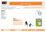
1.3 System Configuration
INTEL
Centrino
INTEL
ICH4-M
LPC47N267
INTEL
MONTARA-G
M
CPU
CORE
GMTG767
ICS950812
CPU PCI CLK
FIC ASIC
F010502-B0
CRT
LCD
USB1 USB0
USB2
DDR SDRAM X 2
MINI PCI
CONN
R5C554
PCMCIA
CNN X 2
G576
1394 PORT
RTL8100BL RJ 45
HD
PHONE
ALC202GMTG1421
MDCRJ11
M38859 PMU08
COM
PORT
4M
ROM
PARALLEL
PS2
INT K/B
GP
RGB
LVDS
32BIT PCI BUS
LPC
MBUS
M BUS
MIC
IN
Figure 1- 1 System Configuration Diagram
PDF created with FinePrint pdfFactory trial version http://www.fineprint.com

FIC MB05W Service Manual
FIC MB05 Service Manual 1-7
1.4 Quick Tour of the Notebook
Please take a moment to become familiar with the location and purpose of every control, the
LED status panel, connectors and ports, which are illustrated in this section. It is
recommended to first go through the User Guide of the notebook, which is shipped together
with the notebook for information on how to operate its features.
1.4.1 The Inside of the Notebook
To open the LCD cover of the notebook, find the cover latch located at the front center of the
LCD cover. Push the latch to the right to release and tilt the LCD cover up. Inside, you will see
the LCD display panel, keyboard, touch pad, status LED, and power switch.
❶
Color LCD Display
❷
Status LED Indicator
❸
Keyboard
❹
Easy Buttons
❺
Power On/Resume
Button
❻
Touchpad Pointing
Device
Figure 1- 2 The Front side of the Notebook
• Color LCD Display
The notebook computer comes with a color LCD that you can adjust for a
comfortable viewing position. The LCD can be 15" TFT color LVDS with
1024x768 XGA (Extended Graphics Array) or 1280x1024 SXGA+ resolution
panels. The features of the Color LCD Display are summarized as follows:
Ÿ TFT color LVDS with 14.1" 1024x768 XGA or 14.1" 1280x1024
SXGA+ resolution panels.
Ÿ Capable of displaying 16M colors (32-bit true color) on either size
panels.
Ÿ LCD display control hot-keys allows you to adjust the brightness of
the LCD.
Ÿ Simultaneous display capability for LCD and external desktop
computer monitor.
PDF created with FinePrint pdfFactory trial version http://www.fineprint.com

FIC MB05W Service Manual
1- 8 FIC MB05 Service Manual
• Easy Buttons
There are three easy buttons used for activating wireless function and
accessing user-defined functions instantly and easily. Description of the easy
buttons appears in the latter part of this section.
• Status LED Indicator
Keeps you informed of your notebook computer’s current power status and
operating status. Description of the status icons appears in the latter part of
this section.
• Power On/Resume Button
Switches the computer power on and off, or resumes whenever it is in
Suspend mode.
• Keyboard
Ÿ Standard QWERTY-key layout and full-sized 82/84 keys keyboard
with Windows system hot-keys, embedded numeric keypad, 7 hot
keys, inverted "T" cursor arrow keys, and separate page screen
control keys.
Ÿ Wide extra space below the keyboard panel for your wrist or palm to
sit-on comfortably during typing.
• Touchpad Pointing Device
Microsoft and IBM PS/2 mouse compatible with three select buttons as one
Scroll button and two Touchpad click buttons. These three buttons array
below the Glide pad. The middle one is located with the Scroll button that lets
you execute the scroll page function. The two click buttons located at each
side support tapping selection and dragging functions. These buttons work
like a standard computer mouse. Simply move your fingertip over the Glide
Pad to control the position of the cursor. Use the selection buttons below the
Glide Pad to select menu items.
PDF created with FinePrint pdfFactory trial version http://www.fineprint.com

FIC MB05W Service Manual
FIC MB05 Service Manual 1-9
Easy Buttons
Œ
Wireless LAN Button
•
Easy Button 1
➌
Easy Button 2
Figure 1- 3 Easy Button
• Wireless LAN Button
Push this button to activate or inactivate the Wireless LAN. When you
activate the wireless LAN function, it will search the wireless LAN signal
automatically if you had installed the driver
• Easy Button 1
You can define the specific function by yourself to active the program. For
example, you can define it to access the outlook 98/2000/2002... utility just by
pressing this button. You can simplify several procedures in entering into
Outlook 98/2000/2002... environment. For more understanding and
interesting, you can refer Section 2.5 to recognize the driver installation
procedures in activating Easy Button 1.
• Easy Button 2
You can define the specific function by yourself to active the program. For
example, you can define it for providing a very convenient way in connecting
Internet only by pressing this button. For more understanding and interesting,
you can refer Section 2.5 to recognize the driver installation procedures in
activating Easy Button 2.
PDF created with FinePrint pdfFactory trial version http://www.fineprint.com

FIC MB05W Service Manual
1- 10 FIC MB05 Service Manual
Status LED Indicator
Located just in front of the palmrest assembly, you will find three LEDs for the power and
battery charge status. These LEDs are positioned to be visible even if the LCD cover is
closed.
Œ
Wireless LAN Status
•
Power Indicator
Ž
Battery charging LED
•
HDD/CD Access
•
Caps Lock
‘
Num Lock
Figure 1- 4 Status LED Indicator
• Power Indicator
Lets you know that power to the system is turned on. This LED is positioned
so that you can see the power state whether the LCD panel is opened or
closed.
Ÿ Lights green when the system is powered on
Ÿ Lights green blinking when the system is in Suspend to RAM.
• Battery Charging LED
Lights to indicate battery in charging status.
Ÿ Lights green to indicate that the battery is in charging.
Ÿ Lights off to indicate the battery is fully charged or no battery installed.
• HDD/CD Access
When LED in green light indicates that the system is accessing either the
Hard Disk or optical disk drive.
• Caps Lock
When LED in green light indicates that the Caps Lock key on the keyboard is
activated. When activated, all alphabet keys typed in will be in uppercase or
capital letters.
• Num Lock
When LED in yellow light indicates that the Num Lock key on the keyboard is
activated. When activated, the embedded numeric keypad will be enabled.
PDF created with FinePrint pdfFactory trial version http://www.fineprint.com

FIC MB05W Service Manual
FIC MB05 Service Manual 1-11
• Wireless LAN Status
When LED in green light indicates that the system is accessing data from or
is retrieving data by wireless LAN.
1.4.2 Front Side of the Notebook
❶
Cover Switch
❷
Battery
Figure 1- 5 Front Side of the Notebook
• Cover Switch
The cover (LCD panel) is locked when it is closed. Slide the button right aside
to release the latch for opening the cover of the computer.
• Battery
The battery pack is inserted here.
1.4.3 The Rear Side of the Notebook
The right side of the notebook computer offers the features shown in the following figure.
❶
PS/2 Port
❷
Print Port
❸
COM Port
❹
VGA Port
❺
Modem Port
❻
DC-In Port
❼
Air-Outlet Vent
❽
Locking Device Keyhole
Figure 1- 6 Rear Side of the Notebook
• PS/2 Port
Lets you connect an external PS/2-style mouse, PS/2-style keyboard, or
PS/2-style numeric keypad to the system. With an optional Y-cable adapter,
you also can connect any combination on two of these devices
simultaneously.
PDF created with FinePrint pdfFactory trial version http://www.fineprint.com

FIC MB05W Service Manual
1- 12 FIC MB05 Service Manual
• Print Port
Use this port to connect a parallel printer or other parallel device. The
parallel port supports Enhanced Capabilities Port (ECP) standard. The
standard provides you with a greater processing speed than the conventional
parallel port. The port also supports bi-directional protocols.
+ The default setting for the parallel port on your notebook computer is
set to Enhanced Capabilities Port (ECP). Some older parallel devices
may not function with the ECP default setting. You may need to adjust
the setting to accommodate your parallel device by changing the BIOS
setting.
• COM Port
Lets you connect a 9-pin external serial device such as a PDA, mouse, or
other serial devices.
• VGA Port
Lets you attach an external CRT monitor for wider display. You can run the
LCD display and the external CRT monitor simultaneously or switch it to CRT
only using the display hot-key.
• Modem Port
A 56K internal fax/data modem is installed. It keeps you connected to the
outside world through networks.
• DC-In Power Port
Lets you connect the AC power adapter in supplying continuous power to
your notebook and recharging the battery.
• Air-Outlet Vent
Emits the heat out of your computer and keeps it within operating
temperature.
• Locking Device Keyhole
Lets you attach a Kensington security system or a compatible lock to secure
your notebook computer.
1.4.4 The Left Side of the Notebook
The left side of your notebook computer provides the features shown in the following figure.
To see all the ports located on the left side, you can open the cover first.
PDF created with FinePrint pdfFactory trial version http://www.fineprint.com

FIC MB05W Service Manual
FIC MB05 Service Manual 1-13
❶
USB Port
❷
LAN Port
❸
PC Card Slot
❹
IEEE 1394
❺
Built-in Stereo Speakers
Figure 1- 7 Left Side of the Notebook
• LAN Port
An internal 10Base-T/100Base-TX LAN module connects your computer to
other computers/networks through a local area network (LAN).
• USB Port
The Universal Serial Bus (USB) port allows you to connect up to 127 USB-
equipped peripheral devices (for example, printers, scanners and so on) to
your notebook computer
• IEEE 1394
IEEE 1394 port is a high speed I/O port that can transfer high levels of data in
real-time, such as external hard disk, Digital Video Camera.
• PC Card Slot
Ÿ Lets you connect various PC cards such as memory card
Ÿ Supports both 3V, 5V 32-bit CardBus and 16-bit PC cards.
• Built-in Stereo Speakers
Integrated left and right mini stereo speakers located at the two sides of the
N/B for sound and audio output for your multimedia presentations or listening
pleasure.
1.4.5 The Right Side of the Notebook
❶
Built-in Stereo
Speakers
❷
Volume Control
❸
Microphone Jack
❹
Headphone Jack
❺
Optical Disk Drive
Figure 1- 8 Right Side of the Notebook
• Built-in Stereo Speakers
Integrated left and right mini stereo speakers located at the two side of the
N/B for sound and audio output for your multimedia presentations or listening
pleasure.
• Volume Control
Allows you to control the speaker volume.
PDF created with FinePrint pdfFactory trial version http://www.fineprint.com

FIC MB05W Service Manual
1- 14 FIC MB05 Service Manual
• Headphone Jack
Lets you plug in a stereo headphone, powered speakers, or earphone set
with 1/8 inch phono plug for personal listening.
• Microphone Jack
Allows you to connect an external microphone for monophonic sound
recording directly into your notebook computer.
• Optical Disk Drive
Allows you to load and start programs from a compact disc (CD) or a digital
video disc (DVD) and play conventional audio CDs. It also can make CD by
using CD-R or CD-RW.
1.4.6 The Under Side of the Notebook
❶
Hard Disk
Compartment
❷
Battery Bay
❸
Wireless LAN
Compartment
❹
Memory
Compartment
❺
Battery Release
Latch
Figure 1- 9 Under Side of the Notebook
• Battery Release Latch
Push the latch to the left end to remove the battery pack.
• Battery Bay
Equipped with a choice of Lithium-Ion (Li-Ion) battery pack.
• Hard Disk Compartment
Open this cover of this compartment to replace with other Hard Disk Drive.
Please refer to Chapter 7 for how to replace it.
• Memory Compartment
Remove the screw to find two DIMM slots. One is inserted with DDR SDRAM
memory board configured by the factory. The other is empty for upgrade use.
• Wireless LAN Compartment
Provides optional wireless LAN card inserted into this compartment for
executing relative functions.
PDF created with FinePrint pdfFactory trial version http://www.fineprint.com

FIC MB05W Service Manual
FIC MB05 Service Manual 1-15
1.5 Notebook Accessories and System Options
It is also important to understand the accessories that come along with the notebook and the
options for fully utilizing the capabilities of the computer. This section describes briefly what
these accessories and options are.
1.5.1 AC Adapter and Power Cord
The AC Adapter supplies external power to your computer and at the same time charges the
internal battery pack. The AC adapter has an auto-switching design that can connect to any
100VAC ~ 240VAC power outlets. Connect the adapter to the AC wall outlet using the power
cord. You just change the power cord if you are going to use your notebook in other countries
with different connector outlets. When you connect the AC adapter, it charges the battery
whether or not the notebook computer is powered on. There is an LED on the AC adapter to
indicate if DC power is already available.
1.5.2 Battery Pack
Aside from the AC adapter, your computer can also be powered through the internal battery
pack. The battery pack uses rechargeable Lithium-Ion (Li-Ion) battery cells that provide long
computing hours when fully charged and power management enabled. You should always
leave the battery inside your computer even when using the AC adapter as it also acts as a
back-up power supply in case power from the AC adapter is cut off. It is also very important to
have the battery pack always charged to prevent battery cell degradation.
1.5.3 Internal Modem Module
The notebook allows you to insert a proprietary internal 56Kbps-modem card to the notebook
found on the underside of the notebook. The internal modem card supports only fax and data
communication and is V.90-compliant. You connect the telephone line to the RJ-11 jack found
on the rear side of the notebook.
1.5.4 Internal Ethernet LAN Module
This notebook comes with an optional 10Base-T/100Base-TX LAN module that supports data
transfer rates at 10Mbps and can be up to 100Mbps.
1.5.5 DVD-ROM Drive
Other than the internal CD-ROM drive, the notebook also provides optional factory built-in
DVD-ROM drive. DVD-ROM drives are also backward compatible with CD-ROM, so you can
also use any audio CDs, video CDs, photo CDs, and CD-R. Using a software MPEG-2/DVD
program, the notebook can playback any commercial DVD movie titles.
1.6 System BIOS SETUP Program
Your computer is likely to have been properly setup and configured by your dealer prior to
delivery. However, you may find it necessary to use the computer’s BIOS (Basic Input-Output
System) Setup program to change system configuration information, such as the current date
and time, or your hard disk drive type. The Setup program can be accessed when you power
on the system and pressing the <F2> function key.
The settings that you specify within the Setup program are recorded in a special area memory
called the CMOS RAM. This memory is backed up by a battery so that is will not be erased
when you turn off or reset the system. Whenever you turn on the computer, the system will
read the settings stored in the CMOS RAM and compare them to the equipment check
conducted during the Power On Self Test (POST). If an error occurs, an error message will be
PDF created with FinePrint pdfFactory trial version http://www.fineprint.com

FIC MB05W Service Manual
1- 16 FIC MB05 Service Manual
displayed on the screen, and you will then be prompted to run the Setup Program.
As the POST (Power-On Self Test) executes during the boot up process, the screen will
display the following message:
Press <F2> to Enter SETUP
Press the <F2> key to run the BIOS Setup program. The BIOS Setup program is organized
into five menus which you can select using the ß and à keys. To move from one option to
another, you use the up and down arrow keys while using the <F5> and <F6>, or <+>and <->
keys to change the settings. On the right hand side of the screen are some brief help
descriptions of each item you want to change.
On the BIOS Setup program, you will find the following parts on the screen:
• Item Specific Help
The right side of the screen. This area describes each parameter and its
available settings.
• Menu Bar
The top line of the screen. Each of the five selections displays its own screen.
• Parameters
The left side of the screen. This area lists the parameters and their current
settings.
• Key Status Bar
The bottom part of the screen. These lines display the keys available to move
the cursor, select a particular function and so forth.
To exit the BIOS Setup program, simply press the <Esc> key and select from the Exit menu
whether you want to Save changes and exit; Discard Changes and exit.
PDF created with FinePrint pdfFactory trial version http://www.fineprint.com

FIC MB05W Service Manual
FIC MB05 Service Manual 1-17
1.6.1 Using the Main Menu Setup
Phoenix BIOS Setup Utility
Main Advanced Security Boot
Exit
Item Specific Help
System Time:
[12
:00 :00]
<Tab>, <Shift
-
Tab>,
System Date: [02/19/2003] or <Enter> selects
LAN MAC Address 00-40-CA-C3-9A-07 field.
Boot Display Device: [Both]
4
Primary Master [30006MB]
Secondary Master Installed CD/DVD
System Memory: 640 KB
Extended Memory: 112640 KB
CPU Type: Intel Pentium-M Processor
CPU Speed: 1300 MHz
BIOS Version: A.1A-2973-0812
F1
Help
á â
Select Item -/+ Change Values F9 Setup Defaults
Esc
Exit ß-->
Select Menu Enter
Select 4Sub-Menu
F10
Save and Exit
• System Time
Allows you to change the system time using the hour:minute:second format
of the computer.
Enter the current time for reach field and use the <Tab>, <Shift>+<Tab>, or
<Enter> key to move from one field or back to another.
You can also change the system time from your operating system.
• System Date
Allows you to set the system date using the month/date/year format.
Enter the current time for reach field and use the <Tab>, <Shift>+<Tab>, or
<Enter> key to move from one field or back to another.
You can also change the system time from your operating system.
• LAN MAC Address
This field reports the MAC address of the LAN module on your notebook.
• Boot Display Device
Lets you select the display device.
• Primary Master
This field display various parameters for the hard disk drive. If type [Auto] is
selected, the system automatically sets these parameters. If type [User] is
selected, Cylinders, Heads and Sectors and other value can be edited.
PDF created with FinePrint pdfFactory trial version http://www.fineprint.com

FIC MB05W Service Manual
1- 18 FIC MB05 Service Manual
• Secondary Master
This field is for information only as the BIOS automatically detects the optical
drive.
• System Memory
This field reports the amount of base (or conventional) memory found by the
BIOS during Power-On Self-Test (POST).
• Extended Memory
This field reports the amount of extended memory found by the BIOS during
Power-On Self-Test (POST).
• CPU Type
This field reports the CPU type information detected by the BIOS during
Power-On Self-Test (POST).
• CPU Speed
This field reports the CPU speed information detected by the BIOS during
Power-On Self-Test (POST).
• BIOS Version
This field is for information only as the BIOS displays the BIOS version during
the Power-On Self-Test (POST).
1.6.2 Internal HDD Sub-Menu
Phoenix BIOS Setup Utility
Main Advanced Security Boot
Exit
Primary Master: [30006MB] Item Specific Help
Type:
[Auto]
Select the drive type
LBA Format corresponding to the
Total Sectors: [58605120] fixed disk installed
Maximum Capacity: 30006MB in your system.
If type USER is
Multi-Sector Transfers: [16 Sectors] selected, Cylinders,
LBA Mode Control: [Enabled] Heads & Sectors are
32 Bit I/O: [Disabled] Edited directly.
Transfer Mode: [FPIO 4/DMA 2]
Ultra DMA Mode: [Mode 5]
F1
Help
á â
Select Item -/+ Change Values F9 Setup Defaults
Esc
Exit ß-->
Select Menu Enter
Select 4Sub-Menu
F10
Save and Exit
Use the Type field to select the drive type installed. You can select different drive types as
CD-ROM, User, Auto, or None by pressing <Space> bar. Set this option to Auto so your
computer will automatically detect the drive type during power on. Set this option to None
when your computer is not installed any devices. Press <Esc> to return to the Main Menu.
PDF created with FinePrint pdfFactory trial version http://www.fineprint.com

FIC MB05W Service Manual
FIC MB05 Service Manual 1-19
1.6.3 Using the Advanced CMOS Setup
Phoenix BIOS Setup Utility
Main Advanced Security Boot
Exit
Item Specific Help
NumLock [LockOn] Selects Power-on state
for NumLock
Embedded Share Memory [16MB]
Quiet Boot [Enabled]
Screen Expansion [Disabled]
Legacy USB Support [Enabled]
USB 2.0 [Enabled]
PXE OPROM [Disabled]
Wake on LAN from S5: [Enabled]
4
I/O Device Configuration
F1
Help
á â
Select Item -/+ Change Values F9
Setup Defaults
Esc
Exit ß-->
Select Menu Enter Select 4Sub-Menu
F10
Save and Exit
• Num-Lock
Lets you specify Enabled or Disabled for activating or inactivating Num-Lock
function when system is booting.
• Embedded Share Memory
Lets you specify the sharing memory size of the Video chip from DDR
SDRAM. The Default sharing size is 32MB. You should carefully specify the
value, since while the set value is too high, the memory size of your software
application will be reduced.
• Quiet Boot
Lets you specify the boot screen to Logo screen or POST screen by choosing
Disabled or Enabled, respectively.
• Screen Expansion
Lets you choose full-size screen or reduced size screen for viewing the
display mode.
• Legacy USB Support
Lets you specify Enabled or Disabled for activating or inactivating Legacy
USB Device function when system is booting.
• USB 2.0
Lets you specify Enabled or Disabled for activating or inactivating USB 2.0
Device function when system is booting.
PDF created with FinePrint pdfFactory trial version http://www.fineprint.com

FIC MB05W Service Manual
1- 20 FIC MB05 Service Manual
• PXE OPROM
Lets you specify Enabled or Disabled for activating or inactivating PXE
OPROM Device function when system is booting. Please set it to default
value
• Wake on LAN from S5
Lets you activate or inactivate the LAN function when system is booting by
specifying Enabled or Disabled option. Wake on LAN is a function that you
can boot the system from LAN remotely.
• I/O Device Configuration
Lets you configure input/output device such as Serial Port, Parallel Port, and
Floppy disk controller.
I/O Device Configuration Sub-Menu
PhoenixBIOS Setup Utility
Main Advanced Security Boot
Exit
I/O Device Configuration Item Specific Help
Serial port A: [Auto] Configure serial port A
using options:
Parallel port: [Auto]
Mode: [Bi-directional] [Disabled]
No configuration,
[Enabled]
User configuration,
[Auto]
BIOS or OS chooses
configuration,
(OS Controlled)
displayed when
controlled by OS
F1
Help
á â
Select Item -/+ Change Values F9 Setup Defaults
Esc
Exit ß-->
Select Menu Enter
Select 4Sub-Menu
F10
Save and Exit
• Serial port A
You can select the Enabled, Disabled, or Auto option for enabled or disabled
the port, or automatically sensed by BIOS or OS.
• Parallel port
Allows you to select the Enabled, Disabled, or Auto option for enabled or
disabled this port, or automatically sensed by BIOS or OS.
• Mode
Allows you to select a parallel mode as Bi-directional, EPP or ECP when the
parallel port is configured. When you set the configured parallel port to
PDF created with FinePrint pdfFactory trial version http://www.fineprint.com
/