Page is loading ...

FIC M295 / M296 Intel
®
Pentium
®
4 Notebooks
M295 / M296
Reference and
Service Manual

Legal Notice
Information in this document is subject to change without notice. Please contact FIC Portable
Computing Group (PCG) Customer Service Dept. for the latest editions of this manual.
Furthermore, FIC does not make any representations or warranties (implied or otherwise)
regarding the accuracy and completeness of this document and shall in no event be liable for
any loss of profit or any other commercial damage, including but not limited to special,
incidental, consequential, or other damages.
Copyright (©) 2002 FIC, Inc.
A
LL RIGHTS RESERVED - Printed in Taiwan.
No part of this document may be reproduced or transmitted in any form by any means,
electronic or mechanical, including photocopying, recording or information recording and
retrieval systems without the express written permission of FIC.
All brand names and product names used in this document are trademarks, or registered
trademarks of their respective holders.
How to Contact FIC Portable Computing Group
SALES & MARKETING
E-mail:
[email protected]c.com.tw
TECHNICAL SUPPORT
E-mail:
CUSTOMER SERVICE (RMA)
E-mail:
[email protected]c.com.tw
PCG WEB SITE
FIC Portable Computing Group http://pcg.fic.com.tw
FIC HOMEPAGE
First International Computer, Inc.
http://www.fic.com.tw

FIC M295/M296 MODEL
INTEL
®
PENTIUM
®
4 NOTEBOOKS
Reference and Service Manual
September 2002, Volume 1
First International Computer, Inc.
Portable Computing Group
7F, #266, Wen-Hua 2 Rd., Linko, 244
Taipei, Taiwan, R.O.C.

Preface
This manual contains operation, specifications, technical references, maintenance and
troubleshooting instructions for the FIC M295 / M296 notebook.
Intended Audience
This manual is primarily intended for use by qualified service technicians assigned to FIC
notebook PC repair operations. However, several sections contain overview technical
information useful to a general (less-technical) audience.
Contents
This manual contains the following:
• Chapter 1: Outline of the M295 / M296 - Introduces the notebook and identifies all standard
and optional features including outlines on the BIOS SETUP program.
• Chapter 2: Installation and Upgrade - Provides information on installing the device drivers
and utility programs of the notebook as well as important system upgrade procedures.
• Chapter 3: Software Functional Overview - Provides a functional overview of the
notebook’s BIOS and software operation. This includes the power management function and
system resource listing.
• Chapter 4: Hardware Functional Overview - Provides a functional overview of the
notebook’s hardware and sub-assemblies as well as description of every component and
chipset used to control each operation.
• Chapter 5: Maintenance & Disassembly - Describes the preventive and corrective
maintenance procedures for the notebook. This includes primarily the disassembly and
assembly procedures of the notebook.
• Chapter 6: Troubleshooting and Repair - Provides instructions in handling BIOS POST
Error codes and messages as well as guidelines in doing board-level troubleshooting.
• Appendix A: Notebook Specification - Provides detailed information on the entire
notebook’s specification including system specification, mechanical specification, and
environmental specification.
• Appendix B: Pin Assignment - Contains lists of all pin assignments for ports, connectors, and
slots.
• Appendix C: FRU Parts Listing - Contains lists of field replaceable parts for RMA purpose.

Outline of the M295 / M296
FIC M295 / M296 Service Manual 1-1
Chapter
1
1.1 Introduction
This chapter provides the outline features and operation of the M295 / M296 including the
BIOS Setup program and other system options.
The M295 / M296 notebook offers the latest in advanced portable computing and multimedia
technology that even outperforms most desktop computers. It incorporates the latest Intel
Pentium 4 Processor running at 400/533MHz Front Side Bus. It combines support for the new
high-bandwidth Double Data Rate (DDR) 266 SDRAM, Integrated VGA and the AC 97
audio codec. Built-in Windows 2000 / XP keyboard, glide pad pointing device, sound system,
PCMCIA slots, USB (Universal Serial Bus) port, advanced power management and more new
multimedia features.
The Intel® Pentium® 4 processor is the evolutionary step for desktop / mobile processor
technology. Based on Intel® Net Burst™ micro architecture, the Pentium 4 processor offers
higher-performance processing than ever before. Built with Intel's 0.13-micron technology,
the Pentium 4 processor delivers significant performance gains for use in home computing,
business solutions and all your processing needs.
1.2 Feature Highlights
The M285 / M288 includes a variety of innovative features:
Category Specification Stepping
CPU Intel Pentium 4 NORTHWOOD 2.0/2.2/2.4 GHz Processor
(DESKTOP, FSB 400/533 MHz)
Core Logic
SIS 645DX (North Bridge)
CPU Interface
AGP Bus Controller
DDR DRAM Controller
MuTIOL Media I/O
SIS 962L (South Bridge )
Integrated MuTIOL Connect to PCI Bridge
Dual IDE Master/Slave Controller ,Integrated DMA
Controller
Universal Serial Bus Host Controller
Integrated Fast Ethernet MAC Controller(Not use)
Integrated Audio Controller with AC97 Interface
Advanced Power Management, RTC
Integrated PCI to LPC Bridge
Integrated keyboard Controller(Not use)
Integrated Audio Controller with AC97 Interface
PCI Bus Interface (PCI 2.2 compliant)
Cache Memory L1 Cache (Pentium Processor internal):
12KB code and 8KB data

Outline of the M295 / M296
8-way cache associativity provides
L2 Cache (Pentium Processor internal):
512KB Advanced Transfer Cache,8 way associativity
8-way set associative, 32-byte line size, 1 line per sector
System Memory Base Memory: 1 SO-DIMM Slot (1.25”)
Size: 128/256/512MB
Type: DDR SDRAM, 2.5V
Data Path: 64Bit
Frequency: 200MHz/266/333MHz
Refresh: CBR Refresh
Expansion Memory: 1 SO-DIMM Slot (1.25”)
Size: 128/256/512MB
Type: DDR SDRAM, 2.5V
Data Path: 64Bit
Frequency : 200MHz/266/333MHz
Refresh: CBR Refresh
Please refer to the M295 M296 Key component list in detail.
BIOS ROM Flash ROM
1
st
Vendor : SST 49LF040A PLCC Package 4Mbit LPC flash
ROM
2
nd
Vendor : <TBD>
4Mbit, 32 pin PLCC package
Super I/O
SMSC LPC47N267
FDC, IEEE 1284 Printer Port
Serial Port x 2ports
IR Port ASKIR, SIR, FIR, HPSIR, Consumer IR
Plug and Play Support
RTC + NVRAM Integrated in South Bridge (SIS 962L)
Real Time Clock with 256 byte extended CMOS.
IBM AT Clock/Calendar/Alarm (14 Bytes)
K/B Controller ENE KB3886
Internal K/B, Touch Pad, External K/B or M/S
Supported A20Gate,firmware version 1.47
PMU New PMU08
Mitsubishi M38859FFHP
Embedded Controller
VGA Controller
M295
NVIDIA MAP17
High Performance and high quality 3D accelerator
AGP 4X BUS
High performance 2D accelerator
Complete TV-OUT/Digital Flat Panel Solution
M296
ATI M9CSP32
High Performance and high quality 3D accelerator
AGP 4X BUS
High performance 2D accelerator
1-2 FIC M295 / M296 Service Manual

Outline of the M295 / M296
Complete TV-OUT/Digital Flat Panel Solution
VRAM Internal VRAM up to 32MB
TV out encoder Embedded ATI M9CSP32
LVDS
Transmitter
Embedded ATI M9CSP32
CardBus
Controller
M295
ENE CB1410 Single Slot PCI-CARDBUS BRIDGE
M296
O2Micro OZ6912 Single Slot PCI-CARDBUS BRIDGE
Sound
AC’97 CODEC
Realtek ALC201
AC’97 Revision 2.1 Compliant
Supports Consumer IEC958 Output Port (SPDIF OUT)
Audio DJ
(Option)
O2Micro OZ168T
CD-Player Mode support
Direct Mode support
Pass through Mode support
ATAPI CDROM compliant
Modem ASKEY 1456VQL19R-4 Mini-PCI Solution (Type-3B)
V.90, K56flex, ITU-T V.34, V.32, RJ11 Jack
TIA/EIA 602, V.42
ITU-T V.17, V.29, V.27ter, V.21 Ch2
TIA/EIA 578 Class1 FAX
Wake up on Ring
MDC modem support (None)
On board LAN Realtek 8100BL
Support LAN boot
Support for auto-negotiation (10BASE-T and 100BASE-TX)
Wake up On LAN
ASKEY
Combo(None)
Mini-PCI Solution (Type-3A)
GPRS
Module(None)
Support GSM 900/1800MHZ
Transmission voice,data,sms,fax
Bluetooth(None) Embedded in SIS962L USB interface
802.11b(None) Support by PC-Card <Design Ready Only>
1394 Agere FW322, support one port
Cellular I/F Support PDC/PIAFS/CdmaOne/Dupa(None)
Support by
Cellular I/F
USB Cable
USB2.0
(SIS 962L)
Integrated in South Bridge (SIS 962L)
USB v.1.1 and Intel Universal HCI v.1.1 compatible
Eighteen level (doublewords) data FIFO with full scatter and
gather capability
BTO with
Bluetooth
Module
FIC M295 / M296 Service Manual 1-3

Outline of the M295 / M296
Root hub and four function ports
Integrated physical layer transceivers with optional over-current
detection status on USB inputs
Legacy keyboard and PS/2 mouse support
1-4 FIC M295 / M296 Service Manual

Outline of the M295 / M296
1.3 System Configuration Diagram
Figure 1-1 M296 System Configuration Diagram
FIC M295 / M296 Service Manual 1-5

Outline of the M295 / M296
Figure 1-2 M295 System Configuration Diagram
1-6 FIC M295 / M296 Service Manual

Outline of the M295 / M296
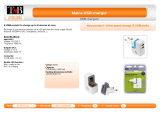
1.4 Quick Tour of the Notebook
Please take a moment to become familiar with the location and purpose of every control, the
LED status panel, connectors and ports, which are illustrated in this section. It is
recommended to first go through the User Guide of the notebook, which is shipped together
with the notebook for information on how to operate its features.
1.4.1 Inside the Notebook
To open the LCD cover of the notebook, find the cover latch located at the front center of the
LCD cover. Push the latch to the right to release and tilt the LCD cover up. Inside, you will
see the LCD display panel, keyboard, touch pad, status LED, and power switch.
n
Color LCD Panel
o
Easy Button
p
Power On /
Resume Button
q
Touch Pad Pointing
Device
r
Power Status LED
Indicator
s
Status LED
Indicator
t
Keyboard
u
Integrated Microphone
Figure 1-2 Inside the Notebook
Color LCD Display Panel
The notebook comes with several LCD option sizes at 15” SXGA+ (1400x1050) or 14.1”
XGA (1024x768) active-matrix TFT color liquid crystal display (LCD). You can adjust and
tilt (up to 180
o
) the LCD screen panel to your desired viewing position.
The notebook computer comes with a color LCD that you can adjust for a comfortable
viewing position. The LCD can be 14.1” TFT color LVDS with 1024x768 XGA (Extended
Graphics Array) resolution panels or 15” TFT color LVDS with 1400x1050 resolution. The
features of the Color LCD Display are summarized as follows:
FIC M295 / M296 Service Manual 1-7

Outline of the M295 / M296
• TFT color LVDS with 14.1" 1024x768 XGA or 15" 1400x1050 resolution panels.
• Capable of displaying 16M colors (32-bit true color) on either size panels.
• LVDS display control hot-keys allows you to adjust the brightness of the LCD.
• Simultaneous display capability for LCD and external desktop computer monitor.
• LCD display can be 14.1” or 15" TFT.
You adjust the brightness level of the LCD by pressing the display control hot-keys. You
activate the hot-keys by pressing the <Fn> key along with another function key:
• <Fn> + <F8>
Key = Increases the brightness of the LCD display
• <Fn> + <F9>
Key = Decreases the brightness of the LCD display
Keyboard Panel
− Standard QWERTY-key layout and full-sized 87 / 90 keys keyboard with
Windows hot-keys, embedded numeric keypad, hot keys, inverted “T” cursor
arrow keys, and separate page screen control keys.
− Wide extra space below the keyboard panel for your wrist or palm to sit-on
comfortably during typing. (The keypad F4, F5, F7 on the following keyboard
should no words print on it.)
n
Function Keys
o
q
Control Keys
p
Windows
Start Menu Key
r
Windows Short-cut Key
s
Cursor Control Keys
Figure 1-3 Keyboard Layout
The notebook keyboard is a little bit different from a standard desktop keyboard. Aside
from the normal alphanumeric characters and the standard keyboard function keys, the
notebook keyboard includes an embedded numeric keypad, and special function keys that
activates by pressing the <Fn> key together with another key. These special function keys
or “hot-keys” allow you to control and adjust some of the functions of the notebook like
display controls, power saving features, and others.
(1) Function Keys — These function keys, out of
<F1> through <F12>, are available on
the notebook keyboard. These keys also work together with the
<Fn> key to activate
1-8 FIC M295 / M296 Service Manual

Outline of the M295 / M296
special functions. The following function-key combinations are pre-programmed:
Hot Key Function Handler
Fn + F3 Toggle Display (LCD/CRT/Simul) BIOS Handler
Fn + F5 Display stretching BIOS Handler
Fn + F6 Speaker On/Off BIOS Handler
Fn + F8 Brightness Increase Controlled by PMU07
Fn + F9 Brightness Decrease Controlled by PMU07
Power button System Suspend to disk BIOS Handler
(2) Control keys – <Ctrl>, <Alt>, <Fn>, and <Shift> keys are controls used in
conjunction with other keys to change their functions. To use control keys, press and
hold the control key while pressing another key. For example, “Press
<Ctrl>+ <C>”
means to hold down the
<Ctrl> key and type the letter <C>.
(3) Windows keys (Windows Start Menu Key) – Use this key to activate the Start
Menu of Windows.
(4) Shortcut/Application key – provides quick access to shortcut menus. (This key acts
like a right mouse button.)
(5) Cursor Control keys – Cursor control keys let you position the cursor on the screen
where you want. On the screen, the cursor is a blinking underline, block, or vertical
bar depending on the application.
(6) Typewriter keys – Typewriter keys (also called alphanumeric keys) are used to enter
text and characters. Keys with blue print on them behave differently when combined
with control keys or the
<Fn> key.
(7) Numeric Keypad – Pressing
<NumLock> on the keyboard activates the embedded
numeric keypad numbers and functions printed in blue on top of the keys. When you
press
<NumLock> again, the keys revert to their normal functions as typewriter keys.
Figure 1-4 Embedded Numeric Keypad
Integrated Microphone
This allows you to instantly record voice annotations (normally saved as WAV files) and later
attached them to documents and presentation using the notebook integrated audio system and
application software. Since the notebook also supports full-duplex audio capabilities, you can
talk to the microphone and at the same time listen to others talk when connected to a
speakerphone modem, Internet live chat, or video conferencing.
FIC M295 / M296 Service Manual 1-9

Outline of the M295 / M296
Power Status LED Indicator
Located just on TFT LED panel assembly, you will find three LEDs for the power and battery
charge status. These LEDs are positioned to be visible even if the LCD cover is closed.
n
Power Indicator
o
Battery Charging LED
p
Mail LED
Figure 1-5 Power Status LED Indicator
1. Power Indicator – lets you know if power to the system is turned on and if system is in
Suspend-to-RAM mode. This LED is positioned so that you can see it on both sides
whether the LCD panel is opened or closed.
− Lights green when the system is powered on using the AC adapter or battery.
− Lights green blinking when in Suspend to RAM mode and critically low battery
power. We strongly recommend that users create the partition "Save to Disk" (for
Win98 only) as this will prevent your data from loss when power is critically low.
For Windows version later then Win98, please use hibernation mode instead.
2. Battery Charging LED – lights to indicate battery in charging status.
− Lights organge to indicate the battery is charging.
− Lights off to indicate the battery is fully charged or no battery installed.
3. Mail LED – Lights green to indicate that a new mail is arrived.
Status LED Panel
The Status LED Panel keeps you informed of the notebook’s current operating status. Each
LED is marked with an icon to designate a system status.
Figure 1-6 Status LED Panel Icons
Icon Represents Indicates
n
IDE Drive
Access
This LED will turn on when the system is accessing the hard
disk drive (HDD) or CD-ROM / DVD-ROM / CD-RW /Combo.
1-10 FIC M295 / M296 Service Manual

Outline of the M295 / M296
o
RF Access
This LED will turn on when the system is accessing the data
from wireless device.
p
Caps Lock
This LED will turn on when the Caps Lock key is activated.
When activated, all alphabet keys typed in will be in upper
case or in capital letters.
q
Scroll Lock
This LED will turn on when the Scroll Lock key is activated.
r
Num Lock
This LED will turn on when the Num Lock key is activated.
When activated, the embedded numeric keypad (blue print
numeric keys) will be enabled.
Easy Buttons
There are three easy buttons, two use for accessing Internet and e-mail functions instantly and
easily, the other one lets you define certain functions by yourself. Description of the easy
buttons appears in the latter part of this section.
n
Internet Button
o
E-Mail Button
p
User-Defined Button
Figure 1-7 Easy Button
− Internet Button
This technology is designed specifically for providing a very convenient way
in connecting Internet only by pressing Internet button as shown in the
graphics. For more understanding and interesting, you can refer Section 2.5
of user manual to recognize the driver installation procedures in activating
Internet button.
− E-mail Button
This is the most convenient way to access the outlook 98/2000... just by
pressing this button, you can omit several procedures in entering into Outlook
environment.
− User-Defined Button
You can define these one of buttons to activate command file (like execution
file or batch file) by yourself.
FIC M295 / M296 Service Manual 1-11

Outline of the M295 / M296
Power Button
Press the Power button either to power on or power off the system. The Power button is also a
“Smart” switch, meaning that it recognizes when the system is in Suspend mode. If in
Suspend mode, pressing the Power button will bring it out of Suspend mode and resume to
the system’s last state. You can set the function of power button from the power management
setting in Windows Control Panel. Always check the Power LED after pressing the power
button to know the power status of the notebook.
o If you are unable to power off the system, use the power override function. Press the
power button and hold it in place for four seconds. The system will then power off.
Touch Pad Pointing Device
Built in just below the keyboard panel is the glide pad pointing device. The left and right
select buttons of the glide pad is found below the glide pad surface. The left select button is
configured (by default) as the left button you normally click on the left button of your mouse,
while the right select key is configured as the right mouse button. The scroll button makes it
easy to browse upwards or downwards in the software screen.
To move cursor, place your finger lightly on the glide pad and move in the desired direction.
If you reach the end of the pad, lift your finger and place it back down on the other side.
The glide pad is compatible with the standard PS/2 mouse and can be activated using the
normal DOS or Windows PS/2 mouse driver. You can also disable the glide pad in the BIOS
Setup program.
o You can execute a left button click function by simply tapping on the glide pad
surface once. Refer to the User Guide of the notebook for more information.
1-12 FIC M295 / M296 Service Manual

Outline of the M295 / M296
1.4.2 Front Side of the Notebook
n
Built-in Stereo
Speakers
o
Rewind Button
p
Forward Button
q
Stop Button
r
Play Button
s
Cover Switch
Figure 1-8 Front Side of the Notebook
Woofer
These speakers produce heavy bass voice output for music listening.
Built-in Stereo Speakers
At the front left and right sides of the base unit are two built-in stereo mini speakers with
sound boxes. The speakers are controlled by the audio controller of the notebook and
activated by installing the audio driver. For adjusting the volume of the speakers, you can use
the volume control program under Microsoft OS or by adjusting the thumb-wheel volume
knob also found on the right side of the notebook.
Lock ON/OFF Switch
Push the switch to left side to lock the status of your Audio DJ. If you lock this switch when
the music is playing, the music will continue to play no matter what button is pressed. Audio
DJ will not allow it to activate. The function of this switch is to prevent you from touching
any button accidentally.
Push the switch to right side can turn on or turn off the power of the Audio DJ.
Remind Button
Press the button for reverting to previous music. Press and hold this button to fast rewind the
audio CD.
Cover Switch
The Cover Switch is found inside the notebook assembly just underneath the latch opening
where you insert the LCD cover hook. Whenever the LCD cover is closed, it activates the
Suspend mode or shut down the computer. The action can be set on Power Option of
Windows Control Panel.
o When Suspend-to-RAM mode is activated, make sure not to leave the system for a
long period when running at battery mode. The battery will continue to drain some
power even in Suspend mode. It is better to save all files and shutdown the power
instead or run Suspend-to-Disk mode.
Audio-DJ Display
The display shows the number of the music currently playing.
FIC M295 / M296 Service Manual 1-13

Outline of the M295 / M296
Forward Button
Press the button for playing the next music. Press and hold this button to fast forward the
audio CD
Stop Button
Press the button to stop the music.
Play Button
Press the button to starting to play music
o The function of Audio DJ can be workable either in Windows system or operate it
without powering on the computer. For execute this function, you should first install
the EZ system driver. Please refer to Section 5 of Chapter 2 of user manual for
installation procedures. However, if your OS is Windows 98, you should download
and install the "Windows Media Player 7" from Microsoft's Website to activate this
function.
1.4.3 The Right Side of the Notebook
n
Blue Tooth LED
o
Air-Outlet Vent
p
Volume Control
q
IR Port
r
Microphone Jack
s
Headphone Jack
t
Air Inhalant
u
USB Port
v
PS/2 Port
Figure 1-9 Right Side of the Notebook
Blue Tooth LED
The LED is light when you activate with the Bluetooth function. (BTO option only)
Air-Outlet Vent
Emits the heat out of your computer and keeps it within operating temperature.
Volume Control
Allows you to control the speaker volume.
IR Port
Wireless data transfer of files between your notebook computer and an IR-equipped device or
notebook computer. You can also print to an IR-equipped printer without using cables. The
SIR mode provides up to 115.2Kbps of data transfer rate.
1-14 FIC M295 / M296 Service Manual

Outline of the M295 / M296
Audio Port
There are Microphone jack, and Headphone jack which are described as follows:
• Microphone Jack
Allows you to connect an external microphone for monophonic sound recording directly
into your notebook computer. Plugging in an external microphone disables the built-in
microphone.
• Headphone Jack
Lets you plug in a stereo headphone, powered speakers, or earphone set with 1/8 inch plug
for personal listening.
Air Inhalant
Inhale the air into your computer to keep it within operating temperature.
USB Port
The Universal Serial Bus (USB) port allows you to connect up to 127 USB-equipped
peripheral devices (for example, printers, scanners and so on) to your notebook computer.
1.4.4 The Left Side of the Notebook
n
Locking Device
Keyhole
o
CD-ROM, DVD-ROM,
CD-RW/DVD Combo
p
USB Port
q
PC Card Slots
Figure 1-10 Left Side of the Notebook
Locking Device Keyhole
This latch allows you to attach a Kensington security lock or other compatible lock for
securing the notebook from theft. It is found on the left side of the notebook.
CD-ROM, DVD-ROM, CD-RW or Combo Drive
The notebook comes with a standard 24X+ speed ATAPI IDE CD-ROM drive that supports
all major CD formats like CD-R, Photo CD, and Video CD. The drive utilizes a pop-out tray
loading mechanism and supports bootable CD by setting the BIOS Setup program. The
notebook also comes with the 8X+ speed DVD-ROM drive, 8X+ speed CD-RW or CD-
RW/DVD combo drive options.
USB Port
The Universal Serial Bus (USB) port allows you to connect up to 127 USB-equipped
peripheral devices (for example, printers, scanners and so on) to your notebook computer.
FIC M295 / M296 Service Manual 1-15

Outline of the M295 / M296
PC Card Slot
The PCMCIA slot compartment houses one-card slots that support one PCMCIA Type II
cards. The notebook uses a CardBus PCMCIA controller that supports 5V and 3V 32-bit
CardBus and 16-bit PC cards. The PCMCIA slot compartment comes with sliding dummy
plastic with protection. Before you can directly insert the PC card, please remove it first.
To remove the inserted PC card, slightly push the button found on the right side of the PC slot
to release the eject button. Then push it again to release the Dummy Plastic Device. When the
PC card has moved out a space out of the slot, hold the edges of the card and slowly slide it
out.
o For full functionality of PC cards, always ask for the latest driver from your PCMCIA
card dealer or download it from their Internet website.
o For network PC cards, you need first to stop the device under the PC Card
properties of Windows Control Panel. Otherwise, this may cause system hang or
system fatal error. Please use the LAN port of this notebook instead of using other
network PC card.
1-16 FIC M295 / M296 Service Manual
/