Ames Fire & Waterworks 1000SS-DCV 8 Installation guide

Type
Installation guide
RP/IS-A-1000SS
1000SS
Installation, Maintenance, & Repair
Series 1000SS
Detector Check Valve Assemblies
Sizes: 4" – 10" (100 – 250mm)**
NOTICE
For Australia and New Zealand, line strainers should be installed
between the upstream shutoff valve and the inlet of the backflow
preventer.
Testing
For field testing procedure, refer to Ames installation sheets
IS-A-ATG-1 found on www.amesfirewater.com.
For other repair kits and service parts, refer to our Backflow
Prevention Products Repair Kits & Service Parts price list
PL-A-RP-BPD found on www.amesfirewater.com.
For technical assistance, contact your local Ames representative.
WARNING
!
Read this Manual BEFORE using this equipment.
Failure to read and follow all safety and use information can
result in death, serious personal injury, property damage, or
damage to the equipment.
Keep this Manual for future reference.
You are required to consult the local building and plumbing
codes prior to installation. If the information in this manual
is not consistent with local building or plumbing codes,
the local codes should be followed. Inquire with governing
authorities for additional local requirements.
WARNING
!
Need for Periodic Inspection/Maintenance: This product must
be tested periodically in compliance with local codes, but at least
once per year or more as service conditions warrant. If installed on
a fire suppression system, all mechanical checks, such as alarms
and backflow preventers, should be flow tested and inspected in
accordance with NFPA 13 and/or NFPA 25. All products must be
retested once maintenance has been performed. Corrosive water
conditions, and/or unauthorized adjustments or repair could render
the product ineffective for the service intended. Regular checking
and cleaning of the product’s internal components helps assure
maximum life and proper product function.
WARNING
!
** Metric Dimensions are nominal pipe diameter. This product is
produced with ASME/ANSI flanged end connections.
www.amesfirewater.com
A Watts Water Technologies Company
2
NOTICE
A. The installation and maintenance of any Ames Detector Check
Valve should be performed by a qualified licensed technician.
Failure to do so may result in a malfunctioning assembly. All
instructions should be read thoroughly by the technician before
installation or performing any maintenance on the assembly.
B. Before installing an Ames Detector Check Valve, flush the lines
thoroughly to remove all debris, chips and other foreign objects.
Failure to do so may make the assembly inoperable.
C. Allow sufficient clearance around the installed assembly to conduct
testing, servicing and inspection. Allow a minimum of 12” from the
flood level to the bottom of the assembly.
Installation Instructions
WARNING
!
Depressurize valve before servicing.
Removing Cam-Check
Place yourself so that the water flow through the valve is left to
right.
1. Shut down water system by closing two gate valves and lock out
system if possible. Slowly open bleed port to relieve internal pressure.
After pressure is relieved, loosen bolts on groove coupler and remove
groove coupler and copper plate from valve body.
2. Unscrew (counterclockwise as viewed through the port facing the
check) the Cam-Check. Insert the two grooved coupler bolts into
the holes in the face of the seat. Be sure that the pins or bolts are
installed with one on each side of the cam bar as shown. Insert a long
screwdriver or pry bar between opposing pins and loosen the check
counterclockwise) until it comes free to turn by hand. Finish unscrew-
ing the Cam-Check by hand using the support ears for the clapper
and cam bar to turn the check. (See Fig 1A)
3. Lift the Check straight up and out of the port access hole.
Cam-Check Removal
4" and 6" (100 and 150mm)**
Cam-Check Installation
4" and 6" (100 and 150mm)**
Install the Cam-Check
Prior to installing the Cam-Check, ensure that all threads are clean
and free of debris, grit, or other particles. Thoroughly clean O-rings
grooves and lubricate O-rings with an FDA approved lubricant.
1. Insert the Cam-Check through the cover port with the clapper
facing down. Align the threads of the Cam-Check with the
threads in the body and start to thread the Check in by hand
- using the ears which extend from the seat ring to turn the
check assembly. DO NOT use the clapper or the cam bar to
turn the check assembly.
2.
Tighten the Cam-Check. Insert grooved coupler bolts into
the holes in the face of the seat (or use the bolts from the lid
groove coupler). Be sure that the pins or bolts are installed
with one on each side of the cam bar. Insert a long screw
driver or pry bar between opposing pins and tighten the check
(clockwise as viewed through the port facing the check) until
it comes to a solid stop. The back the check out about 15
degrees or from the 1:00 position to the 12:00 position. (See
Fig 1B).
START UP: After re-installation of the cover plate and groove
coupler — the downstream shutoff valve should be closed. Open
upstream gate slowly, fill the valve and bleed the air through bleed
port. When valve is filled, open the downstream shut off slowly.
Failure to bleed air from assembly may cause water hammer or
shock damage to the water system.
Figure 1A
Figure 1B
3
Repair Parts
#1 Cam-Check
Figure 3
Figure 2
Cam bar
Cam-Check Disassembly
4" and 6" (100 and 150mm)**
Please use caution when disassembling cam-check.
WARNING
!
You may replace this item as an assembly.
Figure 4
Using a thin rod or screwdriver, lift the cambar up so that the
clapper is free to swing upwards away from the seat.
Figure 5
Using your free hand, swing the clapper open until the roller is
almost to the free end of the cambar. Align the maintenance
lockout holes in the cambar and the hinge arms.
Secure the check assembly in the maintenance position by
inserting a rod or thin screwdriver through the lock-out holes.
Figure 6
Remove 1 c-clip from the center pivot pin. Withdraw the
centerpivot pin from the clapper and the hinge arms. Remove the
clapper assembly from the check assembly module.
Figure 4 Figure 5 Figure 6
1st Cam-Check O-ring (removable)
Cam-Check
Assembly
Cam-Check O-ring
(removable)
Groove Coupler
Groove Coupler Gasket
Cover Plate
Clapper Assembly (removable)
Pivot Arm Pin (removable) 2 c-clips
Removal & Replacement
of Knuckle Joint Assembly
(Internal Closing Assembly)
1. Shut down water system and lock out if possible.
2. Loosen vent screw in lid slowly to ensure system pressure has
been relieved.
3. Loosen and remove all inspection port bolts and remove
lid and gasket from valve.
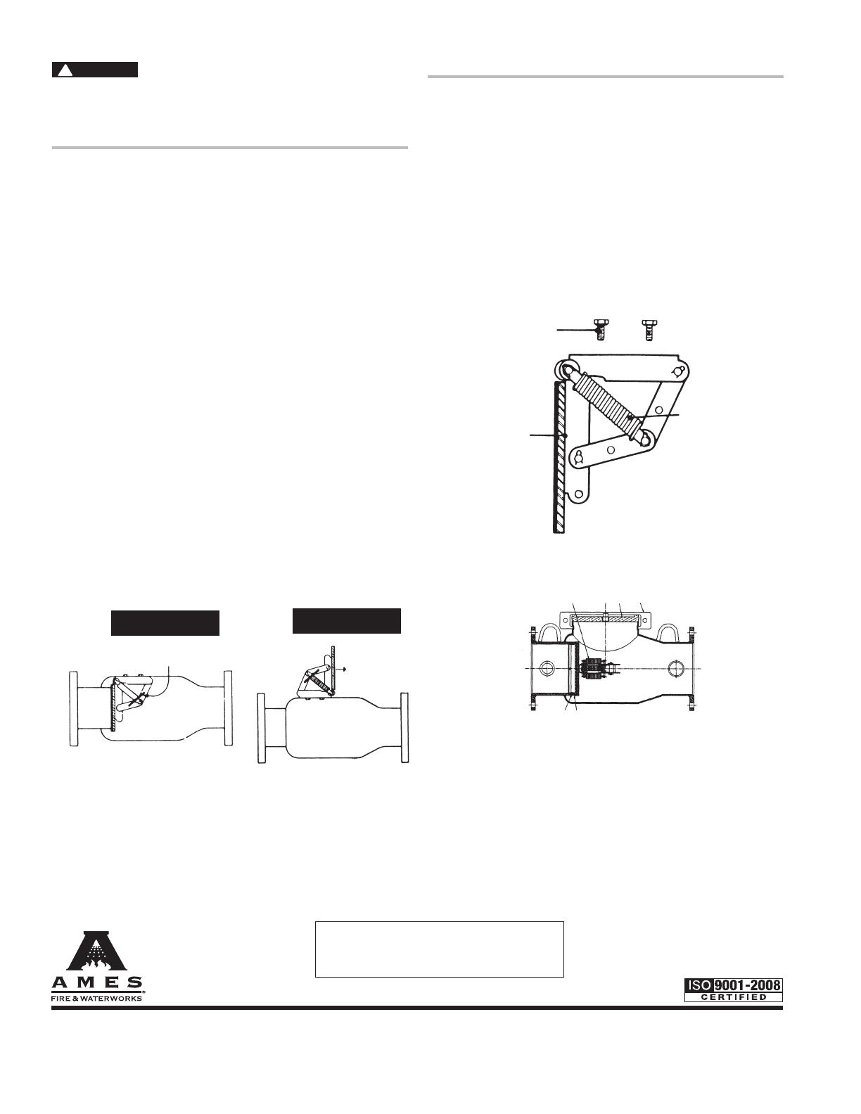
4. Install proper size clapper retainer clip (see Figure 1).
Be sure clip is pushed to within
1
2” of linkage.
5. Loosen equally the two knuckle joint mounting bolts, until as-
sembly is free. As bolts are loosened, linkage will release slightly
and lock clapper retainer clip in place.
6. Remove knuckle joint from body assuring clapper retainer clip is
not disturbed, as preloaded knuckle joint springs have consider-
able tension in this position.
7. Bolt the knuckle joint to the outside of the body using the new
3
8
bolts supplied with the new knuckle joint (see Figure 2).
8. Push on clapper plate to release clapper retainer clip, remove
and slowly release tension on clapper. Unbolt knuckle joint as-
sembly from outside of body.
9. Bolt replacement knuckle joint assembly to body.
10. Push on clapper plate to extend springs and install clapper
retainer clip, making sure springs are seated on pins. Unbolt
knuckle joint assembly from body bolt hole.
11. Insert two new
3
8” mounting bolts and washers through mount-
ing holes in body. Position knuckle joint in place inside body,
and finger tighten both bolts.
12. Torque knuckle joint mounting bolts to 60 inch-pounds. Re-
move clapper retainer clip.
13. Replace lid and new gasket.
Repair Parts
2
Knuckle Joint Assembly
1
4
3
Housing Half Section
1 8 9
7
6
WARNING
!
Depressurize valve before servicing.
Item # Description
1.
Knuckle Joint Assembly (Complete Unit)
2.
Clapper Plate With Attached Link (not shown)
3.
Springs
4.
3
/8" Stainless Steel Bolts
5.
Washer (not shown)
6.
Bronze Seat (Replaceable in Line)
7.
Seat O-Ring
8.
Cover Plate
9.
Groove Coupler
10.
Clapper Retainer Clip (Diagram 1)
RP/IS-A-1000SS 1329 EDP# 7016818 © 2013 Ames Fire & Waterworks
www.amesfirewater.com
A Watts Water Technologies Company
USA: Backflow- Tel: (916) 928-0123 Fax: (916) 928-9333
Control Valves- Tel: (713) 943-0688 Fax: (713) 944-9445
Canada: Tel: (905) 332-4090 Fax: (905) 332-7068
Limited Warranty: Ames Fire & Waterworks (the “Company”) warrants each product to be free from defects in material and workmanship under normal usage for a period of one year from the date
of original shipment. In the event of such defects within the warranty period, the Company will, at its option, replace or recondition the product without charge.
THE WARRANTY SET FORTH HEREIN IS GIVEN EXPRESSLY AND IS THE ONLY WARRANTY GIVEN BY THE COMPANY WITH RESPECT TO THE PRODUCT. THE COMPANY MAKES NO OTHER
WARRANTIES, EXPRESS OR IMPLIED. THE COMPANY HEREBY SPECIFICALLY DISCLAIMS ALL OTHER WARRANTIES, EXPRESS OR IMPLIED, INCLUDING BUT NOT LIMITED TO THE IMPLIED
WARRANTIES OF MERCHANTABILITY AND FITNESS FOR A PARTICULAR PURPOSE.
The remedy described in the first paragraph of this warranty shall constitute the sole and exclusive remedy for breach of warranty, and the Company shall not be responsible for any incidental, special
or consequential damages, including without limitation, lost profits or the cost of repairing or replacing other property which is damaged if this product does not work properly, other costs resulting
from labor charges, delays, vandalism, negligence, fouling caused by foreign material, damage from adverse water conditions, chemical, or any other circumstances over which the Company has no
control. This warranty shall be invalidated by any abuse, misuse, misapplication, improper installation or improper maintenance or alteration of the product.
Some States do not allow limitations on how long an implied warranty lasts, and some States do not allow the exclusion or limitation of incidental or consequential damages. Therefore the above
limitations may not apply to you. This Limited Warranty gives you specific legal rights, and you may have other rights that vary from State to State. You should consult applicable state laws to
determine your rights. SO FAR AS IS CONSISTENT WITH APPLICABLE STATE LAW, ANY IMPLIED WARRANTIES THAT MAY NOT BE DISCLAIMED, INCLUDING THE IMPLIED WARRANTIES OF
MERCHANTABILITY AND FITNESS FOR A PARTICULAR PURPOSE, ARE LIMITED IN DURATION TO ONE YEAR FROM THE DATE OF ORIGINAL SHIPMENT.
WARNING: This product contains chemicals known to the
State of California to cause cancer and birth defects or
other reproductive harm.
For more information: www.watts.com/prop65
Figure 1
Figure 2
Claper Retainer
Direction of
Flow
  • Page 1 1
  • Page 2 2
  • Page 3 3
  • Page 4 4

Ames Fire & Waterworks 1000SS-DCV 8 Installation guide

Type
Installation guide

Ask a question and I''ll find the answer in the document

Finding information in a document is now easier with AI