Page is loading ...

SAX772PUSAX762PU
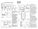
Installation and Assembly:
Universal Articulating Arm Wall Mount for Flat Panel Displays
ISSUED: 01-25-12 SHEET #: 095-9370-5 02-22-13
2300 White Oak Circle • Aurora, Il 60502 • (800) 865-2112 • Fax: (800) 359-6500 • www.peerless-av.com
Model Maximum UL Load Capacity Screen Size Range
SAX762PU 110 lbs (49.9 kg) 40" - 63" (102 - 160cm)
SAX772PU 135 lbs (61.2 kg) 50" - 71" (127 - 180cm)

2 of 41
ISSUED: 01-25-12 SHEET #: 095-9370-5 02-22-13
Note: Read entire instruction sheet before you start installation and assembly.
Table of Contents
Parts List.............................................................................................................................................................................3, 4
Installation to Wood Stud ........................................................................................................................................................5
Installation to Solid Concrete or Cinder Block ........................................................................................................................6
Installing Adapter Brackets to Display ....................................................................................................................................7
Mounting Flat Panel Display ...................................................................................................................................................9
For VESA 200 x 200 mounting pattern ...................................................................................................................................9
Adjustment of Flat Panel Dispaly..........................................................................................................................................10
Cable Management ..............................................................................................................................................................12
Tools Needed for Assembly
• stud fi nder ("edge to edge" stud fi nder is recommended)
• phillips screwdriver
• 3/16" (5mm) drill bit for wood studs
• 3/8" (10mm) drill bit for concrete and cinder block
• level
• Do not begin to install your Peerless product until you have read and understood the instructions and warnings
contained in this Installation Sheet. If you have any questions regarding any of the instructions or warnings, for US
customers please call Peerless customer care at 1-800-865-2112, for all international customers, please contact
your local distributor.
• This product should only be installed by someone of good mechanical aptitude, has experience with basic building
construction, and fully understands these instructions.
• Make sure that the supporting surface will safely support the combined load of the equipment and all attached
hardware and components.
• Never exceed the Maximum Load Capacity. See page one.
• If mounting to wood wall studs, make sure that mounting screws are anchored into the center of the studs. Use of
an "edge to edge" stud fi nder is highly recommended.
• Always use an assistant or mechanical lifting equipment to safely lift and position equipment.
• Tighten screws fi rmly, but do not overtighten. Overtightening can damage the items, greatly reducing their holding
power.
• This product is intended for indoor use only. Use of this product outdoors could lead to product failure and personal
injury.
• This product was designed to be installed on the following wall construction only;
WALL CONSTRUCTION HARDWARE REQUIRED
• Wood Stud Included
• Wood Beam Included
• Solid Concrete Included
• Cinder Block Included
• Brick Contact Qualifi ed Professional (not evaluated by UL)
• Other or unsure? Contact Qualifi ed Professional
WARNING

3 of 41
ISSUED: 01-25-12 SHEET #: 095-9370-5 02-22-13
IH
K
L
CD
Parts may appear slightly different than illustrated.
Before you begin, make sure all parts shown are included with your product.
A
A
or
SAX762PU
SAX772PU
E
G
J M
F
N
SAX762PU
SAX772PU
Description Qty. Part # Qty. Part #
A
wall arm assembly 1 095-1829 1 095-1830
B adapter bracket 2 095-1787 2 095-1792
C wood screw 4 520-1243 4 520-1243
D concrete anchor 4 590-0321 4 590-0321
E portrait lock clip 4 095-1734 4 095-1734
F
wall plate covers
2
095-1747 2 095-1747
G
cable ties
8
590-1168 16 590-1168
H M5 x 13mm self tapping screws 4 520-1616 4 520-1616
I M5 flat washers 4 540-1040 4 540-1040
J 5 mm allen wrench 1 560-9640 1 560-9640
K 6.75" cable cover 2 095-1818 4 095-1818
L
4.25" cable cover
2
095-1817 4 095-1817
M
5/32 allen wrench
1 560-9646 1 560-9646
N
support plate
4 095-1731 4 095-1731
Parts List
BB
or
SAX772PU
SAX762PU

4 of 41
ISSUED: 01-25-12 SHEET #: 095-9370-5 02-22-13
Non-Security Adapter Bracket Fasteners
I.D. .34" (4)
(540-1059)
multi-washer (4)
(580-1398)
M5 x 12mm (4)
(520-1027)
M5 x 25mm (4)
(520-9543)
M6 x 12mm (4)
(520-1128)
M6 x 25mm (4)
(520-1208)
M8 x 25mm (4)
(520-1031)
NOTE: If mounting wall arm (A) to wood stud walls, slots on wall plate must align to wood studs.
Determine desired location of display center detailed in step 2.
Measure the distance from the center of wall arm (A) to desired display center. Loosen four phillips screws and
slide wall arm up to 4.5" left or right to align to desired display center. Retighten screws.
Do not adjust arm while display is attached.
Skip to page 6 for Concrete and Cinder Block Installation.
1
Optional Horizontal Adjustment of Wall Arm on Wall Plate
PHILLIPS SCREWS
FRONT PLATE NOT
SHOWN FOR CLARITY
WALL PLATE
WALL ARM
SLOT
SLOT
M8 x 12mm (4)
(520-9571)

5 of 41
ISSUED: 01-25-12 SHEET #: 095-9370-5 02-22-13
Using a stud fi nder, locate and mark the edges of the wood stud. Use a level to draw a vertical line down the center
of the stud and mark the desired display center. Use wall plate template (wall arm) to mark center of holes along
the vertical line. The top mounting hole should be 8.55" (217mm) above the desired display center as shown in
fi gure 2.1. Drill four 3/16" (5mm) dia. pilot holes to a depth of 3" (76mm). Attach wall arm (A) to wall using four wood
screws (C) and four support plates (N) as shown in fi g. 2.2.
Installation to Wood Stud Wall
2
• Installer must verify that the supporting surface will safely support the combined load of the equipment and all
attached hardware and components.
• Tighten wood screws so that wall plate is fi rmly attached, but do not overtighten. Overtightening can damage the
screws, greatly reducing their holding power.
• Never tighten in excess of 80 in. • lb (9 N.M.).
• Make sure that mounting screws are anchored into the center of the stud. The use of an "edge to edge" stud fi nder
is highly recommended.
• Hardware provided is for attachment of mount through standard thickness drywall or plaster into wood studs.
Installers are responsible to provide hardware for other types of mounting situations (not evaluated by UL).
DC = DISPLAY CENTER
WOOD STUD
C
N
A
WOOD STUD
DC
fi g. 2.1
fi g. 2.2
WARNING
8.55"
(217mm)

6 of 41
ISSUED: 01-25-12 SHEET #: 095-9370-5 02-22-13
Installation to Solid Concrete or Cinder Block
Mark the desired display center and use wall plate
template (wall plate) to mark mounting holes. The
top mounting hole should be 8.55" (217mm) above
the desired display center as shown in fi gure 2.1
on page 5. Drill four 3/8" (10mm) dia. pilot holes to
a depth of 3" (76mm). Insert anchors (D) into holes
fl ush with wall as shown (right). Place wall arm
over anchors and secure with 5/16 x 3" screws (C)
and four support plates (N). Level, then tighten all
fasteners.
D
2
A
C
N
• When installing Peerless wall mounts on cinder block, verify that you have a minimum of 1-3/8" (35mm) of actual
concrete thickness in the hole to be used for the concrete anchors. Do not drill into mortar joints! Be sure to mount
in a solid part of the block, generally 1" (25mm) minimum from the side of the block. Cinder block must meet ASTM
C-90 specifi cations. It is suggested that a standard electric drill on slow setting is used to drill the hole instead of a
hammer drill to avoid breaking out the back of the hole when entering a void or cavity.
• Concrete must be 2000 psi density minimum. Lighter density concrete may not hold concrete anchor.
• Make sure that the supporting surface will safely support the combined load of the equipment and all attached
hardware and components.
• Tighten screws so that wall plate is fi rmly attached,
but do not overtighten. Overtightening can damage
screws, greatly reducing their holding power.
• Never tighten in excess of 80 in. • lb (9 N.M.).
• Always attach concrete expansion anchors directly
to load-bearing concrete.
• Never attach concrete expansion anchors to
concrete covered with plaster, drywall, or other
fi nishing material. If mounting to concrete surfaces
covered with a fi nishing surface is unavoidable (not
evaluated by UL), the fi nishing surface must be
counterbored as shown below. Be sure concrete
anchors do not pull away from concrete when
tightening screws. If plaster/drywall is thicker than
5/8" (16mm), custom fasteners must be supplied by
installer (not evaluated by UL).
WARNING
SOLID CONCRETE
CINDER BLOCK
WARNING
CUTAWAY VIEW
INCORRECT CORRECT
wall
plate
wall
plate
plaster/
dry wall
plaster/
dry wall
concrete
concrete
1
3
2
D
Drill holes and insert anchors (D).
Place plate (A) over anchors (D) and secure with screws (C).
Tighten all fasteners.
A
D
C
concrete
surface

7 of 41
ISSUED: 01-25-12 SHEET #: 095-9370-5 02-22-13
For VESA 200 x 200 mounting pattern, skip to step 5 on page 9.
To prevent scratching the display, set a cloth on a fl at, level surface that will support the weight of the display.
Place display face side down. If display has knobs on the back, remove them to allow the adapter brackets to be
attached. Place adapter brackets (B) on back of display, align to holes, and center on back of display as shown
below. Attach the adapter brackets to the back of the display using the appropriate combination of screws,
multi-washers, and spacers as shown in steps 3-1 or 3-2.
NOTE: Top and bottom mounting holes on display must be used for attaching brackets.
NOTE: Verify that all holes are properly aligned, and then tighten screws using a phillips screwdriver.
NOTE: For fl at back displays proceed to step 3-1. For bump-out or recessed back display skip to step 3-2.
NOTE: "X" dimensions should be equal.
CENTER BRACKETS
VERTICALLY ON BACK
OF DISPLAY
X
X
3
NOTES:
• The number of fasteners used will vary, depending
upon the type of display.
• Multi-washers and spacers may not be used,
depending upon the type of display.
• Use the corresponding hole in the multi-washer that
matches your screw size as shown.
MEDIUM HOLE FOR M5 SCREWS
SMALL HOLE FOR M4 SCREWS
LARGE HOLE FOR M6 SCREWS
MULTI-WASHER
Installing Adapter Brackets
• Tighten screws so adapter brackets are fi rmly attached. Do not tighten with excessive force. Overtightening can
cause stress damage to screws, greatly reducing their holding power and possibly causing screw heads to become
detached. Tighten to 40 in. • lb (4.5 N.M.) maximum torque.
• If screws don't get three complete turns in the display inserts or if screws bottom out and bracket is still not tightly
secured, damage may occur to display or product may fail.
WARNING
B

8 of 41
ISSUED: 01-25-12 SHEET #: 095-9370-5 02-22-13
If you have any questions, please call Peerless customer care at 1-800-865-2112.
If you have any questions, please call Peerless customer care at 1-800-865-2112.
Begin with the shortest length screw, hand thread through multi-washer and adapter bracket into display as shown
below. Screw must make at least three full turns into the mounting hole and fi t snug into place. Do not overtighten.
If screw cannot make three full turns into the display, select a longer length screw from the baffl ed fastener pack.
Repeat for remaining mounting holes, level brackets and tighten screws.
NOTE: Spacers may not be used, depending upon the type of display.
Begin with longer length screw, hand thread through multi-washer, adapter bracket and spacer in that order into
display as shown below. Screw must make at least three full turns into the mounting hole and fi t snug into place.
Do not overtighten. If screw cannot make three full turns into the display, select a longer length screw from the
baffl ed fastener pack. Repeat for remaining mounting holes, level brackets and tighten screws.
For Flat Back Display
For Bump-out or Recessed Back Display
3-1
3-2
DISPLAY
DISPLAY
MULTI-WASHER
MULTI-WASHER
SCREW
SCREW
fi g. 3.2
fi g. 3.1
SPACER
ADAPTER BRACKET (B)
ADAPTER BRACKET (B)

9 of 41
ISSUED: 01-25-12 SHEET #: 095-9370-5 02-22-13
fi g. 4.1
CROSS SECTION
DETAIL 1
Mounting Display: Slowly hook adapter brackets
(B) onto top rail of front plate wall arm (A) then
swing display down as shown in fi gure 4.1. Adapter
bracket hooks must fully engage adapter plate as
shown in detail 1. Using allen wrench (M), turn
safety/security screws on adapter brackets (B)
clockwise till screw tip securely contacts adapter
plate as shown in cross section.
Removing Display: To remove display from mount,
loosen safety/security screws, swing display away
from mount, and lift display off of mount.
4
• Always use an assistant or mechanical lifting
equipment to safely lift and position the fl at panel
display.
• Do not tighten screws with excessive force.
Overtightening can cause damage to mount. Tighten
screws to 40 in. • lb (4.5 N.M.) maximum torque.
• Be careful not to pinch fi ngers when pushing display
from the bottom.
WARNING
B
B
A
A
A
SAFETY/
SECURITY
SCREW
For VESA 200 x 200 Mounting Pattern
Remove eight M6 x 8mm screws and unhook top and bottom rails from front plate.
5
M6 X 8MM
SCREWS
FRONT PLATE
BOTTOM RAIL
TOP RAIL
TOP RAIL
BOTTOM RAIL

10 of 41
ISSUED: 01-25-12 SHEET #: 095-9370-5 02-22-13
Insert two M8 x 16mm screws into bottom holes of
adapter plate as shown, then tighten all fasteners.
Insert two M8 x 16mm screws into top two mounting
holes of display, leaving approximately 1/4" (6mm)
of exposed thread. Hook screws onto keyslots of
front plate as shown.
5-25-1
FRONT PLATE
Tension Adjustment of Ratchet Handle: Adjust
tension of tilt assembly by rotating ratchet handle.
NOTE: If obstruction prevents ratchet handle from
rotating, pull handle out while turning will allow
handle to reposition without tightening. Release and
turn handle to tighten or loosen.
Tilt Adjustment: Adjust ratchet handle on side of
mount to desired tension to enable tilt adjustment
and balance your display size and weight. Push
or pull from top or bottom of display to adjust tilt
as shown. The tilt can be adjusted to a maximum
of 15° forward or 5° backward. Retighten ratchet
handle.
Vertical Height Adjustment: Loosen or tighten
vertical adjustment screw using 5mm allen wrench
(J) to raise or lower position of fl at panel display +/-
.70".
6
RATCHET HANDLE
• Do not tighten screws with excessive force.
• Be careful not to pinch fi ngers when opening and
closing mount from the wall.
CAUTION
VERTICAL
ADJUSTMENT SCREW
Adjustment of Flat Panel Display
M8 X 16MM SCREWS
M8 X 16MM SCREWS

11 of 41
ISSUED: 01-25-12 SHEET #: 095-9370-5 02-22-13
Remove button socket head screw with round plate
as shown in detail 3.
Rotate display to desired position, then reinstall
socket head screw with round plate to lock down.
8-1
FRONT OF
DISPLAY
Install four portrait lock clips (E) to top and bottom rails with four M5 x 13mm self tapping screws (H) and four fl at
washers (I) as shown in detail 2. Tighten using allen wrench (M). Portrait lock clips must fi t snug against inside of
adapter brackets (B) as shown in fi gure 7.1.
7
• Portrait lock clips (E) must be securely installed to top and bottom rails against inside of adapter brackets (B).
Failure to place lock clips in correct location may cause injury.
WARNING
8
Optional Orientation Adjustment
DETAIL 3
BUTTON SOCKET HEAD SCREW
B
E
I
H
DETAIL 2
RAILS
E
E
B
fi g. 7.1
REAR OF
DISPLAY
BOTTOM RAIL
TOP RAIL

12 of 41
ISSUED: 01-25-12 SHEET #: 095-9370-5 02-22-13
Cable Management
NOTE: Make sure cables have enough slack to allow full movement of the arm.
Run power cable through top or bottom of wall arm (A) and signal cable(s) through other side of arm in order to
avoid interference with the signal. Secure cables into place with two sets of cable covers (K, L) on each arm.
Display may have to be moved for easy access.
9
L
K
Snap wall plate covers (F) to top and bottom of wall
plate rails as shown.
10
F
WALL PLATE RAIL
L
L
CABLES

13 of 41
ISSUED: 01-25-12 SHEET #: 095-9370-5 02-22-13
If more or less tension is desired in the arm pivot points, do the following:
• To increase tension, turn socket screw clockwise with 5mm allen wrench (J). NOTE: Tighten screws to
50 in • lbs (5.6 N.m.) maximum torque.
• To reduce tension, turn socket screw counter-clockwise with 5mm allen wrench (J). NOTE: Do not turn more
than half a turn.
11
TENSION SCREWS
TENSION SCREW
• Do not remove screw or loosen screw until it is no longer engaged with the mount. Doing so may cause the display
to fall.
• If screws become loose over time, tighten screws as necessary. Tighten screws to 50 in • lbs (5.6 N.m.) maximum
torque.
WARNING
© 2013, Peerless Industries, Inc. All rights reserved.
All other brand and product names are trademarks or registered trademarks of their respective owners.
Peerless Industries, Inc.
2300 White Oak Circle
Aurora, Il 60502
www.peerless-av.com

SAX772PUSAX762PU
Instalación y montaje:
Soportes de Pared de Brazo Articulador Para Pantallas Planas
PUBLICADO: 01-25-12 HOJA #: 095-9370-5 02-22-13
2300 White Oak Circle • Aurora, Il 60502 • (800) 865-2112 • Fax: (800) 359-6500 • www.peerless-av.com
Modelo Máxima capacidad de carga para UL
Gama de Tamaño
de las Pantallas
SAX762PU 110 lbs (49.9 kg) 40" - 63" (102 - 160cm)
SAX772PU 135 lbs (61.2 kg) 50" - 71" (127 - 180cm)

SAX772PUSAX762PU
Installation et montage :
Montants muraux pour écrans plats articulés pour écrans
PUBLIÉ LE : 01-25-12 FEUILLE n
o
: 095-9370-5 02-22-13
2300 White Oak Circle • Aurora, Il 60502 • (800) 865-2112 • Fax: (800) 359-6500 • www.peerless-av.com
Modèle Capacité de Charge Maximale por UL
Plage de Dimensions
de l’écran
SAX762PU 110 lbs (49.9 kg) 40" - 63" (102 - 160cm)
SAX772PU 135 lbs (61.2 kg) 50" - 71" (127 - 180cm)

40 of 41
ISSUED: 01-25-12 SHEET #: 095-9370-5 02-22-13
© 2013 Peerless Industries, Inc.
Peerless Industries, Inc. (“Peerless”) warrants to original end-users of Peerless® products will be free from defects in material and workmanship, under normal
use, for a period of fi ve years from the date of purchase by the original end-user (but in no case longer than six years after the date of the product’s manufacture).
At its option, Peerless will repair or replace, or refund the purchase price of, any product which fails to conform with this warranty.
In no event shall the duration of any implied warranty of merchantability or fi tness for a particular purpose be longer than the period of the applicable
express warranty set forth above. Some states do not allow limitations on how long an implied warranty lasts, so the above limitation may not apply to you.
This warranty does not cover damage caused by (a) service or repairs by the customer or a person who is not authorized for such service or repairs by Peerless,
(b) the failure to utilize proper packing when returning the product, (c) incorrect installation or the failure to follow Peerless’ instructions or warnings when installing,
using or storing the product, or (d) misuse or accident, in transit or otherwise, including in cases of third party actions and force majeure.
In no event shall Peerless be liable for incidental or consequential damages or damages arising from the theft of any product, whether or not secured
by a security device which may be included with the Peerless® product. Some states do not allow the exclusion or limitation of incidental or consequential
damages, so the above limitation or exclusion may not apply to you.
This warranty is in lieu of all other warranties, expressed or implied, and is the sole remedy with respect to product defects. No dealer, distributor, installer or other
person is authorized to modify or extend this Limited Warranty or impose any obligation on Peerless in connection with the sale of any Peerless® product.
This warranty gives specifi c legal rights, and you may also have other rights which vary from state to state.
LIMITED FIVE-YEAR WARRANTY
www.peerless-av.com
Español
© 2013 Peerless Industries, Inc.
Peerless Industries, Inc. (Peerless) les garantiza a los usuarios fi nales originales de los productos Peerless® que los productos Peerless® estarán libres de
defectos de materiales o de manufactura, en condiciones de uso normal, durante un periodo de cinco (5) años a partir de la fecha en la que el usuario fi nal
original compre cualquier producto (pero, en ningún caso, durante un periodo mayor de 6 años después de la fecha de manufactura del producto). Queda a la
discreción de Peerless, reparar, reemplazar o rembolsar el precio de compra de cualquier producto que no cumpla esta garantía.
La duración de toda garantía implícita de comerciabilidad o de idoneidad para un propósito en particular no sobrepasará en caso alguno el periodo
de vigencia de la garantía explícita correspondiente indica en lo anterior. Algunos Estados no permiten que se establezcan limitaciones en relación con el
periodo de duración de una garantía implícita, de manera que es posible que la limitación expuesta en lo anterior no sea pertinente a usted.
Esta garantía no cubre daños causados por (a) trabajos de mantenimiento o de reparación hechos por el cliente o alguna persona que no esté autorizada por
Peerless para realizar dichos trabajos de mantenimiento o de reparación, (b) no empacar el producto como es debido si lo devuelve, (c) hacer una instalación
incorrecta o no seguir las instrucciones o las advertencias de Peerless al instalar, utilizar o guardar el producto o (d) el mal uso o los accidentes, en tránsito o en
otras circunstancias, incluidos los casos relacionados con las acciones de terceros o una fuerza mayor.
Peerless no tendrá responsabilidad en ningún caso de daños y perjuicios incidentales o indirectos o de daños y perjuicios que surjan por el robo de
cualquier producto, ya sea que el mismo esté o no esté asegurado con un dispositivo de seguridad que se haya incluido con el producto de Peerless®.
Algunos Estados no permiten que se excluyan o se establezcan limitaciones en relación con los daños y perjuicios incidentales o indirectos, de manera que es
posible que la limitación o la exclusión expuesta en lo anterior no sea pertinente a usted.
Esta garantía remplaza toda otra garantía, expresa o implícita, y es el único recurso en lo que respecta a los defectos del producto. Ningún concesionario,
distribuidor, instalador ni ninguna otra persona está autorizada a modifi car o extender esta Garantía Limitada ni a imponer obligación alguna a Peerless en
relación con la venta de cualquier producto de Peerless®.
Esta garantía concede derechos específi cos creados por ley y es posible que usted, además, tenga otros derechos que varían de acuerdo con el Estado donde
se encuentre.
GARANTÍA LIMITADA DE CINCO AÑOS
www.peerless-av.com
/