Page is loading ...

VAREC 3600B/3650B SERIES PRESSURE OR VACUUM RELIEF VALVES
INSTRUCTION, OPERATION AND MAINTENANCE MANUAL
© 2017 Emerson. All rights reserved.
DISCLAIMER OF WARRANTIES
The contract between Emerson Automation
Solutions (Emerson) and our customer states
Emerson entire obligation. The contents of
this instruction manual shall not become part
of or modify any prior or existing agreement,
commitment or relationship between Emerson
and our customer. There are no express or
implied warranties set out in this instruction
manual. The only warranties that apply are those
in the existing contract between Emerson and
our customer.
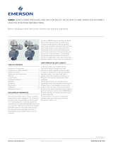
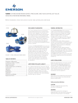
The Varec 3600B and 3650B Series pressure
or vacuum relief valves have not been tested
by Emerson under all possible operational
conditions and Emerson does not have all the
data relative to your application. The information
in this instruction manual is not all inclusive and
does not and cannot take into account all unique
situations. Consequently, you should review this
product literature in view of your application. If
you have any further questions, please contact
Emerson for assistance.
Emerson.com/FinalControl
Before installation, these instructions must be read carefully and understood.
D104513X012 19/08
LIMITATIONS OF SELLER’S LIABILITY
If it is determined that this instruction manual
created some new warranties, Emerson liability
shall be limited to repair or replacement under
the standard warranty clause. In no case
shall Emerson liability exceed that stated as
Limitations of Remedy in the contract between
Emerson and our customer
SAFETY PRECAUTIONS
Read and understand this instruction manual
before installing, operating or performing
maintenance on 3600B and 3650B Series
pressure or vacuum relief valves. Follow
all precautions and warnings noted herein
when installing, operating or performing
maintenance on this equipment.
WARNING
Relief valve must be isolated from tank pressure
before servicing. All gas must be blocked and
pressure safely vented.
Safety precaution definitions
CAUTION
Damage to equipment may result if this
precaution is disregarded.
WARNING
Direct injury to personnel or damage to
equipment which can cause injury to personnel
may result if this precaution is not followed.
GENERAL INFORMATION
The 3600B and 3650B Series pressure or
vacuum relief valves are designed to protect
low pressure storage tanks, sludge digesters
and gas holders from excessive pressure or
vacuum.
The 3600B Series vacuum relief valve is a side
mounted valve that relieves negative pressure
by inbreathing ambient air.
The 3650B Series pressure relief valve is a top
mounted valve that relieves pressure through
an enclosed outlet adapter. Product vapors may
be piped away rather than relieving
directly to
the atmosphere. This valve may also be used as a
side mounted vacuum relief valve with the intake
flange connectable to a dehydrator.
FIGURE 1. 3600B AND 3650B SERIES
TABLE OF CONTENTS
Disclaimer of Warranties �����������������������������������1
Limitations of Seller's Liability ��������������������������1
General Information �������������������������������������������1
Safety Precautions ���������������������������������������������1
Product Identification and Marking �������������������2
Construction �������������������������������������������������������2
Operation ������������������������������������������������������������4
Installation ����������������������������������������������������������5
Maintenance �������������������������������������������������������5
Calibration ����������������������������������������������������������6
Dimensions and Weight �������������������������������������7
Replacement Parts �������������������������������������������11
3600B Series
3650B Series

2
1 G c T6
2 G c T6
VAREC 3600B/3650B SERIES PRESSURE OR VACUUM RELIEF VALVES
INSTRUCTION, OPERATION AND MAINTENANCE MANUAL
CONSTRUCTION
Standard materials of construction include a cast
body and cover. Pallets are dead weight loaded
with lead or coated steel weights and include a
flexible membrane sealing insert. The pallet is
loosely guided through a center stem and pallet
guide posts.
The 'All-weather' Models 3601B and 3651B
Series include a special coating on portions
of the pallet, seat ring and guides to eliminate
ice accumulation.
TABLE 1 - 3600B SERIES CONFIGURATION
Code Type
360 Vacuum Relief Valve (Side Mounted)
Code Configuration
0B Standard
1B All Weather Type
Code Size
2 2 inches
3 3 inches
4 4 inches
6 6 inches
8 8 inches
0 10 inches
1 12 inches
Code Body/trim material
1 Aluminum/Aluminum
2 Aluminum/316 Stainless steel
3 Steel/316 Stainless steel
4 316 Stainless steel/316 Stainless steel
Code Insert material
T Fluorinated Ethylene Propylene (FEP)
B Nitrile (NBR)
V Fluorocarbon (FKM)
Code Flange Drilling
F 150# ANSI Drilling (Fractional Studs)
D PN 16 DIN Drilling (Metric Studs)
Code Flange Face
F Flat Face Flange
R Raised Face Flange (Not Available with Aluminum)
Code Gasket/o-ring material
O Standard
B Nitrile (NBR)
T Polytetrafluoroethylene (PTFE)
V Fluorocarbon (FKM)
Code Retainer/Screen Material
P Plastic
S Stainless steel
Code Vacuum Setting Ranges
02 Low
04 High
NOTE
Materials for the 3600B Series valves are as indicated by the full 14-character model number as
shown above.
PRODUCT IDENTIFICATION AND MARKING
Hazardous Locations
The 3600B/3650BSeries Pressure and Vacuum
Relief Valves (PVRVs) are available with outer
housings of Carbon steel, Stainless steel or
Aluminum as indicated.
Outer Housing of Stainless
Steel, Carbon Steel or
Coated Aluminum
Outer Housing of
Uncoated Aluminum
Nameplate
The nameplate is attached to the valve and
contains the following information.
1. Connection Size (Size)
2. Serial Number (S/N)
3. Model Number (P/N) per Construction Table
4. Pressure Setting and Air Flow (Not
applicable for Model3600B. Pressure and
Vacuum settings are mutually exclusive.)
5. Vacuum Setting and Air Flow (Pressure and
Vacuum settings are mutually exclusive.)
6. Notified Body Number

3
TABLE 2 - 3650B SERIES CONFIGURATION
Code Type
365 Pressure or Vacuum Relief Valve (In-Line)
Code Configuration
0B Standard
1B All Weather Type
Code Size
2 2 inches
3 3 inches
4 4 inches
6 6 inches
8 8 inches
0 10 inches
1 12 inches
Code Body/trim material
1 Aluminum/Aluminum
2 Aluminum/316 Stainless steel
3 Steel/316 Stainless steel
4 316 Stainless steel/316 Stainless steel
Code Insert material
T FEP
B Nitrile (NBR)
V Fluorocarbon (FKM)
Code Flange Drilling
F 150# ANSI Drilling (Fractional Studs)
D PN 16 DIN Drilling (Metric Studs)
Code Flange Face
F Flat Face Flange
R Raised Face Flange (Not Available with Aluminum)
Code Gasket/O-ring material
O Standard
B Nitrile (NBR)
T PTFE
V Fluorocarbon (FKM)
Code Retainer/Screen Material
P Plastic
S Stainless steel
Code Pressure or Vacuum Setting Ranges
02 Low
04 High
NOTE
Materials for the 3650B Series valves are as indicated by the full 13-character model number as
shown above.
VAREC 3600B/3650B SERIES PRESSURE OR VACUUM RELIEF VALVES
INSTRUCTION, OPERATION AND MAINTENANCE MANUAL

4
OPERATION
Model 3650B Series pressure relief valves
When the internal tank pressure approaches
the valve setting, the pallet begins to lift. As the
pressure exceeds the valve setting, the pallet
lifts off the seat ring. Excess product vapor is
allowed to vent through the pipe away system
adapter, relieving the over pressure condition.
The pallet automatically re-seats as the tank
pressure drops below the valve setting.
Model 3600B and 3650B Series vacuum
relief valves
When a vacuum within the tank approaches
the valve setting, the pallet begins to lift. As
the vacuum exceeds the valve setting, the
pallet lifts off the seat ring. Atmospheric or dry
air is allowed to flow into the tank, relieving
the excess vacuum condition. The pallet
automatically re-seats as the tank vacuum
drops below the valve setting.
FIGURE 2. PRESSURE CONTROL OPERATION
FIGURE 3. VACUUM CONTROL OPERATION
TABLE 3 - 3650B SERIES PRESSURE SETTING
Series Pressure Setting Low Range Pressure Setting High Range
3650B 0.3 to 16
*
osig / 1.3 to 68.9* mbar 16
*
to 32 osig / 68.9* to 138 mbar
*10 osig / 43.1 mbar for 2 and 3 inchec sizes.
TABLE 4 - 3600B AND 3650B SERIES VACUUM SETTING
Series Vacuum Setting Low Range Vacuum Setting High Range
3600B 0.3 to 16
(1)
osig / 1.3 to 68.9
(1)
mbar 16
(1)
to 32 osig / 68.9
(1)
to 138 mbar
3650B 0.3 to 16
(2)
osig / 1.3 to 68.9
(2)
mbar 16
(2)
to 32 osig / 68.9
(2)
to 138 mbar
NOTES
1. 10 osig / 43.1 mbar for 2, 3 and 4 inches sizes
2. 10 osig / 43.1 mbar for 2 and 3 inches sizes
VAREC 3600B/3650B SERIES PRESSURE OR VACUUM RELIEF VALVES
INSTRUCTION, OPERATION AND MAINTENANCE MANUAL

5
CAUTION
Whenever the cover is removed and reinstalled,
the end of the pallet stem must engage the stem
guide chamber in the cover for proper seating and
valve operation.
INSTALLATION (PLACING INTO SERVICE)
3600B and 3650B Series relief valves must be
mated with the appropriate flange(s). The nozzle
must be plumb (top mounted) or level (side
mounted) and the inlet flange face level (top
mounted) or plumb (side mounted) to ensure
proper operation of the relief valve.
1. Remove the valve from the shipping
container. Check to see if extra
loading weights were bagged and
packed separately.
2. Remove the cover, cover gasket and all
packing material above the pallet and within
the valve.
3.
To load pallet weights perform the following:
a. Remove pallet assembly from body.
b. Remove grip ring from pallet stem.
c. Non-variable setting: locate weight
marked “VACUUM” and place on top
of compensating weight and/or pallet.
Secure with grip ring.
Note: if setting is less than 2” WC, weight
will be pre-loaded on the pallet.
d. Variable setting: each lead weight
is calibrated from 1” WC increment.
(Increments of ¼” WC and ½” WC may be
supplied on special order). Those weights
necessary for the initial specified setting
will be tagged separately from any extra
weight provided. Remove the packaging
on the weights tagged for the initial
specified setting and place the weights
on top of the pallet. Secure with grip ring.
Store remaining weights for future use (in
case the setting needs to be increased).
e. Weigh entire pallet assembly (including
installed weights). Using the applicable
Calibration table, confirm that the
assembly is the proper weight to achieve
the required setting. Allowable weight
tolerance is +5%, -5%.
f. Remove any remaining packing material
from valve body. Wipe seat ring, guide
posts and pallet assembly with a soft cloth
to remove any material which could affect
valve operation.
g. Place pallet assembly on valve body seat.
Ensure that pallet moves freely within
guide posts and rests flat on the seat ring.
h. Replace the cover gasket and cover.
Tighten cover screws uniformly.
CAUTION
The end of the pallet stem must engage the stem
guide chamber in the cover for proper seating and
valve operation.
4. Place the valve in a level position. Check the
pallet operation on Model 3600B by using a
non-sparking tool which will pass through
the center of the mesh screen. Push up on
the pallet, then lower it onto the seat. Pallet
should move freely and rest flat on the
seat ring.
5. With valve in level position, check the
pallet operation on Model 3650B. Reach
up through the bottom flange opening and
carefully push up on the pallet, then lower it
onto the seat. Pallet should move freely and
rest flat on the seat ring.
6. Mount the valve on the flanged nozzle or
flame arrester using the appropriate full
faced gasket.
NOTE
It is recommended that steel valves be given a coat
of paint immediately after installation is completed.
Apply paint to external surfaces only.
CAUTION
DO NOT MATE A FLAT FACE FLANGE TO A
RAISED FACE FLANGE.
If it is necessary to mate a flat face flange with
a raised face flange, use the proper spacer to
convert the raised face to a flat face.
7. Verify that the valve is level to permit proper
operation of the pallet. Install mounting
hardware and tighten uniformly.
8. For Model 3650B Series pressure relief
valve, install connecting piping (if required)
to outlet flange. Use a full faced gasket and
tighten all mounting hardware uniformly.
MAINTENANCE (ASSEMBLING
AND DISMANTLING)
The valve should be inspected and cleaned
at periodic intervals. The first inspection
should be made approximately 30 days after
commissioning. Subsequent inspections should
be made every 30 days. The user may adjust the
schedule for his own convenience and safety,
depending upon the product being stored.
WARNING
• Relief valve must be isolated from tank pressure
before servicing. All gas must be blocked
and pressure safely vented. If no isolation
valve is present, carefully open vacuum cover
or lift pressure pallet, allowing pressure
to vent slowly.
• Wear appropriate gloves and/or breathing
apparatus if hazardous vapors are present.
1. To inspect the valve proceed as follows:
a. Remove cover and then pallet assembly.
b. Inspect pallet inserts for ripples, tears,
or nicks, as well as seating surfaces for
debris, abrasion or pitting. Pallet edges
and guide posts should be free or burrs,
corrosion or other obvious damage.
Clean all components, replacing any
showing excess wear or damage. On
the “All-Weather” versions, inspect the
Teflon coating for any damage that would
affect operation.
c. Reassemble in reverse order.
CAUTION
The end of the pallet stem must engage the stem
guide chamber in the cover for proper seating and
valve operation.
VAREC 3600B/3650B SERIES PRESSURE OR VACUUM RELIEF VALVES
INSTRUCTION, OPERATION AND MAINTENANCE MANUAL

6
2" 8.3 4.8
3" 8.3 4.8
4" 16.8 9.7
6" 22.1 12.8
8" 43.4 25.1
10" 72.7 42.0
12" 120.1 69.4
VAREC 3600B/3650B SERIES PRESSURE OR VACUUM RELIEF VALVES
INSTRUCTION, OPERATION AND MAINTENANCE MANUAL
CAUTION
The end of the pallet stem must engage the stem
guide chamber in the cover for proper seating and
valve operation.
3. To replace seat ring, proceed as follows:
a. For Model 3600B, remove cover, spacer
(high setting), gaskets, pallet assembly,
screen retainer, screen and guide posts.
For Model 3650B, remove cover, spacer
(high setting), gaskets, pallet assembly,
guide posts and adapter outlet.
b. Remove seat ring and O-ring from valve
body. Clean body and adapter mating
surface and O-ring groove.
c. Install new O-ring into groove; ensure
that the O-ring stays properly in groove
while installing seat ring.
d. Install new seat ring carefully to avoid
distortion. Reassemble screen and
retaining ring (Model 3600B) or adapter
(Model 3650B) to secure seat ring.
Ensure that seat is flush and level with
valve body.
e. Reassemble guide posts.
f. Place pallet assembly on valve body seat.
Ensure pallet moves freely within guide
posts and rests flat on seat ring.
g.Reassemble spacer, cover and gaskets.
TABLE 5 - MODEL 3600B PALLET LOADING (includes weight of pallet)
Valve size
Ounces of weight required
per ounce of setting
Ounces of weight required
per inch of wc setting
Weight tolerance: + 5%/- 5%
Setting tolerance: + 0%/- 10%
4. Seat ring repair:
a. Seat may be ground or ground and
lapped (in place) to improve seal. Use a
lapping plate and medium valve grinding
compound, applying light pressure.
b. Finish lapping with a fine compound.
Avoid scoring or removing excessive
amounts of material.
c. Clean all compound from valve parts.
d. Hand buff seat with a medium grade
'Scotch-Brite’ (#7447) pad and light oil.
CAUTION
Whenever the cover is removed and reinstalled,
the end of the pallet stem must engage the stem
guide chamber in the cover for proper pallet
seating and valve operation.
CALIBRATION (ADJUSTMENT)
To verify the settings, calculate the total
necessary weight using the Tables 5 and 6.
Check this value against the actual weight of
the pallet assembly (including loading weights).
Adjust loading weights as required.
2. To replace pallet insert proceed as follows:
a. Remove cover and then pallet assembly.
b. Remove nut from base of pallet stem.
Remove retainer plate and insert.
Clean all surfaces and threads. Install
new insert, handling carefully to avoid
damaging insert or pallet.
c.
Reassemble pallet and place on seat of
valve body. Ensure pallet assembly moves
freely within guide posts and rests flat on
seat ring.
d. Reinstall cover.
CAUTION
During periods of freezing weather, extra
maintenance is required for Models 3600B and
3650B. Either remove the pallet or apply generous
portions of silicone grease to the pallet, seat ring
and guide posts. When using silicone grease,
inspect valves at least weekly. This procedure is
not required for the 'All-Weather' Models 3601B
and 3651B.
CAUTION
The end of the pallet stem must engage the stem
guide chamber in the cover for proper seating and
valve operation.
2" 8.3 4.8
3" 16.8 9.7
4" 22.1 12.8
6" 43.4 25.1
8" 72.7 42
10" 120.1 69.4
12" 179.9 104
TABLE 6 - MODEL 3650B PALLET LOADING (includes weight of pallet)
Valve size
Ounces of weight required
per ounce of setting
Ounces of weight required
per inch of wc setting
Weight tolerance: + 5%/- 5%
Setting tolerance: + 0%/- 10%

7
2" 5.50
(140)
1.62
(41)
5.94
(151)
8.62
(219)
3" 4.94
(125)
2.06
(52)
5.94
(151)
8.00
(203)
4" 6.38
(162)
2.25
(57)
7.19
(183)
10.19
(259)
6" 8.00
(203)
2.31
(59)
8.31
(211)
12.25
(311)
8" 8.75
(222)
3.62
(92)
12.50
(318)
14.19
(360)
10" 11.19
(284)
4.00
(102)
14.06
(357)
17.94
(456)
12" 13.62
(346)
5.44
(138)
16.88
(429)
22.38
(568)
VAREC 3600B/3650B SERIES PRESSURE OR VACUUM RELIEF VALVES
INSTRUCTION, OPERATION AND MAINTENANCE MANUAL
FIGURE 4. MODEL 3600B VACUUM RELIEF VALVE (LOW SETTING)
DRILLING PER ANSI CLASS 125 F.F.
TABLE 7 - MODEL 3600B- LOW SETTING
SIZES AND DIMENSIONS
Size
A in
(mm)
B in
(mm)
C in
(mm)
D in
(mm)

8
2" 5.50
(140)
1.62
(41)
10.44
(265)
8.62
(219)
3" 4.94
(125)
2.06
(52)
10.44
(265)
8.00
(203)
4" 6.38
(162)
2.25
(57)
11.94
(303)
10.19
(259)
6" 8.00
(203)
2.31
(59)
12.38
(314)
12.25
(311)
8" 8.75
(222)
3.62
(92)
15.69
(399)
14.19
(360)
10" 11.19
(284)
4.00
(102)
16.50
(419)
17.94
(456)
12" 13.62
(346)
5.44
(138)
18.56
(471)
22.38
(568)
VAREC 3600B/3650B SERIES PRESSURE OR VACUUM RELIEF VALVES
INSTRUCTION, OPERATION AND MAINTENANCE MANUAL
FIGURE 5. MODEL 3600B VACUUM RELIEF VALVE (HIGH SETTING)
DRILLING PER ANSI CLASS 125 F.F.
TABLE 8 - MODEL 3600B HIGH SETTING
SIZES AND DIMENSIONS
Size
A in
(mm)
B in
(mm)
C in
(mm)
D in
(mm)

9
2" 3" 4.94
(125)
5.81
(148)
9.62
(244)
8.00
(203)
3" 4" 6.38
(162)
6.25
(159)
11.19
(284)
10.19
(259)
4" 6" 8.00
(203)
6.31
(160)
12.31
(313)
12.25
(311)
6" 8" 8.75
(222)
8.00
(203)
16.88
(429)
14.19
(360)
8" 10" 11.19
(284)
8.62
(219)
18.69
(475)
17.94
(456)
10" 12" 13.62
(346)
12.75
(324)
24.12
(613)
22.38
(568)
12" 14" 15.38
(391)
16.69
(424)
29.88
(759)
25.38
(645)
VAREC 3600B/3650B SERIES PRESSURE OR VACUUM RELIEF VALVES
INSTRUCTION, OPERATION AND MAINTENANCE MANUAL
TABLE 9 - MODEL 3650B LOW SETTING SIZES
AND DIMENSIONS
Size
A in
(mm)
B in
(mm)
C in
(mm)
D in
(mm)E F
FIGURE 6. MODEL 3650B PRESSURE OR VACUUM RELIEF VALVE (LOW SETTING)
DRILLING PER ANSI CLASS 125 F.F.

10
2" 3" 4.94
(125)
5.81
(148)
14.12
(359)
8.00
(203)
3" 4" 6.38
(162)
6.25
(159)
15.94
(405)
10.19
(259)
4" 6" 8.00
(203)
6.31
(160)
16.38
(416)
12.25
(311)
6" 8" 8.75
(222)
8.00
(203)
20.06
(510)
14.19
(360)
8" 10" 11.19
(284)
8.62
(219)
21.12
(536)
17.94
(456)
10" 12" 13.62
(346)
12.75
(324)
25.81
(656)
22.38
(568)
12" 14" 15.38
(391)
16.69
(424)
29.88
(759)
25.38
(645)
VAREC 3600B/3650B SERIES PRESSURE OR VACUUM RELIEF VALVES
INSTRUCTION, OPERATION AND MAINTENANCE MANUAL
FIGURE 7 - MODEL 3650B PRESSURE OR VACUUM RELIEF VALVE (HIGH SETTING)
DRILLING PER ANSI CLASS 125 F.F.
TABLE 10 - MODEL 3650B HIGH SETTING
SIZES AND DIMENSIONS
Size
A in
(mm)
B in
(mm)
C in
(mm)
D in
(mm)E F

11
Neither Emerson, Emerson Automation Solutions, nor any of their affiliated entities assumes responsibility for the selection, use or maintenance of any product.
Responsibility for proper selection, use, and maintenance of any product remains solely with the purchaser and end user.
Varec is a mark owned by one of the companies in the Emerson Automation Solutions business unit of Emerson Electric Co. Emerson Automation Solutions, Emerson
and the Emerson logo are trademarks and service marks of Emerson Electric Co. All other marks are the property of their respective owners.
The contents of this publication are presented for informational purposes only, and while every effort has been made to ensure their accuracy, they are not to be
construed as warranties or guarantees, express or implied, regarding the products or services described herein or their use or applicability. All sales are governed by
our terms and conditions, which are available upon request. We reserve the right to modify or improve the designs or specifications of such products at any time without
notice.
Emerson.com/FinalControl
TABLE 12 - REPLACEMENT PARTS MODEL 3650B (SEE FIG. 6 AND 7)
Item no.
Description
Usage Material
Nominal pipe size (inlet x outlet)
2" x 3" 3" x 4" 4" x 6" 6" x 8" 8" x 10" 10" x 12" 12" x 14"
1* Pallet assembly
Low set Aluminum 06-11485-101 06-11485-201 06-11485-001 06-11485-601 06-11485-701 06-11485-801 06-11485-901
High set Aluminum 06-11486-101 06-11486-201 06-11486-301 06-11486-401 06-11486-501 06-11486-601 06-11486-701
Low set 316 SST 06-11485-106 06-11485-206 06-11485-006 06-11485-606 06-11485-706 06-11485-806 06-11485-906
High set 316 SST 06-11486-106 06-11486-206 06-11486-306 06-11486-406 06-11486-506 06-11486-606 06-11486-706
2* Seat ring
All Aluminum 02-10438-001 02-10251-001 02-05464-001 02-05478-001 02-05482-001 02-05487-001 02-05499-001
All 316 SST 02-10438-006 02-10251-006 02-05464-006 02-05478-006 02-05482-006 02-05487-006 02-05499-006
3 Pallet insert
All PTFE 02-10361-093 02-09704-093 B12741-093 B12742-093 B12743-093 B12744-093 B13288-093
4
Cover and spacer
gasket
All Nitrile (NBR) 02-11380-075 02-11381-075 02-11382-075 02-11383-075 02-11384-075 02-11385-075 02-11386-075
5* Guide post
All 316 SST 02-11015-106 02-11015-306 02-11432-106 B16553-406 B16553-206 B16553-506 02-11433-106
6* O-ring
All Nitrile (NBR) P014-03-285 P014-03-273 P014-03-286 P014-03-287 P014-03-288 P014-03-289 P014-03-290
TABLE 11 - REPLACEMENT PARTS MODEL 3600B (SEE FIG. 4 AND 5)
Item no.
Description
Usage Material
2" 3" 4" 6" 8" 10" 12"
1* Pallet assembly
Low set Aluminum 06-11485-101 06-11485-101 06-11485-201 06-11485-001 06-11485-601 06-11485-701 06-11485-801
High set Aluminum 06-11486-101 06-11486-101 06-11486-201 06-11486-301 06-11486-401 06-11486-501 06-11486-601
Low set 316 SST 06-11485-106 06-11485-106 06-11485-206 06-11485-006 06-11485-606 06-11485-706 06-11485-806
High set 316 SST 06-11486-106 06-11486-106 06-11486-206 06-11486-306 06-11486-406 06-11486-506 06-11486-606
2* Seat ring
All Aluminum 02-10438-001 02-10438-001 02-10251-001 02-05464-001 02-05478-001 02-05482-001 02-05487-001
All 316 SST 02-10438-006 02-10438-006 02-10251-006 02-05464-006 02-05478-006 02-05482-006 02-05487-006
3 Pallet insert
All PTFE 02-10361-093 02-10361-093 02-09704-093 B12741-093 B12742-093 B12743-093 B12744-093
4 Screen
All HDPE 02-11547-051 02-11547-151 02-11547-251 02-11547-351 02-11547-451 02-11547-551 02-11547-651
5
Cover and spacer
gasket
All Nitrile (NBR) 02-11380-075 02-11380-075 02-11381-075 02-11382-075 02-11383-075 02-11384-075 02-11385-075
6* Guide post
All 316 SST 02-11015-106 02-11015-106 02-11015-306 02-11431-306 B16553-406 B16553-206 B16553-506
7 O-ring
All Nitrile (NBR) P014-03-285 P014-03-285 P014-03-273 P014-03-286 P014-03-287 P014-03-288 P014-03-289
8 Retaining ring
All Polypropylene 02-11396 02-11396 02-11397 02-11398 02-11399 02-11400 02-11401
* For 'All-weather' parts, add -1 to end of listed part numbers.
MODEL 3600B AND 3650B
REPLACEMENT PARTS
When ordering replacement parts, specify
relief valve by model number, pipe size and
serial number. Identify replacement parts
by part number, description and material
where possible.
VAREC 3600B/3650B SERIES PRESSURE OR VACUUM RELIEF VALVES
INSTRUCTION, OPERATION AND MAINTENANCE MANUAL
/