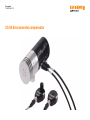
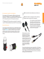
Renishaw XC-80 is an environmental compensator that accurately measures environmental conditions like air temperature, air pressure, and relative humidity. By doing so, it compensates the wavelength of the laser beam for variations in these factors, virtually eliminating any measurement errors. The XC-80 also accepts inputs from up to three material sensors, which measure the temperature of the machine or material under test.
Renishaw XC-80 is an environmental compensator that accurately measures environmental conditions like air temperature, air pressure, and relative humidity. By doing so, it compensates the wavelength of the laser beam for variations in these factors, virtually eliminating any measurement errors. The XC-80 also accepts inputs from up to three material sensors, which measure the temperature of the machine or material under test.


-
 1
1
-
 2
2
-
 3
3
-
 4
4
-
 5
5
-
 6
6
-
 7
7
-
 8
8
-
 9
9
-
 10
10
-
 11
11
-
 12
12
-
 13
13
-
 14
14
-
 15
15


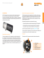
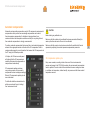
Renishaw XC-80 is an environmental compensator that accurately measures environmental conditions like air temperature, air pressure, and relative humidity. By doing so, it compensates the wavelength of the laser beam for variations in these factors, virtually eliminating any measurement errors. The XC-80 also accepts inputs from up to three material sensors, which measure the temperature of the machine or material under test.
Ask a question and I''ll find the answer in the document
Finding information in a document is now easier with AI
Related papers
-
Renishaw HC20 Installation guide
-
-
-
-
-
-
-
-
-