Page is loading ...

™
Solar
Power Kits
USER
MANUAL
Davis Instruments, 3465 Diablo Avenue, Hayward, CA 94545-2778 U.S.A. • 510-732-9229 • www.davisnet.com
R
Solar Power Kit, #6614 &
Heavy Duty Solar Power Kit, #6612
™

1
Welcome to
Solar Power Kit &
Heavy Duty Solar Power Kit
(6614 & 6612)
The Solar Power Kit and the Heavy Duty Solar Power Kit allow you to power and
shelter your Vantage Pro2 or Vantage Vue console, or your Weather Envoy or
Envoy8X for remote or field installations. The kits consist of three key elements: a
solar panel, a battery, and a regulator circuit; in a protective housing in which the
console or Envoy can be mounted.
The Solar Power Kit (product number 6614) comes with a 1.4 Ah battery. This
battery is sufficient, in most cases, to power wireless Vantage Pro2 consoles,
Vantage Vue consoles, and wireless Weather Envoys.
(The wireless outdoor sensor
suite is powered separately by the sensor suite’s solar panel.) It includes a 5 watt
solar panel.
The Heavy Duty Solar Power Kit (product number 6612) comes with a 12Ah
battery. It is required to power cabled consoles, cabled Weather Envoy, and
Envoy8X, or wherever extra power is needed. It includes a 5 watt solar panel.
In low light or poor conditions, you may need the Heavy Duty Solar Power Kit to
power wireless consoles or Envoys.
Note: Your Solar Power Kit comes with a battery designed to charge in temperatures as low as
-20°C. If your installation is in a location with low temperatures, you should replace the
battery with a Davis battery:
12 Amp. Hr. battery: product number 7011.025
1.4 Amp. Hr.battery: product number 7011.005
If your installation is in a warmer climate, you may replace the 12 Amp. Hr. battery with a
6-volt, 12 Ah, gel cell battery (standard motorcycle battery). You may replace the 1.4
Amp. Hr. battery with a 6-volt, 1.4 Ah, gel cell battery. These batteries will only charge at
temperatures above 0°C. (With either battery, your Solar Power Kit can function down to -
40°C.)

2
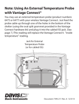
Contents of Package
Solar Panel and
Weather-Resistant Housing
Charging Circuit:
10’ console or Envoy
power cable (back)
Battery power cable
(middle)
Solar power cable
(front)
Charging Circuit:
10’ console or Envoy
power cable (back)
Battery power cable
(middle)
Solar power cable
(front)
To solar
panel
To solar
panel
6 volt, 1.40 amp.
hr. battery
Battery
platform
Battery
cable tie
6 volt, 12 amp.
hr. battery
Inside: Heavy Duty Solar Power Kit
Inside: Solar Power Shelter
Battery
platform
Battery
cable tie

3
The package contains the following:
• Weather-proof shelter with solar panel
• Hardware kit (as shown)
Tools for Setup
• Phillips head screwdriver
• Adjustable wrench or 7/16
'' wrench
• Drill and 3/16
'' (5 mm) drill bit (if mounting on a vertical surface)
¼" Lock Washers
¼" Hex Nuts
U-Bolts
Backing Plates
¼" x 1 ¼"
Lag Screws
Split Grommet
(with oval cable opening)
#6 ½” Pan Head
Philips Screws

4
Mounting Consoles in the
Solar Power Kit (1.4 Ah battery, #6614)
Note: You may mount the shelter before installing the console or Envoy. However, it may be
easier to do this at a workbench rather than in the field. In the case of an Envoy, you will
need a PC to set up the Envoy after you power it up.
The shelter has been designed to fit Davis consoles and Envoys. Inside the shelter,
outlines of the Vantage Pro2 console, Vantage Vue console, and Envoy will
indicate where they will be mounted in the shelter.
Inside the Solar Power Kit you may install:
• A wireless Vantage Pro2 console
• A Vantage Vue console
• A wireless Weather Envoy
Note: Use the Heavy Duty Solar Power Kit (#6612) to power a cabled Vantage Pro2, a cabled
Weather Envoy, or an Envoy8X.
Mounting a Wireless Vantage Pro2 Console in the Solar
Power Kit
1. Remove all packaging material.
2. Unplug the power cable from the jack closest to the back on the charging
circuit.
Console/Envoy Power
Battery power
Solar power

5
3. In order for the Vantage Pro2 console to fit in the shelter, you must move the
battery platform.
Remove the two screws and washers holding the battery platform in place.
4. Move it to the left side (as you face the shelter). Making sure the tray is flush
with the bottom, reinsert and tighten the screws.
5. Plug the console power cable back into the jack. (It fits only one way, with the
latch in back.)
6. The battery comes shipped with the positive cable unconnected to prevent
battery drain. Connect the positive (red) cable to the positive (red) terminal on
the battery.

6
7. On the back wall of the shelter, look for the embossed outline of a Vantage
Pro2 console and the screw holes marked “VP2.”
8. Insert the two ½'' #6 screws into the marked holes. The depth of the hole has
been specifically designed so that the screw will “bottom out” at the correct
depth. Do not overtighten.
Note: You may need to adjust the screw height for proper fit.
9. Point the console’s antenna down and push the kickstand back to its locked
position. Guide the two keyholes on the back of the console over the two
screws and pull the console downward to lock in place. (The solar power
cable will fit behind the console.)
10. Plug the console power cable into the console. Follow the console setup
procedures in your Vantage Pro2 Console Manual.
11. Close and lock the shelter.
E
E
VV VV
VP2 VP2
ENVOY Vantage VUE Vantage PRO2

7
Mounting a Vantage Vue console in the Solar Power Kit
1. Remove all packaging material.
2. Unplug the power cable from the jack closest to the back on the charging
circuit.
Console/Envoy Power
Battery power
Solar power

8
3. In order for the Vantage Vue console to fit in the shelter, you must move the
battery platform.
Remove the two screws and washers holding the battery platform in place.
4. Move it to the right side (as you face the shelter). Making sure the tray is
flush with the bottom, reinsert and tighten the screws.
5. Plug the console power cable back into the jack. (It fits only one way, with
the latch in back.)
6. The battery comes shipped with the positive cable unconnected to prevent
battery drain. Connect the positive (red) cable to the positive (red) terminal on
the battery.

9
7. On the back wall of the shelter, look for the embossed outline of a Vantage Vue
console and the screw holes marked “VV.”
8. Insert the two ½'' #6 screws into the marked holes. The depth of the hole has
been specifically designed so that the screw will “bottom out” at the correct
depth. Do not overtighten.
Note: You may need to adjust the screw height for proper fit.
9. Remove the kickstand from the console. Guide the two keyholes on the back of
the console over the two screws and pull the console downward to lock in
place.
10. Plug the console power cable into the console. Follow the console setup
procedures in your Vantage Vue Console Manual.
11. Close and lock the shelter.
E
E
VV VV
VP2 VP2
ENVOY Vantage VUE Vantage PRO2
N
S
WE
NE
SE
NW
SW
WIND
am
INSIDE OUTSIDE
RAIN RATE
CHILL
in/hr
F F
F
in
Vantage VUE
TEMPERATURE
HUMIDITY
BAROMETRIC
PRESSURE
RAINFALL
WEATHER
CENTER

10
Mounting a Wireless Weather Envoy in the Solar Power Kit
Note: You will need your PC to setup the Envoy after you power it up.
1. Remove all packaging material.
2. Unplug the power cable from the jack closest to the back on the charging
circuit.
Console/Envoy Power
Battery power
Solar power

11
3. In order for the Envoy to fit in the shelter, you must move the battery platform.
Remove the two screws and washers holding the battery platform in place.
4. Move it to the right side (as you face the shelter). Making sure the tray is flush
with the bottom, reinsert and tighten the screws.
5. Plug the power cable back into the jack. (It fits only one way, with the latch in
back.)
6. The battery comes shipped with the positive cable unconnected to prevent
battery drain. Connect the positive (red) cable to the positive (red) terminal on
the battery.

12
7. On the back wall of the shelter, look for the embossed outline of an Envoy and
the screw holes marked “E”
8. Insert the two ½'' #6 screws into the marked holes. The depth of the hole has
been specifically designed so that the screw will “bottom out” at the correct
depth. Do not overtighten.
Note: You may need to adjust the screw height for proper fit.
9. Point the Envoy’s antenna downward. Guide the two keyholes on the back of
the Envoy over the two screws and pull the console downward to lock in
place.
10. Plug the power cable into the Envoy. Use your PC to set up the Envoy as
shown in your Weather Envoy Manual.
11. Close and lock the shelter.
E
E
VV VV
VP2 VP2
ENVOY Vantage VUE Vantage PRO2
Vantage VUE
TEMPERATURE
HUMIDITY
BAROMETRIC
PRESSURE
RAINFALL
WEATHER
CENTER

13
Mounting an Envoy in the Heavy Duty Solar
Power Kit (12 Ah battery, #6612)
Inside the Heavy Duty Solar Power Kit shelter, you may install:
• An Envoy8X
• A cabled Weather Envoy
• A wireless Weather Envoy where low light or poor conditions require extra power.
Note: If using the Heavy Duty Solar Power Kit to power a cabled Vantage Pro2 console, or a
wireless Vantage Pro2 or Vantage Vue console that requires extra power, you will need to
install the console in a Universal Shelter (product number 6618) and connect it to the
Heavy Duty Solar Power Kit. See Using the Solar Power Kit or Heavy Duty Solar Power
Kit with a Universal Shelter (page 17).
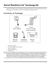
Mounting an Envoy8X (or Weather Envoy) in a Heavy Duty
Solar Power Kit
1. Remove all packaging material. (Don’t forget the cardboard behind the
battery.)
2. Unplug the power cable from the jack closest to the back on the charging
circuit.
Console/Envoy Power
Battery power
Solar power

14
3. In order for the Envoy to fit in the shelter, you must move the battery
platform.
Remove the two screws and washers holding the battery platform in place.
4. Move it to the right side (as you face the shelter). Making sure the tray is
flush with the bottom, reinsert and tighten the screws.

15
5. Plug the console power cable back into the jack. (It fits only one way, with the
latch in back.)
6. The battery comes shipped with the positive cable unconnected to prevent
battery drain. Connect the positive (red) cable to the positive (red) terminal on
the battery.
7. On the back wall of the shelter, look for the embossed outline of an Envoy and
the screw holes marked “E”
8. Insert the two ½'' #6 screws into the marked holes. The depth of the hole has
been specifically designed so that the screw will “bottom out” at the correct
depth. Do not overtighten.
Note: You may need to adjust the screw height for proper fit.
9. If you are mounting an Envoy8X or a wireless Weather Envoy, point the
Envoy’s antenna downward. If using a Weather Envoy, insert the data logger
into the Envoy. Guide the two keyholes on the back of the Envoy over the two
screws and pull the console downward to lock in place
E
E
VV VV
VP2 VP2
ENVOY Vantage VUE Vantage PRO2

16
10. Plug the main power cable into the Envoy.
11. If you are mounting a cabled Weather Envoy, remove the rubber plug from the
hole on the floor of the shelter, under the Envoy. Wrap the oval-hole split
grommet around the Envoy’s ISS cable and feed the cable up through the
hole, inserting grommet snuggly into the hole. Plug the ISS cable into the
Envoy.
12. Use your PC to set up the Envoy as shown in your Weather Envoy or Envoy8X
manual.
13. Close and lock the shelter.
Envoy8X

17
Using the Solar Power Kit or Heavy Duty Solar Power Kit
with a Universal Shelter
For some installations, you will need both a Solar Power Kit or Heavy Duty Solar
Power Kit and a Universal Shelter. For example, if you wish to power to a cabled
Vantage Pro2, you will need the Heavy Duty Solar Power Kit with the 12 Ah bat-
tery. However, there is not enough room in the shelter for both the large battery
and the console. You will need to mount your console in a Universal Shelter and
connect it to the Heavy Duty Solar Power Kit.
See your Universal Shelter User Manual for more information. It is also available
online at www.davisnet.com/support.
Using the Solar Power Kit or Heavy Duty Solar Power Kit
with an Extra Solar Panel Kit
For longer battery life in areas where there are extended periods of low or no light,
you may link your solar power kit’s shelter to an Extra Solar Panel Kit (product
number 6616). See your Extra Solar Panel Kit User Manual for more information.
It is also available online at www.davisnet.com/support.

18
Mounting the Shelter
Choose a location for your shelter. It can be mounted on a pole or a flat surface
such as a wall or a wooden post.
It is important that the shelter be mounted so that the solar panel gets the greatest
amount of sunshine: the solar panel should be facing south (in the northern
hemisphere) or north (in the southern hemisphere).
Mounting on a Pole
Mount the shelter onto a pipe with an outside diameter of 0.84'' to 1.84'' (21 mm
to 27 mm) using the U-bolts, backing plates, washers, and hex nuts provided.
Note: For mounting on larger diameter pipes, the housing can accommodate U-bolts with 5/6''
(8 mm) threads for pipes up to 2.40'' (61 mm) outside diameter (not provided).
1. While holding the shelter against the pole, place a U-bolt around the pole and
through the two holes at the top of the shelter.
2. Place a mounting plate over the bolt ends, then place a lock washer and a hex
nut on each of the bolt ends.
3. Tighten the nuts using an adjustable wrench or 7/16'' wrench.
4. Place the second U-bolt around the pole and through the two holes at the
bottom of the shelter. Put a backing plate, lock washer, and a hex nut on each
bolt end, and tighten the hex nuts.

19
Mounting on a Post or Flat Surface
Attach the shelter to the mounting surface in the desired location using the large
screws,1/4'' flat washers, and backing plates as shown below. Use a pencil or a
center-punch to mark the location of the pilot hole.
1. With a 3/16'' (5 mm) drill bit, drill two holes approximately 2'' (50 mm) apart.
Use a carpenter’s level to ensure the holes will be level.
2. Drill two more holes 7-1/32'' below the upper holes.
3. Insert the 1/4'' x 1-1/2'' lag screws through the backing plate and the holes at
the top of the shelter into the post.
4. Using an adjustable wrench or 7/16'' wrench, tighten the lag screws.
5. Repeat steps 3 and 4 for the bottom of shelter.
/