Page is loading ...

http://www.omega.com
e-mail: [email protected]
User’s Guide
PHB-215 pH Meter
PHB-220 pH/Conductivity Meter
PHB-225 pH/Ion Meter
PHB-250 pH/Ion/Conductivity Meter
PHB-215
pH m
eter

Servicing North America:
USA: One Omega Drive, Box 4047
ISO 9001 Certified Stamford, CT 06907-0047
Tel: (203) 359-1660 FAX: (203) 359-7700
e-mail: [email protected]
Canada: 976 Bergar
Laval (Quebec) H7L 5A1
Tel: (514) 856-6928 FAX: (514) 856-6886
e-mail: [email protected]
For immediate technical or application assistance:
USA and Canada: Sales Service: 1-800-826-6342 / 1-800-TC-OMEGA
SM
Customer Service: 1-800-622-2378 / 1-800-622-BEST
SM
Engineering Service: 1-800-872-9436 / 1-800-USA-WHEN
SM
TELEX: 996404 EASYLINK: 62968934 CABLE: OMEGA
Mexico and
Latin America:
Tel: (95) 800-TC-OMEGA
SM
FAX: (95) 203-359-7807
En Espan÷ol: (203) 359-7803 e-mail: [email protected]
Servicing Europe:
Benelux: Postbus 8034, 1180 LA Amstelveen, The Netherlands
Tel: (31) 20 6418405 FAX: (31) 20 6434643
Toll Free in Benelux: 06 0993344
e-mail: [email protected]
Czech Republic: ul. Rude armady 1868, 733 01 Kavrine-Hranice,
Czech Republic
Tel: 420 (69) 6311627 FAX: 420 (69) 6311114
e-mail: [email protected]
France: 9, rue Denis Papin, 78190 Trappes
Tel: (33) 130-621-400 FAX: (33) 130-699-120
Toll Free in France: 0800-4-06342
e-mail: [email protected]
Germany/Austria: Daimlerstrasse 26, D-75392 Deckenpfronn, Germany
Tel: 49 (07056) 3017 FAX: 49 (07056) 8540
Toll Free in Germany: 0130 11 21 66
e-mail: [email protected]
United Kingdom: 25 Swannington Road, P.O. Box 7, Omega Drive,
ISO 9002 Certified Broughton Astley, Leicestershire, Irlam, Manchester,
LE9 6TU, England M44 5EX, England
Tel: 44 (1455) 285520 Tel: 44 (161) 777-6611
FAX: 44 (1455) 283912 FAX: 44 (161) 777-6622
Toll Free in England: 0800-488-488
e-mail: [email protected]
omega.comomega.com
TM
OMEGA
®
OMEGAnet
SM
On-Line Service Internet e-mail
http://www.omega.com [email protected]
It is the policy of OMEGA to comply with all worldwide safety and EMC/EMI regulations that
apply. OMEGA is constantly pursuing certification of its products to the European New Approach
Directives. OMEGA will add the CE mark to every appropriate device upon certification.
The information contained in this document is believed to be correct but OMEGA Engineering, Inc. accepts
no liability for any errors it contains, and reserves the right to alter specifications without notice.
WARNING: These products are not designed for use in, and should not be used for, patient connected applications.

Quick Start Guide for pH Measurement . . . . . . . . . . . . . . . . . . . . . . . . . . . Page ii
Introduction
Menu Keys,Softkeys and Display . . . . . . . . . . . . . . . . . . . . . . . . . . . . . . . . . . . 1
Electrode Connectors and Inputs . . . . . . . . . . . . . . . . . . . . . . . . . . . . . . . . . . 2
LCD Display . . . . . . . . . . . . . . . . . . . . . . . . . . . . . . . . . . . . . . . . . . . . . . . . . . . 3
Function Keys . . . . . . . . . . . . . . . . . . . . . . . . . . . . . . . . . . . . . . . . . . . . . . . . . . 4
Electrodes
Preparing pH and Ion Selective Electrodes. . . . . . . . . . . . . . . . . . . . . . . . . . . 6
Connecting Electrodes. . . . . . . . . . . . . . . . . . . . . . . . . . . . . . . . . . . . . . . . . . . 6
Using and Storing Electrodes . . . . . . . . . . . . . . . . . . . . . . . . . . . . . . . . . . . . . . 7
pH Electrodes . . . . . . . . . . . . . . . . . . . . . . . . . . . . . . . . . . . . . . . . . . . . . . . . 7
Solid-State FET Electrodes. . . . . . . . . . . . . . . . . . . . . . . . . . . . . . . . . . . . . . . 7
Ion Selective Electrodes . . . . . . . . . . . . . . . . . . . . . . . . . . . . . . . . . . . . . . . . 7
Meter Setup
Meter Setup Menu . . . . . . . . . . . . . . . . . . . . . . . . . . . . . . . . . . . . . . . . . . . . . . 8
pH Mode
pH Mode Standardization Menu . . . . . . . . . . . . . . . . . . . . . . . . . . . . . . . . . . . 9
Cal Reminder Menu . . . . . . . . . . . . . . . . . . . . . . . . . . . . . . . . . . . . . . . . . . . . . 9
Select Custom Buffer Set. . . . . . . . . . . . . . . . . . . . . . . . . . . . . . . . . . . . . . . . . . 9
pH Mode Options Menu. . . . . . . . . . . . . . . . . . . . . . . . . . . . . . . . . . . . . . . . . 10
Standardizing and Measuring pH. . . . . . . . . . . . . . . . . . . . . . . . . . . . . . . . . . 12
Clearing Buffers . . . . . . . . . . . . . . . . . . . . . . . . . . . . . . . . . . . . . . . . . . . . . . . . 12
mV Mode
mV Mode Standardization Menu. . . . . . . . . . . . . . . . . . . . . . . . . . . . . . . . . . 13
mV Mode Options Menu . . . . . . . . . . . . . . . . . . . . . . . . . . . . . . . . . . . . . . . . 13
Clearing Relative mV Mode. . . . . . . . . . . . . . . . . . . . . . . . . . . . . . . . . . . . . . 13
Quick Start Guide for Ion Measurement. . . . . . . . . . . . . . . . . . . . . . . . . . . . . . . 14
Ion Mode
Ion Mode Standardization Menu. . . . . . . . . . . . . . . . . . . . . . . . . . . . . . . . . . 15
Standardizing and Measuring Ion . . . . . . . . . . . . . . . . . . . . . . . . . . . . . . . . . 16
Measuring Ion using a Known Addition type (incremental ion) method. . . 17
Quick Start Guide for Conductivity/Resistivity/Salinity/TDS Measurement. . . . 18
Conductivity/Resistivity/Salinity/TDS Modes
Conductivity/Resistivity/Salinity/TDS Standardize Menu . . . . . . . . . . . . . . . . 19
Conductivity/Resistivity/Salinity/TDS Options Menu. . . . . . . . . . . . . . . . . . . . 20
Data logging . . . . . . . . . . . . . . . . . . . . . . . . . . . . . . . . . . . . . . . . . . . . . . . . . . . . 21
Troubleshooting . . . . . . . . . . . . . . . . . . . . . . . . . . . . . . . . . . . . . . . . . . . . . . . . . . 22
Meter Specifications . . . . . . . . . . . . . . . . . . . . . . . . . . . . . . . . . . . . . . . . . . . . . . 23
pH Theory . . . . . . . . . . . . . . . . . . . . . . . . . . . . . . . . . . . . . . . . . . . . . . . . . . . . . . . 24
Ion Selective Electrode Theory . . . . . . . . . . . . . . . . . . . . . . . . . . . . . . . . . . . . . . 24
Determining Isopotential Point . . . . . . . . . . . . . . . . . . . . . . . . . . . . . . . . . . . . . . 25
RS-232 Serial Interface Meter Command Set. . . . . . . . . . . . . . . . . . . . . . . . . . . 26
Maintenance . . . . . . . . . . . . . . . . . . . . . . . . . . . . . . . . . . . . . . . . . . . . . . . . . . . . 28
Table of Contents
i

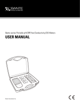
1.Connect power cable to meter connector on
the rear panel marked “power”and to AC power
source.
2.Connect the glass pH/ATC electrode to the
channel A BNC connector marked “ch.A”and to
the channel A temperature connector marked
“temp A”.
3.Verify the meter is in pH mode on channel A.Use
the Mode key and Channel key to set the meter
to the correct mode and channel if necessary.
(See Function keys).
4.Standardize the electrode by immersing the
electrode in a buffer,pressing Standardize, press-
ing 1) Auto-enter a buffer and following the
prompts.Repeat this step to enter each buffer.
The meter will check the electrode and buffers,
and give an error message if there is a problem.
Press Standardize to enter or clear buffers,select
buffers, set resolution,or set other parameters for
the current mode and channel.
5.The display shows the current measurement,and
indicates a stable reading with the indicator.
Press Cal Data to review and graph the elec-
trode calibration data.
ii
Quick Start Guide for pH Measurement
c
h
. A
re
f. A
c
h
T
e
m
p
. A
T
e
m
p
. B
R
S
2
3
2
C
p
o
w
e
r
c
o
n
d
. C
c
h
. A
re
f. A
c
h
T
e
m
p
. A
T
e
m
p
. B
R
S
2
3
2
C
p
o
w
e
r
c
o
n
d
. C
A 7.000
pH
25.0
°
C
No buffers.
Mode
Channel A: pH mode
Standardize Menu
1) Auto-enter a buffer
2) Manual buffer entry
3) Clear buffers
4) Options menu
5) Cal reminder menu
6) Select buffer set
channel
indicator
units
indicator
Channel
Standardize
A 7.000
pH
25.0
°
C
4.008 pH
7.000
entered
buffers
“power”
“ch. A”
“temp A”
s
s
stability
indicator
s

This Omega meter is a powerful,versatile and accurate instrument.It features
easy menu-based operation with easy to understand prompts and
electrode/standard error checking.
These meters feature many advanced options, such as programmable stability
criteria,programmable standardization reading delay times,multi-channel oper-
ation,fast reading update rates of twice per second for all channels,program-
mable alarms,programmable data logging of 500 data points and a superb RS-
232 serial interface for controlling the meter and obtaining data.
Omega meters use flash programmable ROM for the operating code.The meter
operating code can easily be upgraded as new features are made available.
Direct Menu Keys, Softkeys and Display
The meter uses six Direct Menu keys to access the menus and operations (such
as selecting pH mode,standardizing,checking electrode calibration data,
selecting the electrode channel).
There are four Softkeys that provide additional operations; these Softkeys
change their function as needed and each Softkey has an icon to indicate its
current function.
The display is a backlit quarter-VGA screen capable of displaying all four elec-
trode channels (of a PHB-250) simultaneously. The backlight will turn off after a 45
minute period of non-use; pressing any key will automatically turn the backlight
on again.
A S
7.001
pH
25.0¡C
4.008 pH
7.000
6/30/1998 02:28 PM
Denver Instrument
S
1
Introduction
Softkeys
Direct Menu
Keys
Direct Menu
Keys
Numeric
Keypad
PHB-215
pH m
eter

Electrode Connectors and Inputs
BNC ("ch.A" or "ch.B") connectors: pH,Ion
Selective Electrodes and ORP (redox) elec-
trodes attach to the meter through a BNC
("round twist-on") connector to channel A or
channel B (PHB-225 and PHB-250 only).
Temperature ("temp A" or "temp B") connec-
tors: use to connect the 2.5mm mini-phone
plug from the temperature sensor (built into
the pH electrode with the Omega standard
pH/ATC electrode) for Automatic Temperature
Compensation (ATC).
Reference ("ref.A" or "ref.B") connectors: use
for attaching a reference electrode tip-pin
plug when a separate reference electrode is
used.
Conductivity DIN (“ch.C conductivity”)
connector: use to connect a 4-band conduc-
tivity/ATC cell.These 4-band cells offer
improved linearity and stability over older 2-
band conductivity cells. (PHB-220 and PHB-250
only).
FET DIN ("ch.F FET") connector: use to connect
the Denver Solid-State Field Effect Transistor
(FET) pH/ATC electrode. These non-glass pH
electrodes offer certain advantages over con-
ventional glass pH electrodes.
Serial port ("RS232") DB-9 connector: use to
connect a serial printer or Personal Computer.
This bi-directional interface outputs data and
receives meter commands.
Power (“power”) connector: use to connect a
5.5mm OD x 2.1 ID coaxial connector with
12VDC at 500mA (center pin negative).
2
Introduction
ch. A
ref. A
temp
A
RS232C
power
ch. F
FET
ref
Connectors for PHB-250

D
Note: Not all of the following will display at the
same time.
A
. Result: current measurement.
B
. Units: displays the units for the current measure-
ment.Examples: pH,mV, mg/L F-,µS/cm or
W-cm.
C
. Softkey icons: show the current function
assigned to each softkey.
D
. Calibration due reminder: the icon means
a calibration is now due.
E
. Date and time: displayable in different formats.
F
. Datalogging: the icon indicates datalog-
ging is active.
G
. Buffers/Standards: in single channel mode,all
entered buffers or standards are displayed.A
“!”symbol beside a buffer indicates that buffer
is out of the entered calibration valid time (See
Calibration reminder,page 9).
H
. Temperature: displays the measured tempera-
ture when an electrode with ATC or separate
temperature probe is attached.Shows “M”
when a manually entered temperature is being
used.
I
. Alarm: “
*
”indicator means data is outside the
set alarm limits.
J
Channel: indicates which electrode channel
(input) is being displayed.Channel A and
Channel B (PHB-225 only) are BNC inputs.
Channel F is the FET electrode input.
K
. Stability: the indicates the electrode is sta-
ble to the selected criteria.
L
. Multiple Channel: display can show two
(PHB- 215),three (PHB-220 and PHB-225) or four
(PHB-250) electrode measurements with tem-
perature simultaneously.
M
. Out-of-range or non-valid reading: dashes indi-
cate a measurement is not available.This usual-
ly means the reading is out of range,or can
mean in ion mode that no standards have
been entered,or strict calibration has been set
and the calibration expired.
3
Display
*
A 7.000
pH
25.0
°
C
4.008 pH
7.000
9.999
6/30/1998 02:28 PM
A B
J
I
H
G
E
C
Single channel display
K
F
A 6.998
pH
24.6
°
C
B 1.02
mg/L
23.4
°
C F-
30-6-1998 14:28:05
Dual channel display
L
A pH
23.8
°
C
1998.6.30 14:28:30
M
s
s
s
CAL!
Log
S

A
. Mode: Selects the mode: pH,mV
(PHB-215),Ion (PHB-225 and PHB-250),
Conductivity - Resistivity-NaCl Salinity-
Practical Salinity-TDS (PHB-220 and
PHB-250) to use for the currently selected
channel (electrode input).
B
. Standardize: Enters buffers or standards
for the currently selected channel and
mode.Use to enter pH buffers, relative mV
offset,ion standards or conductivity /resis-
tivity standards.
Also used to change other settings which
affect the measurement.
C
. Cal Data: Displays and graphs buffers or
standards with time and date stamp and
electrode calibration data for the select-
ed channel and mode.
D
. Channel: Selects the channel(s) (elec-
trode inputs) to display.The PHB-215 can
display one or two channels simultane-
ously (Channels A and F).The PHB-225
can display one,two or three channels
simultaneously (Channels A, B and F).The
PHB-220 can display up to three channels
(Channels A,C and F).The PHB-250 can
display up to four channels (Channels A,
B,C and F).
E
. Setup: The Setup menu is used to set vari-
ous general meter settings,such as date
and time,display contrast,keypress beep
and serial port.
F
. Data Log: Displays the datalogging menu
used to set datalogging and view the
stored Data Log (see Datalogging).
G
. Clear: Exits from the current menu and
returns to the previous menu,cancels the
current operation or clears a number
entry.
H
. Enter/Print: Accepts numeric values,menu
selections or pending operations.In the
main measure screen,acts as a Print key,
sending all current measurements to a
printer/ computer through the serial port
and stores the measurements in the Data
Log.
I
. Softkeys: These four keys access different
operations at different times.Most menus
offer a “Help”softkey and the “Measure”
softkey, which allows a direct return to the
main measuring screen,exiting all menus
immediately. The “Up Arrow”and “Down
Arrow” softkeys offer one way to select a
menu item.The “Left Arrow”key is a back-
space,active during number entry.
J
. Numeric Keys: Pressing a number key
selects a numbered item in a menu.The
number keys also allow entering values for
buffers, standards,and various meter set-
tings.
4
Function Keys
E
–
+
Help
Measure
Scroll up
Scroll down
Backspace
Graph
Exponent number entry
Incremental ion method
Measure lock
Measure unlock
Softkeys

5
Function Keys
Mode
Standardize
Cal Data
Channel
Enter/Print
Clear
Setup
Data Log
?
A
B
C
D
E
F
G
H
I
J
Channels
The Channel key is used to turn on or off each
available channel.In single-channel operation,
additional information for the selected channel is
provided,including a display list of all entered
buffers or standards.In multi-channel operation,
the Mode,Standardize and Cal Data menus ask
for the channel before accessing the menu.
The PHB-215 offers single or dual channel opera-
tion using channel A ( pH and ORP electrodes)
and channel F (Solid-state FET pH electrode).The
PHB-225 offers up to three-channel simultaneous
operation of channel A and channel B (pH,ORP
and Ion Selective Electrodes) and channel F
(Solid-state FET pH electrode).
The PHB-220 has Channel A (pH and ORP elec-
trodes),Channel C (Conductivity cells) and
Channel F (solid-state FET pH electrode).The
PHB-250 provides up to four channel measure-
ment with Channel A and Channel B (pH and
ORP and Ion Selective electrodes),Channel C
(Conductivity cells) and Channel F (solid-state
FET pH electrode).
Configure Display
1) Turn channel A on/off: ON
2) Turn channel B on/off: ON
3) Turn channel F on/off: OFF
4) Turn channel C on/off: ON
5) Measurement screen
PHB-250 Select Channel
screen
Channel

The meter allows you to use a variety of glass mem-
brane (“glass”) pH/ATC electrodes,ion selective elec-
trodes,Conductivity/ATC cells,the Omega Field Effect
Transistor (FET) Solid-State pH/ATC electrode,tempera-
ture (ATC) probes,combination electrodes using a BNC
connector, or separate electrode pairs with BNC con-
nector and reference pin.
Preparing Electrodes and Conductivity Cells
Remove the wetting cap or storage cap from the elec-
trode.Before first using your pH electrode or whenever
the electrode is dry,soak it several hours in an elec-
trode filling or storage solution (3 Molar KCl solution) or
in a buffer for pH electrodes.Condition ISE’s in the rec-
ommended solutions. Rinse Conductivity cells with
deionized water before use.
Connecting Electrodes
pH, ORP or ISE electrodes (with BNC connector):
Connect the electrode to the BNC input,either chan-
nel A or channel B (PHB-225 and PHB-250 only),located
at the rear of the meter.Push in and rotate the elec-
trode’s BNC connector until it locks in place.Connect
the ATC connector to the temp.A or temp.B connec-
tor. To disconnect,twist the BNC connector in the
opposite direction and pull.
Electrode Pair Using a Reference Electrode (with
Reference Pin Plug):
Connect the indicating electrode to the BNC input.
Connect the reference electrode to the Reference
input.Push the electrode’s tip pin plug into the input to
connect and pull out to disconnect.
Conductivity Cells (with DIN connector):
Align and push in the DIN connector fully to the chan-
nel C input (PHB-220 and PHB-250 only).Pull carefully to
disconnect.
6
Electrodes
To measure Use channel (connector)
pH A (BNC)*
or
B (BNC)*
mV (ORP) A (BNC)*
or
B (BNC)*
ion (ISE) A (BNC)*
or
B (BNC)*
Conductivity C (DIN)
Resistivity C (DIN)
Salinity C (DIN)
TDS C (DIN)
pH (FET) F (mini-DIN)
*Separate reference electrodes can be used with “Ref A” or
“Ref B”connectors
ch. A
ref. A
temp
A
ref
ch. F
FET
BNC
Connector
Channel C
Conductivity Input
ATC
Connector
Channel F
FET pH Input

Using and Storing Electrodes
pH Electrodes
• Provide moderate stirring for faster electrode
response.
• Leave the fill hole open during all use.
• Rinse the electrode between each measurement
with a portion of the next sample or buffer to be
measured,or with deionized or distilled water.
• Keep glass electrodes wet when not being used
by placing some electrode filling solution in the
wetting cap and storing with the wetting cap on.
• Keeping glass electrodes “wet”will improve their
performance.Store electrodes in electrode filling
solution or storage solution (3M KCl).
Solid-State FET Electrode
• All models allow use of both standard glass
pH/ATC and Solid-State FET (Field Effect Transistor)
pH/ATC electrodes.The meter can store a cali-
bration for both types of electrodes.Plug the FET
electrode into the channel F mini-DIN input.
• Allow the FET about 1 minute to stabilize when
first connected.The FET electrode can be stored
dry or in electrode storage solution. Provide mod-
erate stirring.
Ion Selective Electrodes
• Add proper amount of Ionic Strength Adjuster
(ISA) to all standards and samples,usually 1 mL
ISA to 50 mL standard or sample.
• Provide moderate stirring for faster electrode
response.
• Rinse the electrode(s) between each measure-
ment with a portion of the next sample or stan-
dard to be measured,or with deionized or dis-
tilled water.
• Follow the instruction sheets for the individual
electrode.Store as recommended.
Conductivity Cells
• When changing samples or standards,immerse
the cell into the new solution,then lift and allow
solution to drain out.Repeat two more times.
• Gently tap cell to dislodge air bubbles.
7
Electrodes
Store with wetting
cap and Fill
Solution (3M KCl)
Provide
moderate
stirring
Store FET and
Conductivity
Cells dry

Meter Setup Menu
Press Setup to access the Meter Setup menu:
1.Time and date menu: use to set the time format
(HH:MM AM/PM or HH:MM:SS),set the time, set the
date format (MM/DD/YY,DD-MM-YY or YYYY.MM.DD),
and set the date.
2.Select temperature units: use to select temperature
measurement and display in degrees Celsius,degrees
Fahrenheit or Kelvin.
3.Select contrast: use to select the display contrast,mak-
ing the displayed characters lighter or darker.Select
setting “5”for typical conditions.
4.Select baud rate: use to set the serial RS232 port baud
rate. This must match the baud rate setting of the
printer or computer being used with the meter.
5.Setup serial port: use to configure the serial port start
bits and parity setting. This must match the settings of
the printer or computer being used with the meter.
6.Keypress beep on/off: use to turn on or off a "beep"
upon each keypress as an audible signal that a key
has been pressed.
7.Select video color scheme: use to set the display to
black characters on a white background or white
characters on a black background.
8.Show meter information: use to show the meter
model,software version and serial number.
9.Enable measure lock: use to enable the measure lock
where a stable measurement is locked (frozen) for
later review. Stability criteria should be set to SLOW for
all channels and modes in use.
0.Enable strict calibration: use to set strict calibration
where no measurements are displayed if the calibra-
tion reminder has expired.
“±”Set screen saver timeout: use to set a time for the
backlight to turn off and the screensaver to activate.
"•" Restore factory defaults: use to reset all settings to
factory defaults.On occasion it may be useful to
completely reset the meter,for example,if other users
have changed a setting.
Warning!
A reset also clears all electrode standardizations.
8
Meter Setup
!
Meter Setup Menu
1) Time and date menu
2) Select temperature units
3) Select contrast
4) Select baud rate
5) Setup serial port
6) Keypress beep on/off
7) Select video color scheme
8) Show meter information
9) Enable measure lock
0) Enable strict calibration
±) Set screen saver timeout
•) Restore factory defaults
Setup
Select Time Format
1) hr : min : sec
2) hr : min AM/PM
Select Date Format
1) mm / dd / yyyy
2) dd – mm – yyyy
3) yyyy.mm.dd
Enable Measure Lock
Display lock/unlock softkey?
1) Yes
2) No
If “measure lock” is enabled, a
“lock” soft key will appear on
the measurement screen
Enable Strict Calibration
Require calibration?
1) Yes
2) No
If strict calibration is enabled,
no measurements will be
displayed for a channel with an
expired cal reminder.

9
pH Mode
pH Mode Standardize Menu
Press Mode and select 1) pH.
Press Standardize and the pH Mode Standardize
Menu appears:
1.Auto-enter a buffer: use to add a new buffer which
is auto recognized by the meter,or update an exist-
ing buffer.Follow the prompts.
2.Manual buffer entry: use to enter a buffer value by
manually entering the pH of the buffer.
3.Clear buffers: use to clear all buffers entered for the
current channel (pH mode).If all entered buffers are
being re-entered,it is usually not necessary to clear
buffers before re-entering them.
4.Options Menu: A menu of additional specific pH
mode settings. (See page 10).
5.Cal reminder menu: use to set a timer reminding
you to recalibrate.A icon will appear on the
main screen and an exclamation mark will appear
beside the buffers for which time has expired.
The calibration reminder is a reminder of when
electrode calibration (with buffers) should be
redone.It is based on elapsed time from the oldest
entered buffer.
If strict calibration is set (see Meter Setup Menu),when
a calibration has expired the icon appears,and
"- - - " is displayed in place of the measurement. No
measurements can be obtained until a calibration is
performed.
Note: When strict calibration is set,the calibration
reminders for all channels are turned ON, and can't
be turned off from the Cal Reminder Menu.
6.Select buffer set: There are five auto-recognition
buffer sets and the option to configure and use a
custom buffer set of your own.
Select custom buffer set
Use Custom Buffer Set to make a set of buffers con-
taining the specific buffers in use (up to five buffers).
Select Custom Buffer Set,configure the custom
buffer set,then buffers from this set will be automati-
cally recognized and entered.
Custom buffers can have any numeric pH value,or
can be selected from the built-in temperature cor-
rected buffers. Using the built-in buffers allow tem-
perature correction of the pH values of the buffers,
offering more accuracy.
Channel A: pH mode
Standardize Menu
1) Auto-enter a buffer
2) Manual buffer entry
3) Clear Buffers
4) Options Menu
5) Cal reminder menu
6) Select buffer set
Standardize
Channel A: pH mode
Manual Buffer Entry
Enter the actual pH of this
buffer, after correcting
for temperature:
pH
Press Enter to accept.
Channel A: pH mode
Cal Reminder Menu
1) Turn reminder On/Off: OFF
2) Set reminder interval:
01, 00 : 00 days, hr : min
3) Standardization menu
When the cal reminder expires, a “CAL!”
(or “!”) icon will be displayed with the
measurement and with each expired stan-
dard. If strict cal is ON, reminders are
always ON, and expired channels show no
measurements.
Channel A: pH mode
Select Buffer Set
1) 2, 4, 7, 10, 12 at 25C
2) 2, 4, 7, 10, 12 at 20C
3) 1, 3, 6, 8, 10, 13
4) 1.68, 4.01, 6.86, 9.18, 12.46
5) 1.09, 3.06, 4.65, 9.23, 12.75
6) Select custom buffer set
Custom Buffer
No buffers
CAL!
Channel A: pH mode
Configure Custom Buffer Set
1) Add a “built-in” buffer
2) Add a manual buffer
3) Delete a buffer
4) Standardize menu
Custom Buffer Set
No buffers
CAL!

pH Mode Options Menu
1.Select resolution: use to set pH readings to 0.1,0.01,
or 0.001 pH units.
2.Select stability criteria: use to set stability criteria to
slow,medium or fast to match the electrode's speed
of response and the variability of the signal allowed
for a “stable”( ) measurement.
3.Select signal averaging: use to set filtering of the
electrode signal to very slow (10 readings),slow (8),
medium (6),fast (4) or very fast (2). Slower settings
give more stable readings,although may require
longer times to reach stability.
4.Set standardization delay: use to set a reading delay
time for the meter to wait before accepting an elec-
trode signal during standardization.Programming a
standardization reading delay helps slow responding
electrodes reach equilibrium before the electrode
signal is accepted.
5.Set pH slope: use to set a known electrode slope
used by the meter with a zero- or single-point stan-
dardization.The normal default slope is 59.16 mV/pH.
The meter allows between 80 and 120 % efficiency to
be entered.
6.Standardize menu: Returns to the pH mode
Standardization Menu.
7.Manual temperature menu: use to set a temperature
to be used in the absence of an ATC probe or when
manually overriding the ATC.
8.Data alarm menu: use to set pH limits.If the limits are
exceeded an alarm indication (“
*
”) is displayed and
recorded with any data points placed in the Data
Log.
9.Set isopotential point: use to set an isopotential point
for use in high accuracy electrode measurements
(See Isopotential,page 20).
10
pH Mode
Channel A: pH mode
Options Menu
1) Select resolution
2) Select stability criteria
3) Select signal averaging
4) Set standardization delay
5) Set pH slope
6) Standardize menu
7) Manual temperature menu
8) Data alarm menu
9) Set isopotential point
S

Notes:
1.Auto-recognized buffers are found in the Auto-rec-
ognized built-in buffer sets.These buffers are auto-
recognized by the meter, and are also automatically
temperature corrected for the variation of buffer pH
with temperature.
2.When manually entering buffers,the exact pH of the
buffer at the current temperature must be entered.
All buffers change pH with temperature.For best
accuracy,either use the built-in buffers or make sure
manually entered buffers are at the expected tem-
perature (so that their pH as entered is correct).
3.Auto-recognition Buffer Sets:
1) 2,4,7,10, 12 (nominal value adjusted at 25°C)
2) 2,4,7,10, 12 (nominal value adjusted at 20°C)
3) 1,3,6,8, 10,13
4) 1.68,4.01,6.86,9.18, 12.46 (NIST buffers)
5) 1.09,3.06,4.65,9.23, 12.75 (DIN buffers)
6) Select custom buffer set
4.Temperature Correction of Electrodes and Buffers
The meter automatically compensates for the temper-
ature dependence of the electrode's response when
measuring pH.The meter also compensates for buffer
change in pH value with temperature.Temperature
compensation is based on temperature either from an
ATC probe or a manually entered temperature.
Using a Solid-state FET (Field Effect Transistor)
pH/ATC Electrode
By turning channel F (FET) on,an Omega FET pH/ATC
electrode can be directly used.pH and mV modes are
available with the FET electrode.FET devices can have
large offset potentials that vary with each transistor
chip,so Manual buffer entry must be used to enter the
first buffer.After one buffer has been entered using
“Manual buffer entry”, following buffers can usually be
entered with “Auto-enter a buffer”.
pH Mode
Actual Buffer pH vs. Temperature
pH 4.00(4.01)/7.00/10.00 buffer (nominal 25°C)
Temperature Buffer 4 Buffer 7 Buffer 10
(°C)
30 4.016 6.991 9.947
25 4.008 7.003 10.000
20 4.003 7.020 10.057
15 4.000 7.042 10.119
10 3.998 7.069 10.187
11

12
Standardizing and Measuring pH
1.Immerse the electrode in a buffer and stir moderate-
ly.The meter displays the current pH measurement.
2.Allow the electrode sufficient time to reach
equilibrium.
3.Press Standardize,then press either 1) Auto-enter a
buffer or 2) Manual buffer entry.
4.Follow the prompts on the display.
5.The meter waits for a stable signal,automatically rec-
ognizes the buffer (if using “Auto-enter”),checks the
electrode and buffer and enters the buffer.The
entered buffer appears in the display.
6.Alternatively,if the signal is not stable,you can press
Enter when the reading stabilizes according to your
tolerance criteria.The meter then enters the buffer.
7.Repeat steps 1 through 4 to enter a second,third,
fourth or fifth buffer.With more than one buffer the
meter performs a diagnostic check on the electrode.
The electrode is considered good if the slope is
between 90 to 105%.If a sixth buffer is entered,the
buffer farthest away is replaced by the new buffer.
Hints to achieve better accuracy:
• During standardization,allow time for the electrode
to stabilize before entering the buffer into the meter.
• Standardize using at least two buffers,bracketing the
expected pH of your samples.
• Standardize at least daily for the most accurate read-
ings.
• Open the Fill Hole on the electrode.
• Stir all buffers and samples.
• Rinse the electrode with DI water between samples
and buffers.
• Always use fresh buffers.
Clearing Buffers
Press Standardize,then press 3) Clear buffers to clear
buffers. If all previously entered buffers will be re-
entered,it is not necessary to clear buffers since the
meter will replace the previous values.If re-entering
only some buffers, all the old buffers should be cleared.
Channel A: pH mode
pH Checklist
Prepare buffer or sample.
Rinse electrode.
Place electrode in solution.
Stir moderately.
Press Enter to continue.
Channel A: pH mode
Standardize Menu
1) Auto-enter a buffer
2) Manual buffer entry
3) Clear buffers
4) Options menu
5) Cal reminder menu
6) Select buffer set
Standardize
Channel A: pH mode
Manual Buffer Entry
Enter the actual pH of this
buffer, after correcting
for temperature:
pH
Press Enter to accept.
mV
4 7 10
pH buffers
samples

Electrode Potential,mV
Titrant Volume,mL
Redox Titration
Standardize
Millivolt measurements are used to measure ORP (oxi-
dation-reduction potential) or redox potential,to
check performance of pH or Ion Selective Electrodes,
and for redox titrations.
The meter will measure millivolts (mV) by pressing Mode
and selecting 2) mV.Relative mV can be measured
by entering a mV offset or using the current mV value
as the mV offset.
mV Standardization Menu
In mV mode,press Standardize and the mV mode
Standardization Menu appears:
1.Auto-enter mV offset: use to set the relative mV off-
set equal to the current mV reading. The current mV
becomes 0.0 relative mV.
2.Set mV offset: use to manually enter a mV offset.
3.Clear mV offset: use to clear any offset that has
been entered,returning the meter to absolute mV
mode.
4.Options menu: a menu of additional settings specif-
ic to the mV mode.See below.
mV Mode Options Menu
1.Select resolution: use to set mV readings to 1 or 0.1
millivolt resolution.
2.Select stability criteria: use to select stability criteria
for slow,medium or fast response which use a tight,
average or loose requirement to indicate a “stable”
( ) reading.
3.Select signal averaging: use to set the meter to
average readings that are very slow (10 readings),
slow (8),medium (6), fast (4) or very fast (2).
4.Set standardization delay: use to set a length of time
for the meter to wait before entering a relative mV
standardization.
5.Set mV offset: use to manually enter a mV offset
(same as in the mV Standardize menu).
6.Standardization menu: returns to the mV
Standardization Menu.
Clearing Relative mV Mode
Press Standardize,then press 3) Clear mV offset to clear
offset and return the meter to absolute mV mode.
mV Mode
Channel A: mV mode
Standardize Menu
1) Auto-enter mV offset
2) Set mV offset
3) Clear mV offset
4) Options menu
Channel A: mV mode
Options Menu
1) Select resolution
2) Select stability criteria
3) Select signal averaging
4) Set standardization delay
5) Set mV offset
6) Standardize
13
S

14
Quick Start Guide for Ion Measurements
1.Connect the Ion Selective Electrode (ISE) and
Reference Electrode,if required,to the
meter.”Combination”ISE’s have a reference
electrode built-in,and do not require a sepa-
rate reference electrode or connection.
2.Prepare two or more ion standards at concen-
trations bracketing typical sample solutions.
Add the appropriate Ionic Strength Adjuster
solution to each standard.
3.Set the meter to display the correct channel
(the channel with the ISE attached,either A or
B) using Channel.Set the meter to Ion mode:
press Mode,then 3) Ion.
Note: The meter will display “— — —” (no valid
data) until an ion standard has been entered.
4.Place the electrode(s) in the standard,provide
stirring (a magnetic stirrer is recommended),
and allow sufficient time (1 to 5 minutes
depending on the ISE) for the electrode to
reach a stable signal.
5.Press Standardize,1) Enter a standard and fol-
low the prompts.Repeat these steps to enter
up to seven ion standards.See the
Standardizing and Measuring Ion section for
more information.
6.Check the ISE response by pressing Cal Data to
see the standards and the ISE slope between
calibration points (standards).The meter will
allow an ion electrode slope between 5.92
mV/decade (10% slope) and 70.99
mV/decade (120% slope).
c
h
. A
re
f. A
c
h
T
e
m
p
. A
T
e
m
p
. B
R
S
2
3
2
C
p
o
w
e
r
Mode
Channel
+
ISA
Example: 1 mg/L 10 mg/L Ionic Strength
Adjuster
BNC
ref
measuring or
Combination ISE
reference
Cal Data
Channel A:
Select Mode
1) pH
2) mV
3) Ion
Channel A: ion mode
Ion Cal Data
1.00 mg/l 08/01/1998 08:32 AM
57.15 mV/decade
10.0 mg/l 08/01/1998 08:35 AM
E
Channel A: ion mode
Standardize Menu
1) Enter a standard
2) Set ion slope
3) Clear standards
4) Options menu
5) Cal reminder menu

Ion Mode Standardization Menu
Select channel A or B.Press Mode and then press 3) Ion for ion
mode.Press Standardize and the Ion Mode Standardize Menu
appears.
1.Enter a standard: use to add a new standard or update (re-
enter) an existing standard.Follow the prompts.With the first
standard you select the ion name and units.
2.Set ion slope: use to manually enter a slope for the selected
ion electrode.Used with a one-point ion calibration.Useful if
the ISE has a known,stable slope,so that measurements can
be made after entering a single ion standard.
Note: when two or more standards are entered,the meter
uses the actual determined slope(s).
3.Clear standards: use to clear standards for the electrode
standardization selected.
4.Cal reminder menu: use to set a timer reminding you to
recalibrate.A icon will appear on the main screen
and an exclamation mark will appear beside the standards
which need to be re-entered.
5.Options Menu: use to set various additional parameters to
the ion mode.See below.
Ion Mode Options Menu
1.Resolution: use to set the readings to 1,2,or 3 significant dig-
its.
2. Select stability criteria: use to set the stability criteria to slow,
medium or fast to match the electrode's speed and stability
of response,providing tight,medium and loose requirements
for a stable ( ) indication.
3.Select signal averaging: use to set filtering of the electrode
signal to very slow (10 readings),slow (8),medium (6),fast (4)
or very fast (2). Slower settings give more stable readings,
although may require longer times to reach stability.
4.Set standardization delay: use to set a reading delay time for
the meter to wait before accepting an electrode signal dur-
ing standardization.Programming a standardization reading
delay helps slow responding electrodes reach equilibrium
before the electrode signal is accepted.Delays of one
minute for fast ISE’s and five to ten minutes for slow ISE’s are
appropriate.
5.Set ion slope: use to enter a known ion electrode slope for a
one point standardization.
6.Standardize menu: returns to the ion standardize menu.
7.Manual temperature menu: use to set a manual temperature
for use in the absence of an ATC probe or when manually
overriding the ATC.
8.Data alarm menu: use to enter ion limits to be entered.If the
limits are exceeded an alarm indication (“
*
”) is displayed.
9.Set isopotential point: use to enter an isopotential point. See
page 20.
0.Enable incremental: use to turn on the known addition/sub-
traction type ion methods.See page 17.
Ion Mode
Channel A: ion mode
Standardize Menu
1) Enter a standard
2) Set ion slope
3) Clear standards
4) Options menu
5) Cal reminder menu
Channel A: ion mode
Options Menu
1) Select resolution
2) Select stability criteria
3) Select signal averaging
4) Set standardization delay
5) Set ion slope
6) Standardize menu
7) Manual temperature menu
8) Data alarm menu
9) Set isopotential point
0) Enable incremental modes
15
CAL!
S

16
Standardizing and Measuring Ion
Standardizing and Measuring Ion
1.Set the meter to ion mode (use Mode) and turn
ON the channel (use Channel) with the Ion
Selective Electrode (either Channel A or B).
The meter displays “— — —”, indicating no valid
measurement,until at least one ion standard has
been entered.
2.Prepare a standard,and add the appropriate
Ionic Strength Adjuster (ISA) solution to the stan-
dard.
3.Immerse the electrode(s) in the solution and stir
continuously.
4.Press Standardize,select the correct channel if
prompted to do so,and select 1) Enter a stan-
dard to add a standard.If this is the first standard
to be entered,select the ion name and units.
Follow the prompts.Be sure to allow enough time
for the electrode to reach a stable signal.
Note: The default standardization delay for ion
mode is 30 seconds.This can be set by the user.
See Ion Mode Options Menu,page 15.
5.The meter waits for a stable signal and enters the
standard.The entered standard appears in the
display (in single channel mode).Alternatively,if
the signal is not stable,you can press Enter when
the reading stabilizes according to your toler-
ance criteria.The meter then enters the stan-
dard.
6.Repeat steps 2 through 5 to enter additional
standards.Up to seven standards can be
entered.With more than one standard,the meter
performs a diagnostic check on the electrode.
Helpful Hints:
• Provide stirring.
• Allow the electrode time to reach a stable read-
ing before entering the standard into the meter.
• To achieve better accuracy, standardize using at
least two standards, bracketing the expected
range of your samples.
• Standardize from low to high concentrations.
• Always use fresh standards.
• Use standards and samples near the same tem-
perature.
• Remember to add Ionic Strength Adjuster to
each standard and sample.
mV
ion standards
log [ion]
Channel B: ion mode
A 25.0°C
No standards.
08/01/1998 08:40 PM
Channel B: ion mode
Ion Checklist
Prepare standard or sample.
Add Ionic strength Adjuster.
Rinse electrode.
Place electrode in solution.
Stir moderately.
Press Enter to continue.
Standardize
Channel A: ion mode
Standardize Menu
1) Enter a standard
2) Set ion slope
3) Clear standards
4) Options menu
5) Cal reminder menu
/