Page is loading ...

Optional Output Connectors for CE Series Amplifiers
Installation Guide (CEAS1/CEAS2)
page 1 of 2
128271-1
10/99
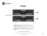
CE Series Amplifier 5-Way Binding Post
Output Connectors
PART # CEAS1
PART # CEAS2
P.O. Box 1000 Elkhart, IN 46515 Phone: (219) 294-8000 Fax: (219) 294-8250
Web Page: http://www.crownaudio.com
CE Series Amplifier Barrier Strip
Output Connectors
OUTPUT CONNECTOR
TOOLS REQUIRED:
Torx #T-15 screwdriver
INCLUDES:
2 - #8 x 1¼ in. screws
• CE optional output connector
WARNING: CEAS1 AND CEAS2 OPTIONAL OUTPUT
CONNECTORS MUST BE INSTALLED BY A QUALIFIED
SERVICE CENTER.
Follow the installation instructions provided on the next
page to install your CE Optional Output Connector. Once
installed, your CE amplifier will offer barrier block or 5-way
binding post output connectors (depending on the kit
ordered).
Note that installing the optional output connectors does
NOT defeat the Neutrik
®
Speakon connectors on the back
panel of the amplifier. If, at any time, you prefer to use the
standard Neutrik
®
Speakon
®
output connectors, it is not
necessary to remove the optional output connector panel
from the amplifier. Instead, simply connect your speaker
wires to the Speakon
®
output connectors instead of the
optional output connectors.
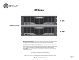
CE Series Amplifier with Optional Output Connector Installed

Optional Output Connectors for CE Series Amplifiers
Installation Guide (CEAS1/CEAS2).
page 2 of 2
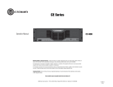
CE Series Optional Output Connector Wire Locations
Red wire to relay K100 “ON” terminal (location A).
Orange wire to relay K200 “ON” terminal (location B).
Black wire to WP7 lug (location C).
P.O. Box 1000 Elkhart, IN 46515 Phone: (219) 294-8000 Fax: (219) 294-8250
Web Page: http://www.crownaudio.com
INSTRUCTIONS:
1. Turn down level controls.
2. Turn off amp.
3. Unplug power cord.
4. Remove the four T-15 torx-head screws from the top cover, and retain screws.
Remove top cover.
5. Remove the two T-15 torx-head screws from the rectangular cover plate on the
back panel, and retain screws. Remove cover plate and discard.
6. Install CEAS1/CEAS2 in back panel opening and affix with cover-plate screws.
7. Attach wires to main PWA as follows (refer to the illustration above):
8. Reinstall top cover.
9. Connect wires to new output panel.
10. Plug in power cord.
11. Turn on amp.
12. Turn up the level controls to desired volume.
/