Page is loading ...

GEH-2885H
INSTRUCTIONS
Lowmount
®
Luminaire
Installation and Maintenance
READ THOROUGHLY BEFORE INSTALLING
GENERAL
This luminaire is designed for indoor applications and consists of
two assemblies, ballast and optical, which are shipped in separate
packages. The packing slip lists the ballast and optical assembly
catalog numbers in addition to the complete luminaire catalog
number. Check to see that you received the correct material.
If the luminaire you ordered has a polycarbonate refractor, please
pay particular attention to the following statement.
All polycarbonates and articles made from polycarbonates will
yellow with time. The rate of yellowing is determined by the specific
material, any additives and coatings, as well as the optical temperature
and exposure to ultraviolet (UV) light.
This yellowing can reduce the light output and impact resistance of
products made from polycarbonate resin. In no case should the
maximum voltage recommendations listed for the luminaire be
exceeded. Contact factory for more information.
UNPACKING
The luminaire is supplied with a lightweight hanger hub and
locking nut which are threaded together, and included in the same
carton with the ballast.
INSTALLATION
CAUTION
Unit will fall if not installed properly
• Follow installation instructions
WARNING
Risk of electric shock
• Turn power off before servicing
– see instructions
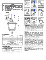
Rotate 30°
Figure EFigure D
Twist the supply leads loosely together and slip the ballast assembly
up over the hanger hub and at an angle of about 30° counter-clockwise
from the final desired position (see Figure D). Then rotate the ballast
assembly clockwise about 30° until it drops securely into the seated
position. Check for proper seated position by trying to rotate the
assembly counter-clockwise while it is supported by the hanger hub.
After assuring that the ballast assembly is properly seated, screw the
knurled locking nut back down on the hanger hub finger-tight,
(except wet location units) (see Figure E). Once the knurled nut is in
position it should not be possible to disconnect or rotate the ballast
assembly without loosening the nut again.
CONDUIT MOUNTING
Fasten the hanger hub to 3/4-inch conduit by threading the
assembly of locking nut and hanger hub onto the conduit. Wrench
flats are provided on the hanger hub so that it can be tightened
securely to the conduit (minimum of five full turns). Orient any arrow
on the bottom of the hanger hub in the direction you wish the wiring
box to face. Then tighten down the set screw to lock the hanger hub to
the conduit (see Figure B). Next, loosen the knurled locking nut until it
disengages and is free to move up the conduit (see Figure C).
NOTE: When installing units provided with a gasket between
the hanger-hub and knurled locking nut, it is necessary to
securely hand-tighten the locking nut, to insure that the gasket
is compressed fully around the pipe nipple to prevent entrance
of moisture.
PENDANT MOUNTING
Pendant mounting provisions are available as a factory-installed
accessory or as a customer-installed accessory. The factory-installed
hook or loop and cord are supplied ready to hang and plug in. If the
pendant mounting accessories are shipped separately, the nipple
Figure C
Figure B
WARNING
Risk of fire
• Keep combustible materials away
from lens – see instructions
• Use lamps specified on nameplate
These instructions do not purport to cover all details or variations in equipment nor to provide for every possible contingency to be met in connection with installation, operation or
maintenance. Should further information be desired or should particular problems arise which are not covered sufficiently for the purchaser’s purposes, the matter should be referred
to GE Lighting Solutions.
g
GE
Lighting Solutions

WIRING
Make all electrical connections in accordance with the National
Electrical Code and any applicable local code requirements.
(see Figure G).
Verify that supply voltage is correct by comparing it to
nameplate.
Connect the green fixture ground lead to a suitable grounded
conductor. Replace wiring compartment-cover when wiring is complete.
Do not remove insulated connectors from wires not needed
for required voltage connection.
When changing voltage on reconnectable units, move only the
lead with the insulated connector.
IF SINGLE VOLTAGE:
All single voltage ballasts are pre-wired such that user need only
connect the supply conductors.
IF MULTIVOLT: (120/208/240/277 volts)
Connect the ballast lead with the insulated terminal to the desired
voltage terminal as indicated on the ballast terminal nameplate.
Select proper wires from connection diagram on unit. Connect
specified wires by utilizing crimp connectors on wires. These crimp
connectors are sized for 14-16 AWG. For other AWG sizes remove crimp
connector(s) provided and use other appropriate approved
connector(s).
IF MULTIWATT:
Multiwatt ballasts are available in various combinations of wattage.
See wiring instructions on wiring tag inside the luminaire.
35-201461-19 (6/06)
CAUTION: Do not rest a complete luminaire on the refractor.
This refractor is a precision optical instrument and will not
support the full weight of the luminaire.
LAMPS
CAUTION
Risk of burn
• Allow lamp/fixture to cool before
handling
Use only lamps specified on nameplate. Observe lamp
manufacturer’s recommendations and restrictions on lamp
operation, particularly ballast type, burning position, etc.
Lamp Tightness – Mogul Base Lamp: The lamp should be
securely inserted to the NEMA-EEI specified torque of 35 inch-
pounds, which is best achieved by very firmly tightening to insure
application of sufficient torque. Tightening must be sufficient to
fully depress and load the center contact of the socket.
Lamp Tightness – Medium Base Lamp: The lamp should be
tightened to a light firmness sufficient to depress the center
contact.
ASSEMBLY
After the ballast assembly has been properly installed, hang the
optical assembly from the hinge on the side of the ballast housing (see
Figure H).
After lamp installation, the optical assembly should be swung into
position and secured with the two latches on the ballast housing. Take
care to insure that the quick-disconnect mates properly (see Figure L).
Figure F
Figure LFigure H
Figure G
CAUTION
Unit will fall if not installed properly
• Follow installation instructions
SAFETY CHAINS
Safety chains may be attached to the luminaire when the user
feels safety chains should be used. Safety chains should be
attached in a manner to give minimum slack. In no case should
the luminaire safety chain be installed in a manner which
permits the luminaire to fall more than six inches before it is
caught by the chain. When connecting the safety chain, insert “S’’
hook through the hole provided in the hinge bracket and squeeze
shut. Safety chains are available from the factory as an optional
accessory.
CAUTION: When used, safety chains must be carefully installed
as outlined above.
MAINTENANCE
It will occasionally be necessary to clean the outside of the
refractor to maintain the light level. Frequency of cleaning will
depend on the ambient dirt level and the minimum light level
which is acceptable to the user. The plastic refractor should be
cleaned with any suitable non-abrasive glass-cleaning solution,
soap, or detergent, and rinsed with clean water. Should the optical
assembly become dirty on the inside, clean in the above manner
and replace any damaged gasket or filter.
The light output of a luminaire is also dependent on the age
of the lamp. In applications where the light level is critical it may
be desirable to replace lamps before they burn out. The lamp
manufacturer can provide data showing how the lamp light output
decreases with use. Use of abrasive cleansers will shorten the life
of any reflector.
should be threaded into the hanger hub and locking nut assembly in
the same manner as was the conduit in above instructions
(see Figure F).
g
GE Lighting Solutions is a subsidiary of the General Electric Company. Evolve and other trademarks belong to GE Lighting Solutions. The GE brand and logo are trademarks of the General Electric Company.
© 2011 GE Lighting Solutions. Information provided is subject to change without notice. All values are design or typical values when measured under laboratory conditions.
GE Lighting Solutions • 1-888-MY-GE-LED • www.gelightingsolutions.com
16943533----888
/