Page is loading ...

WARNING
FOR YOUR PROTECTION, PLEASE READ THE FOLLOWING:
WATER AND MOISTURE: Appliance should not be used near water (e.g. near a bath-
tub, washbowl, kitchen sink, laundry tub, in a wet basement, or near a swimming pool,
etc). Care should be taken so that objects do not fall and liquids are not spilled into
the enclosure through openings.
POWER SOURCES: The appliance should be connected to a power supply only of
the type described in the operating instructions or as marked on the appliance.
GROUNDING OR POLARIZATION: Precautions should be taken so that the ground-
ing or polarization means of an appliance is not defeated.
POWER CORD PROTECTION: Power supply cords should be routed so that they are
not likely to be walked on or pinched by items placed upon or against them, paying
particular attention to cords at plugs, convenience receptacles, and the point where
they exit from the appliance.
SERVICING: To reduce the risk of fire or electric shock, the user should not attempt to
service the appliance beyond that described in the operating instructions. All other
servicing should be referred to qualified service personnel.
FOR UNITS EQUIPPED WITH EXTERNALLY ACCESSIBLE FUSE RECEPTACLE:
Replace fuse with same type and rating only.
MULTIPLE-INPUT VOLTAGE: This equipment may require the use of a different line
cord, attachment plug, or both, depending on the available power source at installa-
tion. Connect this equipment only to the power source indicated on the equipment rear
panel. To reduce the risk of fire or electric shock, refer servicing to qualified service
personnel or equivalent.
SAFETY INSTRUCTIONS
NOTICE FOR CUSTOMERS IF YOUR UNIT IS EQUIPPED WITH A POWER
CORD.
WARNING: THIS APPLIANCE MUST BE EARTHED.
The cores in the mains lead are coloured in accordance with the following code:
GREEN and YELLOW - Earth BLUE - Neutral BROWN - Live
As colours of the cores in the mains lead of this appliance may not correspond
with the coloured markings identifying the terminals in your plug, proceed as fol-
lows:
¥ The core which is coloured green and yellow must be connected to the
terminal in the plug marked with the letter E, or with the earth symbol, or
coloured green, or green and yellow.
¥ The core which is coloured blue must be connected to the terminal
marked N or coloured black.
¥ The core which is coloured brown must be connected to the terminal
marked L or coloured red.
This equipment may require the use of a different line cord, attachment plug, or
both, depending on the available power source at installation. If the attachment
plug needs to be changed, refer servicing to qualified service personnel who
should refer to the table below. The green/yellow wire shall be connected
directly to the unit's chassis.
WARNING: If the ground is defeated, certain fault conditions in the unit or in the
system to which it is connected can result in full line voltage between chassis
and earth ground. Severe injury or death can then result if the chassis and
earth ground are touched simultaneously.
LIVE
E
NEUTRAL
EARTH GND
CONDUCTOR
L
N
BROWN
BLUE
GREEN/YEL
BLACK
Normal Alt
WIRE COLOR
WHITE
GREEN
U.K. MAINS PLUG WARNING
A moulded mains plug that has been cut off from the cord is unsafe. Discard the
mains plug at a suitable disposal facility. NEVER UNDER ANY CIRCUM-
STANCES SHOULD YOU INSERT A DAMAGED OR CUT MAINS PLUG INTO
A 13 AMP POWER SOCKET. Do not use the mains plug without the fuse cover
in place. Replacement fuse covers can be obtained from your local retailer.
Replacement fuses are 13 amps and MUST be ASTA approved to BS1362.
The symbols shown above are internationally accepted symbols that warn of
potential hazards with electrical products. The lightning flash with arrowpoint in
an equilateral triangle means that there are dangerous voltages present within
the unit. The exclamation point in an equilateral triangle indicates that it is nec-
essary for the user to refer to the ownerÕs manual.
These symbols warn that there are no user serviceable parts inside the unit.
Do not open the unit. Do not attempt to service the unit yourself. Refer all ser-
vicing to qualified personnel. Opening the chassis for any reason will void the
manufacturerÕs warranty. Do not get the unit wet. If liquid is spilled on the unit,
shut it off immediately and take it to a dealer for service. Disconnect the unit
during storms to prevent damage.
CAUTION
ATTENTION: RISQUE DE CHOC ELECTRIQUE - NE PAS OUVRIR
WARNING: TO REDUCE THE RISK OF FIRE OR ELECTRIC
SHOCK DO NOT EXPOSE THIS EQUIPMENT TO RAIN OR MOISTURE
RISK OF ELECTRIC SHOCK
DO NOT OPEN
ELECTROMAGNETIC COMPATIBILITY
This unit conforms to the Product Specifications noted on the Declaration of
Conformity. Operation is subject to the following two conditions:
¥ this device may not cause harmful interference, and
¥ this device must accept any interference received, including interference
that may cause undesired operation.
Operation of this unit within significant electromagnetic fields should be avoided.
¥ use only shielded interconnecting cables.
DECLARATION OF CONFORMITY
ManufacturerÕs Name: dbx Professional Products
ManufacturerÕs Address: 8760 S. Sandy Parkway
Sandy, Utah 84070, USA
declares that the product: dbx 266XL
conforms to the following Product Specifications:
EMC: EN 55013 (1990)
EN 55020 (1991)
Safety: EN 60065 (1993)
IEC65 (1985) with Amendments 1, 2, 3
Supplementary Information:
The product herewith complies with the requirements of the Low Voltage Directive 73/23/EEC, and the EMC
Directive 89/336/EEC (1989), as amended by directive 93/68/EEC (1993).
dbx Professional Products
Vice President of Engineering
8760 S. Sandy Parkway
Sandy, Utah 84070, USA
February 26, 1998
European Contact: Your Local dbx Sales and Service Office or
International Sales Office
68 Sheila Lane
Valparaiso, Indiana Tel: (219) 462-0938
46383, USA Fax: (219) 462-4596
WARRANTY
1. The warranty registration card that accompanies this product must be mailed within 30 days after purchase
date to validate this warranty. Proof-of-purchase is considered to be the burden of the consumer.
2. dbx warrants this product, when bought and used solely within the U.S., to be free from defects in materi-
als and workmanship under normal use and service.
3. dbx liability under this warranty is limited to repairing or, at our discretion, replacing defective materials that
show evidence of defect, provided the product is returned to dbx WITH RETURN AUTHORIZATION from
the factory, where all parts and labor will be covered up to a period of two years. A Return Authorization
number must be obtained from dbx by telephone. The company shall not be liable for any consequential
damage as a result of the product's use in any circuit or assembly.
4. dbx reserves the right to make changes in design or make additions to or improvements upon this product
without incurring any obligation to install the same additions or improvements on products previously man-
ufactured.
5. The foregoing is in lieu of all other warranties, expressed or implied, and dbx neither assumes nor autho-
rizes any person to assume on its behalf any obligation or liability in connection with the sale of this prod-
uct. In no event shall dbx or its dealers be liable for special or consequential damages or from any delay in
the performance of this warranty due to causes beyond their control.

266XL
Compressor / Gate
MANUAL CONTENTS
ENGLISH . . . . . . . . . . . . . . . . . . . . . . . . . . . . . . . . . . . . . . . . . . . . . . . . .2
FRAN‚AIS . . . . . . . . . . . . . . . . . . . . . . . . . . . . . . . . . . . . . . . . . . . . . . . .9
DEUTSCH . . . . . . . . . . . . . . . . . . . . . . . . . . . . . . . . . . . . . . . . . . . . . . .19
ESPA„OL . . . . . . . . . . . . . . . . . . . . . . . . . . . . . . . . . . . . . . . . . . . . . . . .29
ENGLISH CONTENTS
INTRODUCTION . . . . . . . . . . . . . . . . . . . . . . . . . . . . . . . . . . . . . . . . . . . . . . 2
OPERATING CONTROLS . . . . . . . . . . . . . . . . . . . . . . . . . . . . . . . . . . . . . . . . 3
COMPRESSOR SECTION . . . . . . . . . . . . . . . . . . . . . . . . . . . . . . . . . . . . . . . . 4
EXPANDER/GATE SECTION . . . . . . . . . . . . . . . . . . . . . . . . . . . . . . . . . . . . . . 5
CONNECTING THE 266XL TO YOUR SYSTEM . . . . . . . . . . . . . . . . . . . . . . . . 7
TECHNICAL SUPPORT / FACTORY SERVICE . . . . . . . . . . . . . . . . . . . . . . . . . . . 8
R
EGISTRATION AND USER FEEDBACK . . . . . . . . . . . . . . . . . . . . . . . . . . . . . . 8
SPECIFICATIONS . . . . . . . . . . . . . . . . . . . . . . . . . . . . . . . . . . . . . . . . . . . . 39
BLOCK DIAGRAM . . . . . . . . . . . . . . . . . . . . . . . . . . . . . . . . . . . . . . . . . . . 41

Congratulations on choosing the dbx 266XL Compressor/Gate. The 266XL provides
traditional dbx sonic quality and performance for the working musician, DJ, studio
operator or anyone who needs a friendly compressor/gate to achieve quality compres-
sion, gating and downward expansion quickly and easily. We recommend that you take
a moment and read through the manual as it provides information that will assist you
in using your unit to its fullest potential.
The 266XL's compressor is packed with just the right features to effectively reduce
and control the dynamic range of your audio, add punch to flabby, loose sounds, or
add sustain to instruments. The 266XL begins with the classic dbx compression made
famous by our 160 line of compressors. Just set the 266XL's Attack and Release con-
trols to 12:00 to get the same response as those units. But there's more. We scaled the
program-dependent Attack and Release controls with dbx's new AutoDynamicª cir-
cuitry, so that the 266XL's full range of controls produce voicings that extend from
slow leveling to aggressive peak limiting.
Common Compressor Applications:
¥ Fattening a Kick Drum or Snare Drum
¥ Adding Sustain to Guitar or Synthesizer String Sounds
¥ Smoothing Out a Vocal Performance
¥ Raising a Signal Out of a Mix
¥ Preventing Sound System Overload
¥ Digital to Analog Transfers
The 266XL's gate is ready to tackle all your gating needs, whether you need to remove
unwanted noise or other background sounds, tighten drum sounds, or change the char-
acteristic envelope of an instrument. The 266XL's gate provides more flexibility than
traditional switch gates because it actually functions as a combination gate/expander.
Where switch gates are generally only suitable for a limited number of uses (e.g., gat-
ing percussion), the gate on the 266XL acts as a gentle downward expander at low
Ratio settings (suitable for vocals, guitar, mixed program, etc.), and can effectively
work as a switch gate when used at high Ratio settings.
Common Gating Applications:
¥ Gating Dry Percussive Sounds (e.g., Snare Drum, Kick Drum)
¥ Gating Sounds That Have Longer Decay (e.g., Cymbal, Piano)
¥ Gating Hum or Buzz From Live Instruments or Recorded Tracks
¥ Downward Expansion to Reduce Noise Under Smooth Sounds (e.g., Vocals,
Woodwinds)
Refer to the following pages for suggested initial settings. These settings should suf-
fice for traditional compressing and gating requirements. However, the 266XL can
accomplish many more changes to sound quality. We recommend that you experiment
with the 266XL's controls; take our suggested settings and run with them, try totally
different settings, and try unorthodox combinations of compressor and gating controls.
You might be surprised at what you hear. Best of all, you may create the perfect sound
quality for your needs.
266XL
Compressor / Gate
INTRODUCTION
2

266XL
Com
p
ressor
/
Gate
OPERATING CONTROLS
Front Panel
3
STEREO COUPLE Switch and LED
This switch sets the 266XL for Stereo or Dual Mono operation. Press the STEREO
COUPLE switch in for stereo operation where Channel 1 becomes the master con-
troller for both channels. All of Channel 2's controls, switches, and LEDs will be dis-
abled (except for Channel 2's GAIN REDUCTION meter), since Channel 2 is the
slave.
With the STEREO COUPLE switch out, the unit functions as two separate mono
compressor/gates, each with its own independent controls.
The red STEREO COUPLE LED indicates that the 266XL is stereo-coupled.
BYPASS Switch and LED
Press this switch in to bypass the front panel controls, effectively canceling the func-
tion and processing effect of the 266XL's compression, gating and gain settings. The
input signal is still present at the 266XL's Output, but is now unaltered by the
266XL's controls. BYPASS is especially useful for making comparisons between
processed and unprocessed signals. Note that with stereo operation (STEREO COU-
PLE switch pressed in), the Channel 1 BYPASS switch controls both channels.
The red BYPASS LED lights when BYPASS is active.
GAIN REDUCTION (dB) Meter
This meter displays the amount of signal attenuated from the input signal by the
266XL's Compressor or Expander/Gate. When the Compressor and Expander/Gate
are both active, the meter displays the maximum amount of gain reduction for
whichever function is greater - Compressor or Expander/Gate.
OUTPUT GAIN (dB) Control:
This control sets the overall gain of the 266XL, from -20dB to +20dB. The OUTPUT
GAIN control is especially useful to compensate for the RMS level decrease which
results from the 266XL's dynamic processing effects. After you adjust the 266XL's
controls for the desired amount of compression, set the OUTPUT GAIN to add the
same amount of gain that is shown on the GAIN REDUCTION meters. For example,
if the average amount of gain reduction shown on the meters is 10dB, then setting the
OUTPUT GAIN control to +10dB will compensate for the 10dB average level reduc-
tion at the output.
Note: the 266XL's Compressor and Expander/Gate control settings are interactive and can affect gain, so
watch your playback levels.
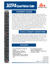
COMPRESSOREXPANDER/GATE
RATIO ATTACK
FAST
SLOW
FAST
SLOW
RELEASE OUTPUT GAIN
0
-20
-10 +10
+20
dB
THRESHOLDTHRESHOLD
-40
-20
+15
0
OFF
-60
dBu
Stereo
CoupleBypass
AutoOverEasy
-
0
+
-
+
CHANNEL ONE
THRESHOLDTHRESHOLD GAIN REDUCTION dB
1361015202530
RATIO
2:1
4:1
1:1
1.3:1
:1
-6
0
2:1
3:1
1:1 4:1
1.3:1
-10
0
+20
+10
-40
-30
-20
dBu

Note: Setting the Compressor RATIO to 1:1 will turn the Compressor off, regardless of the setting of the
Compressor THRESHOLD control and BELOW/OVEREASY/ABOVE LED status. Setting the Compressor
THRESHOLD control to +20dB will prevent all but the highest level peaks from being compressed.
OVEREASY¨ Switch
Depress this switch to select the OverEasy¨ compression characteristic. The yellow
THRESHOLD LED turns on when the signal is in the OverEasy region. When the
switch is out, the 266XL operates as a hard-knee compressor, and the yellow LED
does not light.
Compressor THRESHOLD Control and LEDs (BELOW/OVEREASY/ABOVE):
Adjust this control to set the threshold of compression from - 40dB to +20dB. In hard-
knee mode, the threshold of compression is defined as the point above which the out-
put level no longer changes on a 1:1 basis with changes in the input level.
In OverEasy mode the threshold of compression is defined as the middle of the
OverEasy threshold region, that is, Òhalf-wayÓ into compression.
The three THRESHOLD LEDs indicate the relationship of the input signal level to the
threshold of compression. The green LED lights when the signal is BELOW threshold,
the red LED lights when the signal is above threshold, and the yellow LED lights
when the OVEREASY switch is depressed and the input signal is in the OVEREASY
range.
The 266XL's OverEasy compression permits extremely smooth, natural sounding com-
pression, without artifacts, due to the gradual change of compression around the
threshold. With OverEasy compression, input signals begin to gradually activate the
266XL's internal gain change circuitry as they approach the THRESHOLD reference
level. They do not get fully processed by the RATIO, ATTACK and RELEASE con-
trols until they have passed somewhat above the THRESHOLD reference level. As the
signal level passes the THRESHOLD level, processing increases until it is fully
processed to the extent determined by the control settings.
In hard-knee mode, the 266XL can provide abrupt compression effects as well as hard-
limiting applications. Note that when in hard knee mode the yellow LED will not light
as the input signal passes across the threshold. The signal is either being compressed
(over threshold) or it is not being compressed (under threshold).
Note: Even though no input signal is being applied, it is normal for the LEDs to flicker on when the power is
applied or removed.
Compressor RATIO Control:
Adjust this control to set the amount of compression applied to the input signal.
Clockwise rotation of this control increases the compression ratio from 1:1 (no com-
pression) up to °:1 (where the compressor can be considered to be a peak limiter,
especially with faster ATTACK settings).
266XL
Compressor / Gate
COMPRESSOR SECTION
4

266XL
Com
p
ressor
/
Gate
EXPANDER/GATE SECTION
5
When an input is above the THRESHOLD setting reference level, the RATIO setting
determines the number of decibels by which the input signal must increase in level to
produce a 1dB increase in the signal level at the output of the 266XL. A setting of 2:1
indicates an input/output ratio wherein a 2dB increase in signal (above threshold) will
produce a 1dB increase in output signal. A setting of °:1 indicates that an infinite
increase in input level would be required to raise the output level by 1dB.
Compressor ATTACK and RELEASE Control:
The ATTACK control sets the amount of time it takes the 266XL to begin compress-
ing a signal once the detector has sensed a signal above threshold. The ATTACK
range is from FAST (for a tighter and more noticeable compression effect with very
little overshoot) to SLOW (for more delayed, gradual compression). A very fast
ATTACK setting will cause the 266XL to act like a peak limiter even though RMS
detection circuitry is used. Slower ATTACK settings cause the 266XL to act like an
RMS or averaging detecting compressor/limiter.
The RELEASE control sets how fast the compression circuit returns the input to its
original level. The RELEASE rate is from FAST (where compression follows the
envelope of the program material very tightly) to SLOW (for very smooth compres-
sion).
There is no absolute right way to set the ATTACK and RELEASE controls. However,
in general, you will want them set slow enough to avoid pumping or breathing
sounds caused when background sounds are audibly modulated by the dominant sig-
nal energy, yet the release must be fast enough to avoid suppression of the desired
signal after a sudden transient or loud note has decayed. For low frequency tones
(e.g., bass guitar), set RELEASE and ATTACK to 2:00 or slower.
Note: ATTACK and RELEASE controls operate together and in conjunction with the RATIO control.
Changing one control may necessitate changing another setting.
Auto Switch:
This switch overrides both the ATTACK and RELEASE controls and enables preset
program-dependent attack and release times. These times are derived from the input
signal and continuously change to match its dynamics. Enabling this AUTO Function
duplicates the Òclassic dbx soundÓ of the 266XLÕs forerunners which have become
standards in the industry.
Note: The Expander/Gate is off when the Expander/Gate THRESHOLD is set to OFF.
Expander/Gate THRESHOLD Control and LEDs (BELOW/ABOVE):
Adjusting this control sets the level at which the gate will open and allow the signal
at the input to pass through to the output. Turning the knob fully counterclockwise (to
OFF) allows the gate to pass all signals unattenuated, effectively bypassing the gate.
Turning the knob fully clockwise causes the gate to attenuate input signals below
+15dBu. The depth of attenuation depends on the setting of the Expander/Gate
RATIO control.
The two Expander/Gate LEDs indicate the relationship of the input signal level to the
threshold setting. The red LED lights when the signal is BELOW threshold, the green
LED lights when the signal is ABOVE threshold.

Expander/Gate RATIO Control:
This control sets the amount of attenuation applied to the input signal once it is below
the threshold, from gentle downward expansion (appropriate for mixed program,
vocals, etc.), to a hard gating effect (which can be useful for percussion). Fairly low
RATIO (and higher Expander/Gate THRESHOLD) settings work best for downward
expansion, whereas higher RATIO settings (clockwise towards MAX) work best for
gating. If a setting produces undesirable pumping, readjust the Expander/Gate RATIO
or THRESHOLD setting.
Note: The attack and release rate of the Expander/Gate are program-dependent - very fast for transient
material (e.g., percussion) and slower for material with slow attack (e.g., vocals).
Note: Fast gating of sustained low frequency signals can result in “chattering”. To eliminate any “chattering”
simply adjust the RATIO control. The proper THRESHOLD setting will also minimize false triggering and
“chattering.”
INPUT Jacks (CHANNEL 1 and 2):
Use 1/4Ó phone plugs or male XLR plugs to connect these inputs to your source. The
266XL's INPUT jacks accept either balanced or unbalanced signals. Input impedance
is >40k½.
OUTPUT Jacks (CHANNEL 1 and 2):
The OUTPUT jacks accept 1/4Ó balanced or unbalanced phone plugs or female XLR
plugs. Maximum output signal level is >+20dBu. In the +4dBu setting, the balanced
output impedance is 100½, and the unbalanced output impedance is 50½. In the
-10dBV setting, the balanced output impedance is 1k½ and the unbalanced output
impedance is 500½.
OPERATING LEVEL Switch
This switch selects between a -10dBV and +4dBu nominal operating level. When the
switch is in the IN position, a -10dBV operating level is selected. When it is in the
OUT position, a +4dBu operating level is selected. Note that the switch is slightly
recessed. This is to provide protection against accidental activation, possibly causing
damage to other system components due to a sudden change in gain.
SIDECHAIN INSERT Jack:
This jack accepts 1/4Ó TRS phone plugs and provides a connection to the 266XL
detector path. The RING acts as a Send, carrying a buffered version of the signal pre-
sent at the 266XL INPUT jack, at an impedance of 2k½. The TIP acts as a Return for
equipment to feed the 266XL's detector circuitry, such as an equalizer for de-essing or
frequency-sensitive gating/compression. You can also drive the 266XL Sidechain input
with the output of most equipment, by using a 1/4Ó mono phone plug. Input
Impedance is greater than 10k½.
Note: When a cable is plugged into this jack, it automatically breaks the connection from the INPUT jack to
the 266XL's detection circuitry.
266XL
Compressor / Gate
Rear Panel
6
PROFESSIONAL PRODUCTS
A HARMAN INTERNATIONAL
COMPANY
SALT LAKE CITY, UTAH
MADE IN USA
MODEL 266XL
COMPRESSOR/GATE
15 WATTS
100V 50/60Hz
120V 60Hz
SIDECHAIN
INSERT
TIP=INPUT
RING=OUTPUT
SIDECHAIN
INSERT
TIP=INPUT
RING=OUTPUT
INPUTSOUTPUTS
CHANNEL 1
+4 dBu
-10 dBV
INPUTSOUTPUTS
CHANNEL 2
+4 dBu
-10 dBV
MANUFACTURED UNDER ONE OR MORE OF THE FOLLOWING U.S. PATENTS 4,234,804 4,316,107 4,329,598 4,331,931 4,377,792 4,403,199 4,409,500 4,425,551 4,434,380 4,454,433 4,471,324 4,473,793 OTHER PATENTS PENDING
PHONE:
TIP
RING
SLEEVE
XLR:
PIN 1
PIN 2
PIN 3

IEC - AC Power cord receptacle
Plug the AC power cord (supplied) into the 266XL. Plug the other end into a standard
wall receptacle. Take care to route power cables away from audio lines. Note that the
266XL does not have a power switch. It is recommended that the 266XL be ÒOnÓ at
all times. Power consumption is low. If you do not plan to use the 266XL for an
extended period of time, unplug it.
WARNING: Be sure to verify your actual line voltage is the same as the voltage level printed
below the AC power receptacle. Connection to an inappropriate power source may result in
extensive damage which is not covered by the warranty.
Caution: Never remove the cover. There are no user-serviceable parts inside.
The 266XL can be used with any line-level device. Some common examples include
mixing consoles, electronic musical instruments, patch bays, and signal processors.
For all connections, refer to the following steps:
Turn Off all equipment before making any connections.
Mount the 266XL in a 1U rack space (optional).
The 266XL requires one rack space (height) and 1 rack space (width). It can be
mounted above or below anything that doesn't generate excessive heat, since it
requires no special ventilation. Ambient temperatures should not exceed 113¼F (45¼C)
when equipment is powered.
Make connections via 1/4Ó phone or XLR jacks according to your requirements.
Typical patch points include: a mixer's channel or subgroup inserts when using the
266XL on individual instruments or tracks; the mixer's main outputs when mixing; an
instrument preamp's effects loop when using the 266XL for guitar or bass; main outs
of a submixer (i.e., keyboard mixer) as the signal is sent to main mixer; between a
DAT's output and an analog cassette input. When using a chain of processors, the
266XL may be placed either before or after effects or dynamics processors. We rec-
ommend you use common sense and experiment with different setups to see which
one provides the best results for your needs.
Connect the AC power cord (shipped with the unit) to the 266XL's rear panel
POWER connector and an appropriate AC power source to turn the unit ON.
266XL
Com
p
ressor
/
Gate
7
CONNECTING THE 266XL TO YOUR SYSTEM

The 266XL is an all-solid-state product with components chosen for high performance
and excellent reliability. Each 266XL is tested, burned-in and calibrated at the factory
and should require no internal adjustment of any type throughout the life of the unit.
We recommend that your 266XL be returned to the factory only after referring to the
manual and consulting with dbx Customer Service.
Our phone number, Fax number and address are listed on the back cover of this manu-
al.
When you contact dbx Customer Service, be prepared to accurately describe the prob-
lem. Know the serial number of your unit. This is printed on a sticker attached to the
side panel of the unit.
Note: Please refer to the terms of your Limited Two-Year Standard Warranty, which extends to the first end-
user. After the warranty expires, a reasonable charge will be made for parts, labor, and packing if you
choose to use the factory service facility. In all cases, you are responsible for shipping charges to the facto-
ry. dbx will pay return shipping if the unit is still under warranty.
Shipping Instructions: Use the original packing material if it is available. Mark the
package with the name of the shipper, and with these words in red: DELICATE
INSTRUMENT, FRAGILE! Insure the package properly. Ship prepaid, not collect. Do
not ship parcel post.
We appreciate your feedback. After you have an opportunity to use your new 266XL,
please complete the Registration Card and return it.
266XL
Compressor / Gate
8
REGISTRATION CARD AND USER FEEDBACK
TECHNICAL SUPPORT AND FACTORY SERVICE

FRANÇAIS
266XL
Com
p
ressor
/
Gate
9

266XL
Com
p
ressor
/
Gate
11
TABLE DES MATIERES
INTRODUCTION . . . . . . . . . . . . . . . . . . . . . . . . . . . . . . . . . . . . . . . . . . . . . 12
DESCRIPTION DES CONTROLES . . . . . . . . . . . . . . . . . . . . . . . . . . . . . . . . . . 13
SECTION COMPRESSEUR . . . . . . . . . . . . . . . . . . . . . . . . . . . . . . . . . . . . . . . 14
SECTION EXPANSEUR/GAT E . . . . . . . . . . . . . . . . . . . . . . . . . . . . . . . . . . . . 15
CONNEXION DU 266XL A VOTRE SYSTEME . . . . . . . . . . . . . . . . . . . . . . . . . 17
S
UPPORT TECHNIQUE/APRéS-VENTE . . . . . . . . . . . . . . . . . . . . . . . . . . . . . .17
ENREGISTREMENT . . . . . . . . . . . . . . . . . . . . . . . . . . . . . . . . . . . . . . . . . . . 18
SPECIFICATIONS . . . . . . . . . . . . . . . . . . . . . . . . . . . . . . . . . . . . . . . . . . . . 39
SYNOPTIQUE . . . . . . . . . . . . . . . . . . . . . . . . . . . . . . . . . . . . . . . . . . . . . . . 41

DEUTSCH
266XL
Com
p
ressor
/
Gate
19

266XL
Com
p
ressor
/
Gate
21
INHALT
EINLEITUNG . . . . . . . . . . . . . . . . . . . . . . . . . . . . . . . . . . . . . . . . . . . . . . . 22
BEDIENELEMENTE . . . . . . . . . . . . . . . . . . . . . . . . . . . . . . . . . . . . . . . . . . . 23
KOMPRESSOR-SEKTION . . . . . . . . . . . . . . . . . . . . . . . . . . . . . . . . . . . . . . . 24
EXPANDER/GATE-SEKTION . . . . . . . . . . . . . . . . . . . . . . . . . . . . . . . . . . . . . 25
ANSCHLIESSEN DES DBX 266XL AN IHRE ANLAGE . . . . . . . . . . . . . . . . . . . 27
S
ERVICE UND KUNDENDIENST . . . . . . . . . . . . . . . . . . . . . . . . . . . . . . . . . . 27
REGISTRIERUNGS- UND ANTWORTKARTE . . . . . . . . . . . . . . . . . . . . . . . . . . . 28
TECHNISCHE DATEN . . . . . . . . . . . . . . . . . . . . . . . . . . . . . . . . . . . . . . . . . 39
BLOCKSCHALTBILD . . . . . . . . . . . . . . . . . . . . . . . . . . . . . . . . . . . . . . . . . . 41

ESPAÑOL
266XL
Com
p
ressor
/
Gate
29

266XL
Com
p
ressor
/
Gate
31
CONTENIDO DEL MANUAL
INTRODUCCION . . . . . . . . . . . . . . . . . . . . . . . . . . . . . . . . . . . . . . . . . . . . . 32
CONTROLES . . . . . . . . . . . . . . . . . . . . . . . . . . . . . . . . . . . . . . . . . . . . . . . 33
SECCION COMPRESSOR . . . . . . . . . . . . . . . . . . . . . . . . . . . . . . . . . . . . . . . 34
SECCION EXPANDER/GAT E . . . . . . . . . . . . . . . . . . . . . . . . . . . . . . . . . . . . 35
CONEXION DEL 266XL A SU SISTEMA . . . . . . . . . . . . . . . . . . . . . . . . . . . . . 37
A
POYO TECNICO/SERVICIO DE FABRICA . . . . . . . . . . . . . . . . . . . . . . . . . . . . 37
REGISTRO Y REACCIONES DE LOS USUARIOS . . . . . . . . . . . . . . . . . . . . . . . . 38
ESPECIFICACIONES . . . . . . . . . . . . . . . . . . . . . . . . . . . . . . . . . . . . . . . . . . 39
DIAGRAMA EN BLOQUES . . . . . . . . . . . . . . . . . . . . . . . . . . . . . . . . . . . . . . 41

266XL
Com
p
ressor
/
Gate
39
Note / Note / Anm. / Nota: 0dBu = 0.775VRMS Specifications are subject to change. / Les spŽcifications peuvent •tre modifiŽes. / Technische €nderungen vorbehalten. / Las especificaciones
est‡n sometidas a cambio.
Frequency Response / RŽponse en frŽquence / Frequenzgang / Respuesta de frecuencia
Flat 20Hz - 20kHz, +0, -0.5dB
Bandwidth 0.35Hz - 90kHz, +0, -3dB
Input (Balanced or Unbalanced) / EntrŽe (symŽtrique ou asymŽtrique) / Eingang (symmetrisch/asymmetrisch / Entrada (equilibrada o desequilibrada)
Impedance >40k½
Max Level +22dBu
Output (Impedance Balanced) / Sortie (ImpŽdance symŽtrique) / Ausgang (impedanzsymmetriert) / Salida (impedancia equilibrada)
Impedance + 4dBu: Balanced: 100½
Unbalanced: 50½
-10dBV: Balanced: 1k½
Unbalanced: 500½
Max Level >+21dBu, >+18dBm (into 600½)
Sidechain Insert / Insert Sidechain / Sidechain-Anschluss / Sidechain Insert
Input Impedance >10k½
Output Impedance 2k½
Max Input Level +22dBu
Max Output Level >+20dBu
Distortion + Noise <0.2%; any amount of compression at 1kHz
Klirrfaktor + Rauschen <0,2% bei jedem Kompressionsgrad bei 1 kHz
Distorsion + Bruit <0.2%; tout taux de compression ˆ 1kHz
Distosi—n + ruido <0,2%; cualquier cantidad de compresi—n a 1kHz
Intermodulation Distortion <0.2% SMPTE
Distorsion Intermodulation <0,2% SMPTE
Intermodulationsverzerrungen <0,2% (SMPTE)
Distorsi—n de intermodulaci—n <0,2% SMPTE
Noise <-93dB, unweighted (22kHz measurement bandwidth)
Bruit <-93dB, non pondŽrŽ (22kHz)
Rauschen <-93dB, unbewertet (22kHz Messbandbreite))
Ruido <-93dB, no ponderado (ancho de banda de misura: 22kHz )
Dynamic Range >114dB, unweighted
Dynamique >114dB, non pondŽrŽ
Dynamikbereich >114dB, unbewertet
Gama din‡mica >114dB, no ponderado
Interchannel Crosstalk <-95dB, 20Hz to 20kHz
Diaphonie <-95dB, 20Hz ˆ 20kHz
†bersprechen zwischen KanŠlen <-95dB, 20Hz bis 20kHz
Diafon’a entre los canales <-95dB, 20Hz a 20kHz
Common Mode Rejection >40dB, typically >55dB @ 1kHz
RŽjection de Mode Commun >40dB, typique >55dB @ 1kHz
GleichtaktunterdrŸckung >40dB, typisch >55dB bei 1kHz
Rechazo de modo comœn >40dB, t’pico >55dB a 1kHz
Stereo Coupling True RMS Power Summingª
Couplage StŽrŽo Sommation en Žnergie
Stereokopplung True RMS Power Summingª
Acoplamiento estŽreo True RMS Power Summingª
THRESHOLD
Compressor OverEasy¨ or hard-knee; -40 to +20dBu
Expander/Gate -60 to +10dBu
RATIO
Compressor 1:1 to Infinity:1
Expander/Gate 1:1 to 4:1
ATTACK Time
Compressor Scalable Program-Dependent AutoDynamicª
Expander/Gate <100µSec
RELEASE Time
Compressor Scalable Program-Dependent AutoDynamicª
Expander/Gate Program-Dependent
Operating Voltage
Tension
Netzspannung
Tensi—n de servicio 100VAC 50/60Hz; 120VAC 60Hz; 230VAC 50/60Hz
Power Consumption 15 Watts
Consommation
Leistungsaufnahme
Consumo de energ’a 15W
S
PECIFICATIONS
/ S
PECIFICATIONS
/ T
ECHNISCHE
D
ATEN
/ E
SPECIFICACIONES

Operating Temperature 32¡F to 113¡F
TempŽrature de fonctionnement 0¡C ˆ 45¡C
Betriebstemperatur 0¡C bis 45¡C
Temperatura de funcionamiento 0¡C a 45¡C
Dimensions (H x D x W) 1.75Ó x 5.75Ó x 19Ó
Dimensions (H x P x L)
Abmessungen (H x T x B)
Dimensiones alto x prof x ancho) 45 x 146 x 485 mm
Weight Net Weight: 4.84 lbs; Shipping Weight: 6.6 lbs
Poids Poids Net : 2,19 kg; Poids brut : 2,99 kg
Gewicht: 2,19 kg netto; 2,99 kg brutto
Peso peso neto: 2,19 kg; peso bruto: 2,99 kg
266XL
Compressor / Gate
40

266XL
Com
p
ressor
/
Gate
41
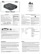
·
·
Input
RF
Filter
RF
Filter
RF
Filter
RF
Filter
Operating
Level
Select
+
-
VCA
+4dBu (out)
-10dBV (in)
RMS Level
Detector
Compressor
Control
Expander
Control
OverEasy
Sidechain
Insert
Threshold
Ratio
Attack
Release
Threshold
Below
Above
Below
Above
OverEasy
Output
Gain
Gain Reduction
Bypass
266A Block Diagram
10/22/96
(
Operating
Level
Select
Ratio

®
8760 South Sandy Pkwy.
Sandy, Utah 84070
Phone: (801) 568-7660
Fax: (801) 568-7662
IntÕl Fax: (219) 462-4596
E¥mail: [email protected]
World Wide Web: www.dbxpro.com
A Harman International Company
18-2296-B
2/19/98
/