Page is loading ...

GP-1670F/GP-1870F
OPERATOR'S MANUAL
www.furuno.com
GPS PLOTTER/SOUNDER
Model

The paper used in this manual
is elemental chlorine free.
・FURUNO Authorized Distributor/Dealer
9-52 Ashihara-cho,
Nishinomiya, 662-8580, JAPAN
A
:
JUN
2012
.
Printed in Japan
All rights reserved.
C
:
FEB
.
15, 2013
Pub. No.
OME-44770-C
*0 0017659312*
(
TAHA
)
GP-1670F/GP-1870F
*0 0017659312*
* 0 0 0 1 7 6 5 9 3 1 2 *

i
IMPORTANT NOTICES
General
• This manual has been authored with simplified grammar, to meet the needs of international us-
ers.
• The operator of this equipment must read and follow the descriptions in this manual. Wrong op-
eration or maintenance can cancel the warranty or cause injury.
• Do not copy any part of this manual without written permission from FURUNO.
• If this manual is lost or worn, contact your dealer about replacement.
• The contents of this manual and equipment specifications can change without notice.
• The example screens (or illustrations) shown in this manual can be different from the screens
you see on your display. The screens you see depend on your system configuration and equip-
ment settings.
• Save this manual for future reference.
• Any modification of the equipment (including software) by persons not authorized by FURUNO
will cancel the warranty.
• SDHC is a registered trademark of SD-3C, LLC.
• All brand and product names are trademarks, registered trademarks or service marks of their
respective holders.
How to discard this product
Discard this product according to local regulations for the disposal of industrial waste. For disposal
in the USA, see the homepage of the Electronics Industries Alliance (http://www.ei-
ae.org/) for the correct method of disposal.
How to discard a used battery
Some FURUNO products have a battery(ies). To see if your product has a battery, see the chapter
on Maintenance. Follow the instructions below if a battery is used. Tape the + and - terminals
of battery before disposal to prevent fire, heat generation caused by short circuit.
In the European Union
The crossed-out trash can symbol indicates that all types of batteries
must not be discarded in standard trash, or at a trash site. Take the
used batteries to a battery collection site according to your national
legislation and the Batteries Directive 2006/66/EU.
In the USA
The Mobius loop symbol (three chasing arrows) indicates that Ni-Cd
and lead-acid rechargeable batteries must be recycled. Take the used
batteries to a battery collection site according to local laws.
In the other countries
There are no international standards for the battery recycle symbol. The number of symbols can
increase when the other countries make their own recycle symbols in the future.
Cd
Ni-Cd Pb

ii
SAFETY INSTRUCTIONS
WARNING
WARNING
Do not open the equipment.
The equipment uses high voltage that
can cause electrical shock. Refer any
repair work to a qualified technician.
If water leaks into the equipment or
something is dropped into the equip-
ment, immediately turn off the power
at the switchboard.
Fire or electrical shock can result.
If the equipment is giving off smoke
or fire, immediately turn off the power
at the switchboard.
Fire or electrical shock can result.
If you feel the equipment is acting
abnormally or giving off strange
noises, immediately turn off the
power at the switchboard and contact
a FURUNO service technician.
Electrical current flows to the pins of
the transducer connector when the
power is on, regardless of whether
the transducer cable is connected or
not.
If the transducer cable is not connected,
cover the transducer connector with the
supplied cap to prevent electrical shock.
Mandatory Action
Prohibitive Action
WARNING
CAUTION
Warning, Caution
The operator must read the safety instructions before attempting to operate the equipment.
Indicates a potentially hazardous situation which, if not avoided,
could result in death or serious injury.
Indicates a potentially hazardous situation which, if not avoided,
could result in minor or moderate injury.
WARNING
WARNING
Do not disassemble or modify the
equipment.
Fire, electrical shock or serious injury
can result.
Make sure no rain or water splash
leaks into the equipment.
Fire or electrical shock can result if
water leaks into the equipment.
Do not place liquid-filled containers
on or near the equipment.
Fire or electrical shock can result if a
liquid spills into the equipment.
Do not operate the equipment with
wet hands.
Electrical shock can result.
Use the proper fuse.
Use of the wrong fuse can cause fire or
electrical shock.

SAFETY INSTRUCTIONS
iii
CAUTION
Do no turn on the equipment with the
transducer out of water.
The transducer can be damaged.
The picture is not refreshed when
picture advancement is stopped.
Maneuvering the vessel in this condition
can result in a dangerous situation.
Adjust the gain correctly.
Incorrect gain may give a wrong depth
indication, which could result in a
dangerous situation.
The data presented by this equipment
is intended as a source of navigation
information.
The prudent navigator never relies
exclusively on any one source of
navigation information, for safety of
vessel and crew.
The LCD panel is made of glass.
Handle it with care.
Injury can result if the glass breaks.
Follow the compass safe distances
shown below to prevent interference
to a magnetic compass.
Standard
compass
Steering
compass
GP-1670F
GP-1870F
0.30 m
0.30 m
0.30 m
0.30 m
Warning Label
Warning Label
Do not remove the label.
To avoid electrical shock,do not remove
cover. No user-serviceable parts inside.

iv
TABLE OF CONTENTS
FOREWORD ...................................................................................................................ix
SYSTEM CONFIGURATION ..........................................................................................xi
EQUIPMENT LISTS.......................................................................................................xii
1. OPERATIONAL OVERVIEW .................................................................................1-1
1.1 Controls...................................................................................................................... 1-1
1.1.1 Control description ......................................................................................... 1-1
1.2 RotoKey
TM
and Soft Controls .................................................................................... 1-5
1.3 How to Turn the Power On or Off............................................................................... 1-6
1.4 How to Adjust the Display Brilliance........................................................................... 1-6
1.5 2D Plotter Displays..................................................................................................... 1-6
1.6 The Cursor ................................................................................................................. 1-9
1.7 Navigation Data Boxes............................................................................................. 1-10
1.7.1 How to select the data to display in a box.................................................... 1-10
1.8 Home Screen (Display Selection) ............................................................................ 1-11
1.8.1 How to select a display ................................................................................ 1-11
1.8.2 How to switch the active screen................................................................... 1-11
1.8.3 How to customize the home screen............................................................. 1-12
1.8.4 Description of home screen displays ........................................................... 1-14
1.9 Display Range.......................................................................................................... 1-18
1.10 Orientation Mode...................................................................................................... 1-18
1.11 How to Move the Chart ............................................................................................ 1-19
1.12 Menu Operation ....................................................................................................... 1-20
1.13 Object Information.................................................................................................... 1-21
1.13.1 Simple information ....................................................................................... 1-21
1.13.2 Detailed information ..................................................................................... 1-21
1.14 Context-Sensitive Menus ......................................................................................... 1-22
1.15 Man Overboard (MOB)............................................................................................. 1-24
1.15.1 How to mark MOB position .......................................................................... 1-24
1.15.2 How to stop navigating to a MOB mark........................................................ 1-24
1.15.3 How to erase an MOB mark......................................................................... 1-24
1.16 How to Take a Screenshot....................................................................................... 1-24
1.17 Tide Information ....................................................................................................... 1-25
1.17.1 Tide height information................................................................................. 1-25
1.17.2 Tide stream information ............................................................................... 1-26
2. TRACK ...................................................................................................................2-1
2.1 How to Show, Hide all Track ...................................................................................... 2-1
2.2 How to Stop Recording Track .................................................................................... 2-1
2.3 How to Select Recording Method, Recording In-terval .............................................. 2-1
2.4 How to Change the Color of Your Boat’s Track ......................................................... 2-2
2.5 How to Change the Color of Your Boat’s Track with Sea Surface Temperature ....... 2-2
2.6 How to Hide, Show Track by Color ............................................................................ 2-2
2.7 How to Delete Track by Color .................................................................................... 2-3
2.8 How to Find Track Information ................................................................................... 2-3
3. POINTS ..................................................................................................................3-1
3.1 What is a Point? ......................................................................................................... 3-1
3.2 How to Enter a Point ..................................................................................................3-1
3.2.1 How to enter a point at the current position ................................................... 3-1
3.2.2 How to enter a point at the cursor position..................................................... 3-2

TABLE OF CONTENTS
v
3.2.3 How to enter a position manually on the plotter screen .................................3-3
3.2.4 How to enter a point from the Points List .......................................................3-3
3.3 How to Find Detailed Point Information......................................................................3-4
3.4 How to Move a Point ..................................................................................................3-4
3.4.1 How to move a point on the screen................................................................3-4
3.4.2 How to move a point from the Points List.......................................................3-4
3.5 How to Select Visibility for Points ...............................................................................3-5
3.6 How to Search, Sort Points on the Points List............................................................3-5
3.6.1 How to search points......................................................................................3-5
3.6.2 How to sort points...........................................................................................3-5
3.7 How to Filter Points by Shape on the Points List........................................................3-6
3.8 How to Delete Points..................................................................................................3-6
3.8.1 How to delete a point from the screen............................................................3-6
3.8.2 How to delete points from the Points List .......................................................3-6
4. ROUTES ................................................................................................................4-1
4.1 What is a Route?........................................................................................................4-1
4.2 How to Create a Route...............................................................................................4-1
4.2.1 How to create a route from the RotoKey menu ..............................................4-1
4.2.2 How to create a route from the Routes List....................................................4-2
4.2.3 How to create a route with the Easy Routing feature .....................................4-3
4.3 How to Extend a Route on the Screen .......................................................................4-6
4.4 How to Insert a Point on a Route on the Screen ........................................................4-7
4.5 How to Move a Point in a Route on the Screen..........................................................4-7
4.6 How to Delete a Point From a Route on the Screen ..................................................4-7
4.7 Routes List..................................................................................................................4-8
4.7.1 How to display the Routes List .......................................................................4-8
4.7.2 Functions available in the Routes List............................................................4-9
4.8 Route Report, Route Calculator ...............................................................................4-10
4.9 How to Display a Route on the Screen.....................................................................4-11
4.10 How to Connect Two Routes....................................................................................4-11
4.11 Simple Route Information.........................................................................................4-11
4.12 How to Rename a Route on the Screen...................................................................4-12
4.13 How to Delete Routes...............................................................................................4-12
4.13.1 How to delete a route on the screen ............................................................4-12
4.13.2 How to delete routes from the Routes List ...................................................4-12
5. NAVIGATION.........................................................................................................5-1
5.1 How to Navigate to a Quick Point...............................................................................5-1
5.2 How to Navigate to a Saved Point..............................................................................5-2
5.2.1 How to navigate to a saved point selected on the screen ..............................5-2
5.2.2 How to navigate to a point selected from the Points List................................5-2
5.3 How to Select a Route for Navigation.........................................................................5-2
5.3.1 On-screen route .............................................................................................5-2
5.3.2 Route selected from the Routes List ..............................................................5-3
5.3.3 How to start navigation from a point on a route..............................................5-3
5.4 Functions Available When You Follow a Route..........................................................5-4
5.4.1 Restart navigation ..........................................................................................5-4
5.4.2 Follow a route in reverse order.......................................................................5-4
5.4.3 Stop following a route.....................................................................................5-4
5.4.4 Skip a leg in a route........................................................................................5-4
6. MAP SETTINGS, 2D PERSPECTIVE/3D DISPLAYS AND
SATELLITE OVERLAY .........................................................................................6-1
6.1 Map Setup ..................................................................................................................6-1
6.2 2D Perspective Dispay ...............................................................................................6-5

TABLE OF CONTENTS
vi
6.3 3D Display..................................................................................................................6-6
6.3.1 3D display description.................................................................................... 6-6
6.3.2 How to tilt and rotate the 3D display .............................................................. 6-7
6.3.3 How to make the 3D view clearer .................................................................. 6-7
6.4 Satellite Photo Overlay............................................................................................... 6-8
7. FISH FINDER OPERATIONS ................................................................................7-1
7.1 How the Fish Finder Works........................................................................................ 7-1
7.2 Fish Finder Display .................................................................................................... 7-2
7.3 How to Activate the Fish Finder ................................................................................. 7-3
7.4 How to Select a Display ............................................................................................. 7-3
7.4.1 How to select a single frequency or dual frequency....................................... 7-3
7.4.2 How to select a zoom display......................................................................... 7-4
7.4.3 A-scope display.............................................................................................. 7-5
7.4.4 Bottom discrimination display......................................................................... 7-6
7.5 Automatic Fish Finder ................................................................................................ 7-8
7.5.1 How the automatic fish finder works .............................................................. 7-8
7.5.2 How to select an automatic fish finder mode ................................................. 7-8
7.5.3 How to adjust the gain in the auto mode........................................................ 7-8
7.6 Manual Fish Finder Operation.................................................................................... 7-9
7.6.1 How to select a display range ........................................................................ 7-9
7.6.2 How to shift the range .................................................................................... 7-9
7.6.3 How to adjust the gain.................................................................................. 7-10
7.6.4 How to reduce clutter ................................................................................... 7-10
7.7 Picture Advance Speed............................................................................................ 7-11
7.8 How to Reduce Interference .................................................................................... 7-12
7.9 How to Erase Weak Echoes .................................................................................... 7-12
7.10 How to Measure Depth, Time Between Locations ................................................... 7-13
7.11 How to Balance Echo Strength ................................................................................ 7-13
7.12 White Marker............................................................................................................ 7-14
7.13 White Line ................................................................................................................ 7-14
7.14 Alarms ......................................................................................................................7-14
7.14.1 How to set an alarm ..................................................................................... 7-15
7.14.2 How to select the echo signal level that triggers the fish alarm ................... 7-15
7.15 ACCU-FISH
TM
......................................................................................................... 7-16
7.15.1 Considerations for ACCU-FISH
TM
............................................................... 7-16
7.15.2 How to activate ACCU-FISH
TM
, select display information ......................... 7-17
7.15.3 Fish size correction ...................................................................................... 7-17
7.16 Water Temperature Graph ....................................................................................... 7-18
7.17 FISH FINDER Menu.................................................................................................7-19
7.18 Interpreting the Display ............................................................................................ 7-22
8. ALARMS ................................................................................................................8-1
8.1 ALARMS Menu .......................................................................................................... 8-1
8.2 Audio Alarm Conditions.............................................................................................. 8-2
8.3 Arrival Alarm...............................................................................................................8-2
8.4 XTE Alarm.................................................................................................................. 8-3
8.5 Temperature Alarm .................................................................................................... 8-3
8.6 Shear Alarm ............................................................................................................... 8-4
8.7 Depth Alarm ............................................................................................................... 8-4
8.8 Anchor Alarm ............................................................................................................. 8-5
8.9 Trip Alarm...................................................................................................................8-5
8.10 Speed Alarm .............................................................................................................. 8-5
8.11 Fuel Tank Alarm......................................................................................................... 8-6
8.12 Water Tank Alarm ...................................................................................................... 8-6
8.13 Black Water Tank Alarm ............................................................................................ 8-6

TABLE OF CONTENTS
vii
9. MEMORY CARD OPERATIONS ...........................................................................9-1
9.1 The Memory Card Screen ..........................................................................................9-1
9.2 How to Initialize SD Cards..........................................................................................9-1
9.3 How to Eject an SD Card............................................................................................9-2
9.4 How to Save Data to an SD Card...............................................................................9-2
9.5 How to Rename Files on an SD Card ........................................................................9-2
9.6 How to Delete Files from an SD Card ........................................................................9-3
9.6.1 How to delete individual files from an SD card...............................................9-3
9.6.2 How to delete all files from an SD card ..........................................................9-3
9.7 How to Import Data from an SD Card.........................................................................9-3
9.8 How to Process Screenshots .....................................................................................9-4
9.8.1 How to select source of screenshots (internal memory or SD card) ..............9-4
9.8.2 How to save screenshots in the internal memory to an SD card....................9-4
9.8.3 How to delete screenshots .............................................................................9-5
10. OTHER FUNCTIONS ..........................................................................................10-1
10.1 AIS Operations .........................................................................................................10-1
10.1.1 AIS target symbols .......................................................................................10-1
10.1.2 How to find AIS target information................................................................10-2
10.1.3 AIS activation range .....................................................................................10-2
10.1.4 CPA and TCPA alarms.................................................................................10-2
10.2 DSC Message Information .......................................................................................10-3
10.2.1 How to select a device for DSC message information .................................10-3
10.2.2 DSC message information ...........................................................................10-3
10.3 Stopwatch, Timer......................................................................................................10-4
10.4 How to Select Input, Output Data.............................................................................10-5
10.4.1 Input data .....................................................................................................10-5
10.4.2 Output data...................................................................................................10-6
10.5 Engine Display Setup (INSTRUMENTS menu)........................................................10-7
11. CUSTOMIZING YOUR UNIT ...............................................................................11-1
11.1 GENERAL Menu ......................................................................................................11-1
11.2 PLOTTER Menu .......................................................................................................11-2
11.3 SYSTEM Menu.........................................................................................................11-3
12. MAINTENANCE, TROUBLESHOOTING ............................................................12-1
12.1 Maintenance.............................................................................................................12-1
12.2 How to Replace the Fuse .........................................................................................12-2
12.3 Troubleshooting........................................................................................................12-2
12.4 GPS Status Display..................................................................................................12-4
12.5 How to Restore Defaults, Clear Memory ..................................................................12-5
12.6 System Information...................................................................................................12-6
13. INSTALLATION ...................................................................................................13-1
13.1 Installation of Display Unit ........................................................................................13-1
13.2 Installation of Antenna Unit.......................................................................................13-2
13.3 Installation or Transducers .......................................................................................13-2
13.3.1 How to mount a transducer through the hull ................................................13-2
13.3.2 Transom mount transducer ..........................................................................13-5
13.3.3 How to mount a transducer inside the hull ...................................................13-6
13.3.4 Triducer ........................................................................................................13-7
13.4 Installation of Sensors (option)...............................................................................13-12
13.4.1 Speed/temperature sensors ST-02MSB, ST-02PSB .................................13-12
13.4.2 Temperature sensors .................................................................................13-13
13.5 Wiring .....................................................................................................................13-15
13.6 Initial Settings .........................................................................................................13-19

TABLE OF CONTENTS
viii
13.6.1 INSTALLATION SETTINGS menu.............................................................13-19
13.6.2 CAN bus input/output.................................................................................13-21
APPENDIX 1 MENU TREE .......................................................................................AP-1
APPENDIX 2 ABBREVIATIONS, SYMBOLS ...........................................................AP-6
APPENDIX 3 JIS CABLE GUIDE ...........................................................................AP-11
SPECIFICATIONS .....................................................................................................SP-1
PACKING LISTS.......................................................................................................... A-1
OUTLINE DRAWINGS................................................................................................. D-1
INTERCONNECTION DIAGRAM ................................................................................ S-1
INDEX.......................................................................................................................... IN-1

ix
FOREWORD
A Word to GP-1670F, GP-1870F Owners
Congratulations on your choice of the FURUNO GP-1670F, GP-1870F GPS Plotter/Sounder. We
are confident you will see why the FURUNO name has become synonymous with quality and re-
liability.
Since 1948, FURUNO Electric Company has enjoyed an enviable reputation for innovative and
dependable marine electronics equipment. This dedication to excellence is furthered by our ex-
tensive global network of agents and dealers.
This equipment is designed and constructed to meet the rigorous demands of the marine environ-
ment. However, no machine can perform its intended function unless operated and maintained
properly. Please carefully read and follow the recommended procedures for operation and main-
tenance.
We would appreciate hearing from you, the end user, about whether we are achieving our purpos-
es.
Thank you for considering and purchasing FURUNO equipment.
Features
The GP-1670F and GP-1870F provide a totally integrated GPS receiver, color video plotter and
color fish finder. The built-in GPS receiver provides highly accurate position, course and speed
information. The fish finder presents vivid underwater images on a high quality LCD. The compact
display unit and antenna unit permit installation where space is limited.
The main features are
General
• Bright 5.7-inch (GP-1670F) or 7-inch (GP-1870F) color LCD with brilliance control.
• Excellent viewing angles, even when wearing sunglasses.
• Internal GPS receiver provides highly accurate position information (GPS, within 2.5 m, SBAS,
within 2 m).
• Customizable analog and digital displays show wind angle and speed, engine condition (speed,
temperature, oil pressure, etc.), etc.
• Large internal memory stores 30,000 track points, 30,000 points, 1,000 routes (500 waypoints/
route).
• SD card slot accepts SD and SDHC cards for external storage of data and settings.
• Full range of alarms: Arrival, Anchor Watch, Cross-track Error, Speed, Depth, Temperature,
Fish Alarm, Bottom Alarm, etc.
• Man overboard (MOB) feature records latitude and longitude coordinates at the time of MOB.
• CAN bus interface for the connection of GPS Receiver, Weather Station, FI-50 (instrument se-
ries), Satellite Compass, etc.
• Accepts NMEA0183 input with optional NMEA data converter.
• Internal GPS antenna available.
• C-Map 4D charts available.

FOREWORD
x
Fish finder
• Fish finder measures the depth to the bottom and displays underwater conditions in multi-col-
ors* according to echo strength. A monochrome presentation shows the echoes in shades of
gray. (*Number of colors depends on network sounder, color sounder.).
• Automatic and manual fish finder operation. Auto mode automatically adjusts range, gain and
clutter ac-cording to purpose - fishing or cruising.
• Wide variety of zoom modes for detailed observation of fish and bottom.
• ACCU-FISH
TM
provides length and depth of individual fish. Appropriate transducer required.
Other
• AIS function (requires connection to an AIS transponder) provides navigational information from
AIS transponder equipped vessels within 50 nm.
• Instrument displays (steering, engine, weather, and wind) with connection of relevant sensors.
• DSC (Digital Selective Calling) function alerts to DSC messages received and position re-
quests. (Requires DSC capable radiotelephone.)
Open Source Acknowledgement
This product makes use of the following open source software:
FreeType (www.freetype.org)
Portions of this software are copyright ©2009 The FreeType Project
(www.freetype.org). All rights reserved.
libpng (http://www.libpng.org/)
This software is based in part on the work of the Independent JPEG Group.
libjpeg (http://www.ijg.org/)
We would like to thank each developer of the above-mentioned open
source software for their great contribution to the open source community.

xi
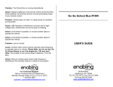
SYSTEM CONFIGURATION
The environmental category of each unit is as follows:
GP-1670F
GP-1870F
Unit Environmental category
Display unit Protected from the weather
GPS antenna unit Exposed to the weather, or protected from the weather in
case of internal antenna
Transducer, sensor Submerged in water
Other units Protected from the weather
OR
Display Unit
GP-1670F
Antenna Unit
GPA-017 or
GPA-017S
CAN bus
equipment
NMEA 0183
equipment
Junction Box
FI-5002
NMEA Data
Converter
IF-NMEA2K2
Internal GPS
antenna
Water temp./speed sensor
ST-02MSB, ST-02PSB
Water temp. sensor
T-02MSB, T-02MTB, T-03MSB
520-5PSD, 520-5MSD,
525-5PWD, 525STID-MSD,
525STID-PWD
Transducer
Matching Box
MB-1100*
* For connection to 1 kW
transducer (50B-6, 50B-6B,
200B-5S, 50/200-1T,
50/200-12M)
12-24 VDC
100/110/
220/230 VAC,
1ø, 50/60 Hz
Rectifier
PR-62
Display Unit
GP-1870F
Antenna Unit
GPA-017 or
GPA-017S
OR
Water temp./speed sensor
ST-02MSB, ST-02PSB
Water temp. sensor
T-02MSB, T-02MTB, T-03MSB
520-5PSD, 520-5MSD,
525-5PWD, 525STID-MSD,
525STID-PWD
Transducer
Matching Box
MB-1100*
* For connection to 1 kW transducer
(50B-6, 50B-6B, 200B-5S,
50/200-1T, 50/200-12M)
12-24 VDC
CAN bus
equipment
NMEA 0183
equipment
100/110/
220/230 VAC,
1ø, 50/60 Hz
Junction Box
FI-5002
NMEA Data
Converter
IF-NMEA2K2
Rectifier
PR-62
Internal GPS
antenna

xii
EQUIPMENT LISTS
Standard supply
Optional equipment
Name Type Code no. Qty Remarks
Display Unit GP-1670F - Select
one
Display Unit GP-1870F -
Installation
Materials
CP14-07100 000-021-070 1 set w/CP14-07101, MJ-A3SPF0013A-
035C (power cable)
Spare Parts SP14-03501 001-184-710 1 set
Accessories FP14-03001 001-184-730 1 set For GP-1670F
FP14-03201 001-183-120 1 set For GP-1870F
Name Type Code no. Remarks
Replacement Kit OP14-72 001-184-750
Waterproofing Cap LTWCAP-WBDMMSA1 000-167-169-11
Antenna Unit GPA-017
Antenna Unit GPA-017S
Mast Mtg. Kit CP20-01111 004-365-780
Antenna Cable Set CP20-01700 *30M* 004-372-110
Antenna Cable Set CP20-01710 *50M* 004-372-120
Transducer 520-5PSD 000-015-204 Thru-hull mount, plastic
520-5MSD 000-015-212 Thru-hull mount, metal
525-5PWD 000-146-966-01 Transom mount, plastic
Triducer (transducer
with speed/ temper-
ature sensor)
525STID-MSD 000-011-783 Thru-hull mount, metal
525STID-PWD 000-011-784 Transom mount, plastic
Transducer (1 Kw) 50B-6 000-015-042 10 m, 1 kW
50B-6B 000-015-043 15 m, 1 kW
200B-5S 000-015-029 10 m, 1 kW
50/200-1T 000-015-170 10 m, 1 kW
50/200-12M 000-015-171 10 m, 1 kW
Speed/ Tempera-
ture Sensor
ST-02MSB 000-137-986-01 Thru-hull type, metal
ST-02PSB 000-137-987-01 Thru-hull type, plastic

EQUIPMENT LISTS
xiii
Temperature Sen-
sor
T-02MTB 000-040-026 Transom mount, 8 m cable
T-02MSB 000-040-040 Thru-hull type
T-03MSB 000-040-027 Thru-hull type, 8 m cable
Matching Box MB-1100 000-041-353 For connection to 1 kW trans-
ducer
Rectifier PR-62 000-013-484 100 VAC
Rectifier PR-62 000-013-485 110 VAC
Rectifier PR-62 000-013-486 220 VAC
Rectifier PR-62 000-013-487 230 VAC
Junction Box FI-5002
Right Angle Mount-
ing Base
No.13QA330 001-111-910-10
L-angle Mounting
Base
No.13-QA310 001-111-900-10
Handrail Mounting
Base
No.13-RC5160 001-111-920-10
Cable Assy. TNC-PS-/PS-3D-L15M-R 001-173-110-10
Cable Assy. M12-05BM+05BF-010 001-105-750-10 w/connectors (light), 1 m
Cable Assy. M12-05BM+05BF-020 001-105-760-10 w/connectors (light), 2 m
Cable Assy. M12-05BM+05BF-060 001-105-770-10 w/connectors (light), 6 m
Cable Assy. M12-05BFFM-010 001-105-780-10 w/connectors (light), 1 m
Cable Assy. M12-05BFFM-020 001-105-790-10 w/connectors (light), 2 m
Cable Assy. M12-05BFFM-060 001-105-800-10 w/connectors (light), 6 m
Cable Assy. CB-05PM+05BF-010 000-167-968-10 w/connectors (heavy), 1 m
Cable Assy. CB-05PM+05BF-020 000-167-969-10 w/connectors (heavy), 2 m
Cable Assy. CB-05PM+05BF-060 000-167-970-10 w/connectors (heavy), 6 m
Cable Assy. CB-05BFFM-010 000-167-971-10 w/connectors (heavy), 1 m
Cable Assy. CB-05BFFM-020 000-167-972-10 w/connectors (heavy), 2 m
Cable Assy. CB-05BFFM-060 000-167-973-10 w/connectors (heavy), 6 m
Micro T-connector SS-050505-FMF-TS001 000-168-603-10 Micro style: 3
Mini/Micro T-con-
nector
NC-050505-FMF-TS001 000-160-507-10 Mini style: 2, micro style: 1
Termination Resis-
torr (Mini)
LTWMN-05AMMT-
SL8001
000-160-508-10 Mini style, male, termination
resistor
Termination Resis-
tor (Micro)
LTWMC-05BMMT-
SL8001
000-168-604-10 Micro style, male, termination
resistor
Name Type Code no. Remarks

EQUIPMENT LISTS
xiv
Termination Resis-
tor (Mini)
LTWMN-05AFFT-
SL8001
000-160-509-10 Mini style, female, termina-
tion resistor
Termination Resis-
tor (Micro)
LTWMC-05BFFT-
SL8001
000-168-605-10 Micro style, female, termina-
tion resistor
Inline Terminator FRU-0505-FF-IS 001-077-830-10
Cable Assy. 02S4147-1 000-141-082 For speed/temp. sensor
Inner Hull Kit 22S0191 000-082-598 w/installation instructions,
not usable with the bottom
discrimination display
NMEA Data Con-
verter
IF-NMEA2K2
Name Type Code no. Remarks

1-1
1. OPERATIONAL OVERVIEW
1.1 Controls
1.1.1 Control description
The controller for this system is either the GP-1670F or the GP-1870F. A key that has
two text labels has two functions. The top label is the main function and the bottom
label is the secondary function. Short-push to access the main function and long-push
(approximately three seconds) to access the secondary function.
You operate the chart plotter with
• Keys
• CursorPad
• RotoKey
TM
• Menus, where you select options
• Context-sensitive menus, where you select options
• Lists, where you can edit items
When you operate a key, a single beep sounds to tell you correct operation. If you do
not need the key beep, you can deactivate it from the menu.
Pictured: GP-1870F
Control Description
POWER/
BRILL key
Short press: Adjust LCD brilliance.
Long press: Turn the power on or off.
POWER/BRILL key
RotoKey
TM
ENT key
ESC/MENU key
EVENT/MOB key
POINTS/GO TO key
HOME/CTRL key
CursorPad
Behind cover:
- SD card slot
- USB micro connector
- RESET button
How to remove the hard cover
Put fingers under notch at bottom
of cover and pull toward you.

1. OPERATIONAL OVERVIEW
1-2
SD cards
The SD cards store ship’s tracks, routes, points, settings, etc. The unit
accepts SD and SDHC (Secure Digital High Capacity) type cards and
the maximum capacity is 32 GB.
To set a card in the slot, insert the card label side up. If the card does not go in easily,
do not use force. Push the card until the card is in position.
To remove a card, Select [Eject SD card] from the full RotoKey menu.
Remove the card (with your fingers) after the message "You can eject SD card safely."
appears.
Care and handling of SD cards
• Handle the cards carefully; rough handling can damage the card and destroy its
contents.
• Make sure the cover is closed at all times. Insert the card fully or remove the
card; the cover cannot be closed if the card is inserted partially.
• Remove a card with only your fingers. Do not use metal instruments (like tweezers)
to remove the card.
• Do not remove a card during the reading of the card or writing to the card, to prevent
damage to the card and loss of the data stored on the card.
• If water is at the bottom of the cover, DO NOT open the cover. Remove the water
with a dry cloth completely and then open the cover.
RotoKey
TM
Short push: Display the base RotoKey soft controls for the current
mode.
Long push: Display the full RotoKey soft controls for the current mode.
Rotate: Zoom in or out the display range for the chart. Select a menu
item. Select the display range for the fish finder.
POINTS/GO
TO key
Short press: Put a point at the cursor position.
Long press: Set cursor position as destination.
EVENT/
MOB key
Short press: Put a point at the current position.
Long press: Put an MOB (ManOverBoard) mark at current position.
ENT key Confirm current operation.
ESC/MENU
key
Short press: Escape from current operation. Silence an audio alarm.
Long press: Open the menu.
HOME/
CTRL key
Short press: DIsplay the home screen, to select a display.
Long press: Switch the active display in combination modes.
CursorPad Moves the cursor and scrolls the screen, in the direction of the arrow
pressed.
SD card slot: Card drive for SD card (chart card and memory card).
Micro USB connector: Connects to a PC for maintenance. (Mouse or USB flash mem-
ory cannot be connected.)
RESET button: Resets the program. Should the screen freeze press this button to re-
start.
Control Description

1. OPERATIONAL OVERVIEW
1-3
Tested SD cards
The SD cards tested for use in this equipment are listed in the table below.
Maker, Type Size
2 GB 4 GB 8 GB 16 GB 32 GB
ADTEC
AD-SDH (SD) [AD-SDH2G] Y
BUFFALO
RSDC-S (SD) [RSDC-S2G] Y
RSDC-G Hi-Performance (SD) [RSDC-G2G] Y
Hagiwara System
T series (SD) [PSDB0487A] Y
M series Super High Speed (SD) [PSDB0486A] Y
I-O DATA
I-O DATA (SD) [SD-2G] Y
I-O DATA Super High Speed (SD) [SDP-2G] Y
Kingston
Kingston (SD) [SD/2GBFE] Y
Kingston (SDHC) CLASS 4 [SD4/16GB] Y
Kingston (SDHC) CLASS 4 [SD4/32GB] Y
Panasonic
Panasonic PRO HIGH SPEED (SD) [RP-SDK02GJ1A] Y
Panasonic HIGH SPEED (SD) CLASS 2
[[RP-SDR02GJ1A]
Y
Panasonic HIGH SPEED (SDHC) CLASS 4
[RP-SDM04GK1K]
Y
Panasonic HIGH SPEED (SDHC) CLASS 4
[RP-SDM08GK1K]
Y
Panasonic HIGH SPEED (SDHC) CLASS 4
[RP-SDM16GK1K]
Y
Panasonic (SDHC) CLASS 4 [RP-SDP16GJ1K] Y
Panasonic (SDHC) CLASS 10 [RP-SDW16GJ1K] Y
Panasonic PRO HIGH SPEED (SDHC) CLASS 6
[RP-SDV04GK1K]
Y
Panasonic PRO HIGH SPEED (SDHC) CLASS 6
[RP-SDV08GK1K]
Y
pqi
pqi (SD) [QSDS-2G] Y

1. OPERATIONAL OVERVIEW
1-4
2 GB 4 GB 8GB 16 GB 32GB
San Disk
SanDisk (SD) [SDSDB-2048-J60] Y
SanDisk (SDHC) [SDSDBR-4096-J85] Y
SanDisk Ultra II (SDHC) CLASS 4 [SDSDRH-8192-903] Y
SanDisk Ultra II (SD) [SDSDH-2048-903] Y
SanDisk Ultra II (SDHC) [SDSDRH-4096-903] Y
SanDisk Extreme III (SDHC) [SDSDRX3-4096-903] Y
SanDisk Extreme (SDHC) [SDSDX3-016G-J31A] Y
SanDisk Extreme (SDHC) [SDSDX3-032G-J31A] Y
SILICON POWER
(SDHC) [SP016GBSDH006V10] Y
(SDHC) [SP032GBSDH006V10] Y
TOSHIBA
(SD) CLASS 4 [SD-B002GT4] Y
Maker, Type Size
/