
*988-12330-001*
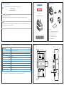
Dimensions
Parts included
Compliance statements
116 mm (4.57")
132,5 mm
(5.22")
98 mm
(3.85")
100 mm
(3.93")
47 mm
(1.85")
53 mm
(2.1")
152 mm (5.98")
92 mm
(3.62")
A. PSI-1
B. Self-tapping screws, #10 x 3/4 (4x)
C. Fuse (3 A) and fuse holder
D. Power cable, 2 m (6.6 ft)
E. Ethernet cable. 1,8 m (6 ft)
F. Documentation
PSI-1
Installation Guide
Technical specications
Environmental
Operating temperature -15°C to +55°C (5°F to 131°F)
IP class IP67
Electrical
Power supply 12/24 V DC
Operating voltage 10.8 V DC - 31.2 V DC
Current drain Transducer dependent. Max current drain with transducer connected: 1.5A at 13.8 V
Reverse polarity protection Yes
Fuse rating 3 A
Physical
Weight 0,45 kg (1 lbs.)
Compatible transducers * LiveSight
The relevant Declaration of conformity is available in the product’s section at:
www.lowrance.com
www.simrad-yachting.com
¼ Note: The most up-to-date list of compatible transducers is available at the product web site.
¼ Note: The most up-to-date specications are available at the product web site.
A
B
C
F
D
E
This product complies with:
• CE under EMC Directive 2014/30/EU
• the requirements of level 2 devices of the Radio communications (Electromagnetic Compatibility) standard 2017
Warning
The user is cautioned that any changes or modications not expressly approved by the party responsible for compliance could
void the user’s authority to operate the equipment.

Power connection
LED indicators
Wiring examples
Grounding
Power controlled by external switch Power controlled by Multi-Function Display
Switch
12 / 24 V DC
+
_
Red
Black
Yellow
Blue
Blue
(n/c)
Blue
(n/c)
Red
Black
Yellow Red
Black
Yellow
+
_
Power
Control bus
To Multi-Function
Display
12 / 24 V DC
B CA
A. Transducer cable. 7,6 m (25 ft)
B. PSI-1 to MFD cable. 1,7 m (5.6 ft)
C. Ethernet cable. 1,8 m (6 ft)
D. Power cable. 2 m (6.6 ft)
E. 9 to 7 pin adapter cable. 0,6 m (2 ft).
part no 000-13977-001. *
* Not included with PSI-1
It is recommended to ground the unit.
A. Phillips M4-0.7 x 6 mm, stainless steel
B. 1.3 mm (16 AWG) wire
A. Transducer (XDCR)
B. Status
C. Power (PWR)
LED STATUS
Description
A B C
O O Red
Power connector inserted, but no power
on yellow wire
Red
Red/
Green
Green
• No transducer connected
• Wrong transducer type connected
Red/
Green
Red Green
• Input voltage too low
• Error on output voltage to transducer
Green Green Green OK
Mounting
A
B
Material #10 screw
Soft materials e.g. plywood Ø 3.7-4.0 mm (5/32”)
Hard materials e.g. berglass, acrylic, hardwoods Ø 4.1-4.7 mm (3/16”)
Aluminum Ø 4.2-4.5 mm (0.173”)
Recommended pilot holes for self-tapping screws:
A
C
B
D
E
12/24 V DC
ETHERNET SONARETHERNET SONAR1
NSS EVO3
Transducer
PSI-1
HDS
CARBON
-
 1
1
-
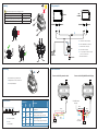 2
2


Ask a question and I''ll find the answer in the document
Finding information in a document is now easier with AI
Related papers
-
Real Cable 000-10771-001 User manual
-
-
Lowrance HDS Gen3 Installation guide
-
Lowrance HDS-12 Owner's manual
-
Lowrance StructureScan HD Module Installation guide
-
Lowrance HDS Carbon Installation guide
-
Lowrance STRUCTURESCAN-HD Owner's manual
-
-
-
Other documents
-
Simrad NSE8, NSE12 Multi Function Display Installation guide
-
-
-
-
Simrad NSS evo3S Installation guide
-
Simrad NSS evo3 Installation guide
-
-
Furuno TZT9F Installation guide
-
WIKA CPC8000 Operating instructions
-
Furuno TZTL12F Installation guide