
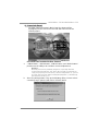
865G Mirco 775 / 865GV Micro 775
Setup Manual
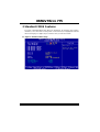
FCC Information and Copyright
This equipment has been tested and found to comply with the limits of a Class
B digital device, pursuant to Part 15 of the FCC Rules. These limits are designed
to provide reasonable protec tion against harmful interference in a residential
installation. This equipment generates, uses and can radiate radio frequency
energy and, if not installed and used in accordance with the instructions, may
cause harmful interference to radio communications. There is no guarantee
that interference will not occur in a particular ins talla tion.
The ve ndor makes no representatio ns or warranties with respec t to the
contents here and specially disclaims any implied warranties of merchantability
o r fi tness fo r a ny purpos e . F u rthe r t he ve ndo r rese rves t he ri ght to rev ise t his
publication and to make changes to the contents here without obligation to
notify any party beforehand.
D uplica tion of this publication, in part or in whole, is not allowed without first
obtaining the vendor’s approval in writing.
The content of this user’s manual is subject to be changed without notice and
we will not be res ponsible for any mistakes found in this user’s manual. All the
brand and product names are trademarks of their respective companies.

Table of Contents
Chapter 1: Introduction .............................................1
1.1 Before You Start...................................................................1
1.2 Package Checklist................................................................1
1.3 Motherboard Features..........................................................2
1.4 Rear Panel Connectors.......................................................... 3
1.5 Motherboard Layout of 865G Micro 775.................................. 4
1.6 Motherboard Layout of 865GV Micro 775................................ 5
Chapter 2: Hardware Installation..............................6
2.1 Installing Central Processing Unit (CPU)................................6
2.2 FAN Headers........................................................................8
2.3 Installing System Memory......................................................9
2.4 Connectors and Slots............................................................11
Chapter 3: Headers & Jumpers Setup .....................14
3.1 How to Setup Jumpers..........................................................14
3.2 Detail Settings.....................................................................14
Chapter 4: Useful Help .............................................20
4.1 Driver Installation Note .......................................................20
4.2 Award BIOS Beep Code........................................................21
4.3 Extra Information................................................................21
4.4 Troubleshooting...................................................................23
Chapter 5: WarpSpeeder™ .......................................24
5.1 Introduction........................................................................24
5.2 System Requirement............................................................24
5.3 Installation.........................................................................25
5.4 WarpSpeeder™....................................................................26
Appendencies: SPEC In Other Language ................32
German................................................................................................32
France..................................................................................................34
Italian..................................................................................................36
Spanish................................................................................................38
Portuguese...........................................................................................40
Polish...................................................................................................42
RUSSIAN...............................................................................................44
ARABIC................................................................................................46
JAPANESE............................................................................................48

865G Micro 775 & 865GV Micro 775
1
CHAPTER 1: INTRODUCTION
1.1 BEFORE YOU START
Tha nk yo u for choosing our pro duct. Be fore you start installing the
mo the rboa rd, plea se make sure you fo llow the instructions be lo w:
Prepare a dry and stable working environment with
s ufficie nt ligh ting .
Always disconnect the computer from power outlet
be fo re ope ra tion.
Befo re you take the mo the rboa rd ou t f rom a n ti -s ta tic
bag, ground yourself properly by touching any safely
grounde d appliance, o r use gro unded wrist strap to
remove the static charge.
Avo id tou ch ing the compone nts o n mo the rboa rd o r the
rear side of the board unless necessary. Hold the board
on the edge, do not try to be nd or flex the board.
Do not lea ve any unfastene d sma ll parts inside the
case after installation. Loose parts will cause short
circuits which ma y damage the equipment.
Keep the computer from dangerous area, such as heat
source , humid air and wa te r.
1.2 PACKAGE CHECKLIST
FDD Cable X 1
HDD Cable X 1
Rear I/O Panel for ATX Case X 1
Use r’s Manual X 1
Fully Setup Driver CD X 1
Se ria l ATA Cab le X 1 (op tiona l)
Se ria l ATA Po we r Cab le X 1 (o ptio nal)
USB 2.0 Cable X1 (optional)
S/P DI F ou t Ca ble X 1 (op tiona l)

Motherboard Manual
2
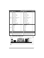
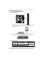
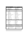
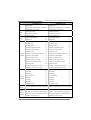
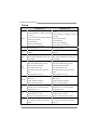
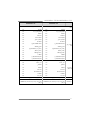
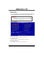
1.3 MOTHERBOARD FEATURES
865G Micro 775 865GV Micro 775
CPU
LGA 775
Intel Pentium 4 / Pentium D / Celeron D
processor up to 3.4 GHz
Intel Core2Duo Processor (For Ver 8.x only)
Supports Hyper-Threading
Execute Disable Bit
Enhanced Intel SpeedStep
Extended Memory 64 Technology
LGA 775
Intel Pentium 4 / Pentium D / Celeron D
processor up to 3.4 GHz
Supports Hyper-Threading
Execute Disable Bit
Enhanced Intel SpeedStep
Extended Memory 64 Technology
FSB 533 / 800 MHz 533 / 800 MHz
Chipset
Intel 865G
Intel ICH5
Intel 865GV
Intel ICH5
Graphics
Intel Extreme Graphics 2
Max Shared Video Memory is 64MB
Intel Extreme Graphics 2
Max Shared Video Memory is 64MB
Super I/O
ITE IT8712F
H/W Monitor
Fan Speed Controller
ITE's "Smart Guardian" function
ITE IT8712F
H/W Monitor
Fan Speed Controller
ITE's "Smart Guardian" function
Main
Memory
DIMM Slots x 2
Eac h DIMM supports 128/256/512MB & 1GB
DDR
Max Memory Capicity 2GB
Dual Channel Mode DDR memory module
Supports DDR 266 / 333 / 400
DIMM Slots x 2
Eac h DIMM supports 128/256/512MB & 1GB
DDR
Max Memory Capicity 2GB
Dual Channel Mode DDR memory module
Supports DDR 266 / 333 / 400
IDE
Integrated IDE Controller
Ultra DMA 33~100 Bus Master Mode
supports PIO Mode 0~4,
Integrated IDE Controller
Ultra DMA 33~100 Bus Master Mode
supports PIO Mode 0~4,
SA TA
Integrated Serial ATA Controller
Data transfer rates up to 1.5 Gb/s.
SATA Version 1.0 specification compliant.
Integrated Serial ATA Controller
Data transfer rates up to 1.5 Gb/s.
SATA Version 1.0 specification compliant.
10/100 LAN
Realtek RTL 8100C
10 / 100 Mb/s auto negotiation
Half / Full duplex capability
Realtek RTL 8100C
10 / 100 Mb/s auto negotiation
Half / Full duplex capability
Sound
Codec
ALC655 / 658
5.1 channels audio out
AC’97 Vers ion 2.3
ALC655 / 658
5.1 channels audio out
AC’97 Vers ion 2.3
AGP 8X graphics slot x1 XGP graphics slot x1
Slots
PCI s lot x3 PCI s lot x3

865G Micro 775 & 865GV Micro 775
3
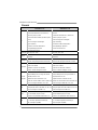
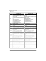
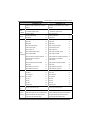
865G Micro 775 865GV Micro 775
Floppy connector x1 Floppy connector x1
IDE Connector x2 IDE Connector x2
SA TA C onnect or x2 SATA C onnect or x2
Front Panel Connector x1 Front Panel Connector x1
Front Audio Connector x1 Front Audio Connector x1
CD-in Connec tor x1 CD-in Connec tor x1
S/PDIF in connector (optional) x1 S/PDIF in connector (optional) x1
S/PDIF out connector x1 S/PDIF out connector x1
CPU Fan header x1 CPU Fan header x1
Sys tem Fan header x1 Sys tem Fan header x1
Clear CMOS header x1 Clear CMOS header x1
USB connector x2 USB connector x2
Power Connector (20pin) x1 Power Connector (20pin) x1
On Board
Connector
Power Connector (4pin) x1 Power Connector (4pin) x1
Back Panel
I/O
PS/2 Keyboard x1
PS/2 Mouse x1
S e ri a l Po rt x 1
Printer Port x1
VGA port x1
LAN port x1
USB Port x4
Audio Jack x3
PS/2 Keyboard x1
PS/2 Mouse x1
S e ri a l Po rt x 1
Printer Port x1
VGA port x1
LAN port x1
USB Port x4
Audio Jack x3
Board Size 215 (W) x 235 (L) mm 215 (W) x 235 (L) mm
OS Support
Windows 2000 / XP
Biostar Reserves the right to add or remove
support for any OS with or without notice.
Windows 2000 / XP
Biostar Reserves the right to add or remove
support for any OS with or without notice.
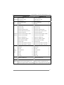
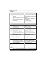
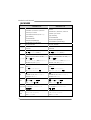
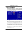
1.4 REAR PANEL CONNECTORS
VGA1
PS/2
Mouse
PS/2
Keyboard
Printer Port
COM1 USBX2USBX2
LAN
Line In/
Surround
Line Out
Mic In 1/
Bass/ Center

Motherboard Manual
4
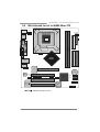
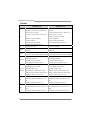
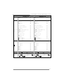
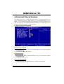
1.5 MOTHERBOARD LAYOUT OF 865G MICRO 775
LGA775
CP U1
C
O
M
1
JPRNT1
JC OM1
BIO S
ICH5
Codec
A
GP1
PCI1
PC I 2
PC I 3
SATA2
SATA1
JSFAN1
LAN
JATXPWR1
JC FAN 1
J US BV3
_
4
(
o
p
tional
)
JU SB3JU SB2
JCDIN1
JAUDIO2
JKBMS1
JUSB1
JATX PWR 2
JA U D IO 1
JVGA1
JUSBLAN1
J USB V2
(optional)
JS PD IF _OU T 1
DDRA1
Intel
865G
J PANEL1
JCMOS1
(Optional)
JSPDIF_IN1
BAT1
IDE2
IDE1
FD D1
JATX PWR 2
(Fo r all the other versions.)
(For Ver. 8.x.)
Note: represents the 1■
st
pin.

865G Micro 775 & 865GV Micro 775
5
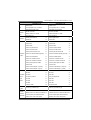
1.6 MOTHERBOARD LAYOUT OF 865GV MICRO 775
LGA775
CP U1
COM1
JPRNT1
JC OM1
BIO S
ICH5
Code c
XGP1
PCI1
PC I2
PC I3
SATA2
SATA1
JSFAN1
LAN
JATXPWR1
JC FAN 1
JU SB3JU SB2
JCDIN1
JAUDIO2
JKBMS1
JUSB1
JATX PWR 2
JA U D IO 1
JVGA1
JUSBLAN1
JS PD IF _OU T 1
DDRA1
Intel
865GV
J PANEL1
JCMOS1
(Optional)
JSPDIF_IN1
BAT1
IDE2
IDE1
FD D1
Note: represents the 1■
st
pin.

Motherboard Manual
6
CHAPTER 2: HARDWARE INSTALLATION
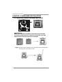
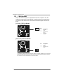
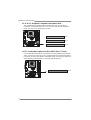
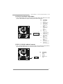
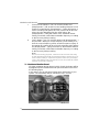
2.1 INSTALLING CENTRAL PROCESSING UNIT (CPU)
Special Notice:
Remove Pin Cap before installation, and make good preservation
for future use. When the CPU is removed, cover the Pin Cap on the
empty socket to ensure pin legs won’t be damaged.
Pin Cap
Step 1: Pull the socket locking lever out from the socket and then raise
the lever up to a 90-degree angle.

865G Micro 775 & 865GV Micro 775
7
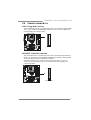
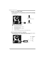
Step 2: Look for the triangular cut edge on socket, and the golden dot on
CPU should point forwards this triangular cut edge. The CPU will
fit only in the correct orientation.
Step 2-1:
Step 2-2:
Step 3: Hold the CPU down firmly, and then lower the lever to locked
position to complete the installation.
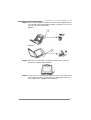
Step 4: Put the CPU Fan and heatsink assembly on the CPU and buckle it
on the retention frame. Connect the CPU FAN power cable into
the JCFAN1. This completes the installation.

Motherboard Manual
8
2.2 FAN HEADERS
These fan headers support cooling-fans built in the computer. The fan
cable and connector may be different according to the fan manufacturer.
Connect the fan cable to the connector while matching the black wire to
pin#1.
JCFAN1: CPU Fan Header
Pin
Assignment
1 Ground
2 +12V
3
FAN RPM rate
sense
JCFAN1
14
4 Smart Fan
Control
JSFAN1: System Fan Header
Pin
Assignment
1 Ground
2 +12V
JSFAN1
13
3 FAN RPM rate
sense
Note:
The JSFAN1 support 3-pi n head connector. When connecti ng with wires onto connectors,
please note that the red wire is the positive and should be connected to pin#2, and the
black wire is Ground and should be connected to GND.

865G Micro 775 & 865GV Micro 775
9
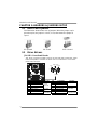
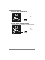
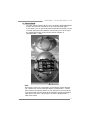
2.3 INSTALLING SYSTEM MEMORY
A. Memory Modules
DDRB1
DDRA1
1. Unlock a DIMM slot by pressing the retaining clips outward. Align a
DIMM on the slot such that the notch on the DIMM matches the
break on the Slot.
2. Insert the DIMM vertically and firmly into the slot until the retaining
chip snap back in place and the DIMM is properly seated.
B. Memory Capacity
DIMM Socket
Location
DDR Module Total Memory Size
DDRA1 256MB/512MB/1GB *1
DDRB1 256MB/512MB/1GB *1
Max is 2GB.

Motherboard Manual
10
C. Dual Channel Memory installation
To trigger the Dual Channel function of the motherboard, the memory module
must meet the following requirements:
Install memory module of the same density in pair, shown in the following table.
Dual Channel Status
DDRA1
DDRB1
Disabled O X
Disabled X O
Enabled O O
(O means memory installed, X means memory not installed.)
The DRAM bus width of the memory module must be the same (x8 or
x16)

865G Micro 775 & 865GV Micro 775
11
2.4 CONNECTORS AND SLOTS
FDD1: Floppy Disk Connector
The motherboard provides a standard floppy disk connector that supports 360K,
720K, 1.2M, 1.44M and 2.88M floppy disk types. This connector supports the
provided floppy drive ribbon cables.
34 33
12
IDE1/IDE2: Hard Disk Connectors
The motherboard has a 32-bit Enhanced PCI IDE Controller that provides PIO
Mode 0~4, Bus Master, and Ultra DMA 33/66/100 functionality. It has two HDD
connectors IDE1 (primary) and IDE2 (secondary).
The IDE connectors can connect a master and a slave drive, so you can
connect up to four hard disk drives. The first hard drive should always be
connected to IDE1.
IDE2 IDE1
21
3940

Motherboard Manual
12
PCI1~PCI3: Peripheral Component Interconnect Slots
This motherboard is equipped with 3 standard PCI slots. PCI stands for
Peripheral Component Interconnect, and it is a bus standard for expansion
cards. This PCI slot is designated as 32 bits.
PCI3
PCI2
PCI1
AGP1: Accelerated Graphics Port Slot ( 865G Micro 775 only )
Your monitor will attach directly to that video card. This motherboard supports
video cards for PCI slots, but it is also equipped with an Accelerated Graphics
Port (AGP). An AGP card will take advantage of AGP technology for improved
video efficiency and performance, especially with 3D graphics.
A
GP

865G Micro 775 & 865GV Micro 775
13
XGP1: Xtreme Graphics Port Slot ( 865GV Micro 775 only )
This XGP (Extreme Graphics Port) slot is a special design that only supports
compatible AGP VGA cards.
To install the system with an add-on AGP VGA card, please make sure to install
the driver of add-on AGP VGA card before onboard VGA driver installation. If the
onboard VGA driver has already been installed before you install the add-on
AGP VGA card, the system will automatically set the onboard VGA as the
primary graphics adapter.
For the onboard VGA driver can’t be removed completely, and to solve this
problem, please follow the steps below,
1. Disable onboard VGA utility under the operating system, and reboot PC. After
PC restarts, the system will automatically set the AGP VGA card as the
graphics adapter.
2. Or, re-install your operating system to ensure the AGP VGA card function can
be used.
Note:
Please go to “http://www.biostar.com.tw” for more detailed information about
XGP compatible AGP cards.
XGP

Motherboard Manual
14
CHAPTER 3: HEADERS & JUMPERS SETUP
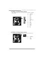
3.1 HOW TO SET UP JUMPERS
The illustration shows how to set up jumpers. When the jumper cap is
placed on pins, the jumper is “close”, if not, that means the jumper is
“open”.
Pin opened Pin closed Pin1-2 closed
3.2 DETAIL SET T ING S
JPANEL1: Front Panel Header
This 16-pin connector includes Power-on, Reset, HDD LED, Power LED, Sleep
button and speaker connection. It allows user to connect the PC case’s front
panel switch functions.
1
9
8
16
SLP
PW R
_
LED
On/Off
RST
HLED
SPK
++
+
-
-
Pin Assignment Function Pin Assignment Function
1 +5V 9 Sleep control
2 N/A 10 Ground
Sleep button
3 N/A 11 N/A N/A
4 Speaker
Speaker
Connector
12 Power LED (+)
5 HDD LED (+) 13 Power LED (+)
6 HDD LED (-)
Hard drive
LED
14 Power LED (-)
Power LED
7 Ground 15 Power button
8 Reset control
Reset button
16 Ground
Power-on button

865G Micro 775 & 865GV Micro 775
15
JATXPWR1: ATX Power Source Conne ctor
This connector allows user to connect 20-pin power connector on the ATX
power supply.
Pin Assignment
1 +3.3V
2 +3.3V
3 Ground
4 +5V
5 Ground
6 +5V
7 Ground
8 PW_OK
9 Standby Voltage
+5V
10 +12V
11 +3.3V
12 -12V
13 Ground
14 PS_ON
15 Ground
16 Ground
17 Ground
18 -5V
19 +5V
1
10
11
20
20 +5V
JATXPWR2: ATX Power Source Conne ctor
By connecting this connector, it will provide +12V to CPU power circuit.
Pin
Assignment
1 +12V
2 +12V
3 Ground
13
24
4 Ground

Motherboard Manual
16
JUSB2/JUSB3: Headers for USB 2.0 Ports at Front Panel
This header allows user to connect additional USB cable on the PC front panel,
and also can be connected with internal USB devices, like USB card reader.
Pin
Assignment
1 +5V (fused)
2 +5V (fused)
3 USB-
4 USB-
5 USB+
6 USB+
7 Ground
8 Ground
9 Key
1
2
9
10
JUSB2 JUSB3
10 NC
JUSBV2/JUSBV3_4: Power Source Headers for USB Ports
(Optional for 865G Micro 775)
Pin 1-2 Close:
JUSBV2/JUSBV3_4: +5V for USB ports at front panel (JUSB2/JUSB3).
Pin 2-3 Close:
JUSBV2/JUSBV3_4: USB ports at front panel (JUSB2/JUSB3) are powered
by +5V standby voltage.
31
1
3
Pin 1-2 close
JUSBV2
13
JUSBV3_4
13
3
1
1
3
Pin 2-3 close
Note:
In order to support this function “Power-On system via USB device,
“JUSBV2/JUSBV3_4” jumper cap should be placed on Pin 2-3 individually.

865G Micro 775 & 865GV Micro 775
17
JAUDIO2: Front Panel Audio Header
This header allows user to connect the front audio output cable with the PC front
panel. It will disable the output on back panel audio connectors.
Pin Assignment
1 Mic in/center
2 Ground
3 Mic power/Bass
4 Audio power
5 Right line out/
Speaker out
Right
6 Right line out/
Speaker out
Right
7 Reserved
8 Key
9 Left line out/
Speaker out Left
10 Left line out/
Speaker out Left
11 Right line in/
Rear speaker
Right
12 Right line in/
Rear speaker
Right
13 Left line in/
Rear speaker Left
1
2
13
14
14 Left line in/
Rear speaker Left
JCDIN1: CD-ROM Audio-in Connector
This connector allows user to connect the audio source from the variaty devices,
like CD-ROM, DVD-ROM, PCI sound card, PCI TV turner card etc..
Pin
Assignment
1 Left Channel
Input
2 Ground
3 Ground
14
4 Right Channel
Input

Motherboard Manual
18
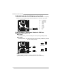
JCMOS1: Clear CMOS Header
By placing the jumper on pin2-3, it allows user to restore the BIOS safe setting
and the CMOS data, please carefully follow the procedures to avoid damaging
the motherboard.
1
3
Pin 1-2 Close:
Normal Operation (default).
13
1
3
Pin 2-3 Close:
Clear CMOS data.
※ Clear CMOS Procedures:
1. Remove AC power line.
2. Set the jumper to “Pin 2-3 close”.
3. Wait for five seconds.
4. Set the jumper to “Pin 1-2 close”.
5. Power on the AC.
6. Reset your desired password or clear the CMOS data.
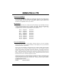
JSATA1~JSATA2: Serial ATA Connectors
The motherboard has a PCI to SATA Controller with 2 channels SATA interface,
it satisfies the SATA 1.0 spec and with transfer rate of 1.5Gb/s.
Pin
Assignment
1 Ground
2 TX+
3 TX-
4 Ground
5 RX-
6 RX+
SATA2
SATA1
147
7 Ground
Page is loading ...
Page is loading ...
Page is loading ...
Page is loading ...
Page is loading ...
Page is loading ...
Page is loading ...
Page is loading ...
Page is loading ...
Page is loading ...
Page is loading ...
Page is loading ...
Page is loading ...
Page is loading ...
Page is loading ...
Page is loading ...
Page is loading ...
Page is loading ...
Page is loading ...
Page is loading ...
Page is loading ...
Page is loading ...
Page is loading ...
Page is loading ...
Page is loading ...
Page is loading ...
Page is loading ...
Page is loading ...
Page is loading ...
Page is loading ...
Page is loading ...
Page is loading ...
Page is loading ...
Page is loading ...
Page is loading ...
Page is loading ...
Page is loading ...
Page is loading ...
Page is loading ...
Page is loading ...
Page is loading ...
Page is loading ...
Page is loading ...
Page is loading ...
Page is loading ...
Page is loading ...
Page is loading ...
Page is loading ...
Page is loading ...
Page is loading ...
Page is loading ...
Page is loading ...
Page is loading ...
Page is loading ...
Page is loading ...
Page is loading ...
Page is loading ...
Page is loading ...
Page is loading ...
Page is loading ...
Page is loading ...
Page is loading ...
Page is loading ...
Page is loading ...
Page is loading ...
-
 1
1
-
 2
2
-
 3
3
-
 4
4
-
 5
5
-
 6
6
-
 7
7
-
 8
8
-
 9
9
-
 10
10
-
 11
11
-
 12
12
-
 13
13
-
 14
14
-
 15
15
-
 16
16
-
 17
17
-
 18
18
-
 19
19
-
 20
20
-
 21
21
-
 22
22
-
 23
23
-
 24
24
-
 25
25
-
 26
26
-
 27
27
-
 28
28
-
 29
29
-
 30
30
-
 31
31
-
 32
32
-
 33
33
-
 34
34
-
 35
35
-
 36
36
-
 37
37
-
 38
38
-
 39
39
-
 40
40
-
 41
41
-
 42
42
-
 43
43
-
 44
44
-
 45
45
-
 46
46
-
 47
47
-
 48
48
-
 49
49
-
 50
50
-
 51
51
-
 52
52
-
 53
53
-
 54
54
-
 55
55
-
 56
56
-
 57
57
-
 58
58
-
 59
59
-
 60
60
-
 61
61
-
 62
62
-
 63
63
-
 64
64
-
 65
65
-
 66
66
-
 67
67
-
 68
68
-
 69
69
-
 70
70
-
 71
71
-
 72
72
-
 73
73
-
 74
74
-
 75
75
-
 76
76
-
 77
77
-
 78
78
-
 79
79
-
 80
80
-
 81
81
-
 82
82
-
 83
83
-
 84
84
-
 85
85


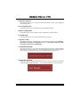
Ask a question and I''ll find the answer in the document
Finding information in a document is now easier with AI
Related papers
-
Biostar 865G Owner's manual
-
-
-
-
-
-
-
-
Biostar I86PE-A7 Owner's manual
-
Other documents
-
Asus P5K/EPU Owner's manual
-
Dell 56193617 Datasheet
-
Gigabyte GA-8IG1000MF Series User manual
-
Mach P4MST-890 Setup Manual
-
 IWILL FB24624100 User manual
-
Intel D865GRH User manual
-
Supermicro P4SPE User manual
-
-
Viglen VIG556M User manual
-
Sapling 50 Watt Power Supply Installation guide
